1 / 4
AirCFS-100NB
02-46/2019 Rev.: 0
2
5
Click!
3b1
+
-
4
10
1
4
5
6
5
3
9
7
8
11
+
-
2
Characteristics
Description
EN
General instrucions
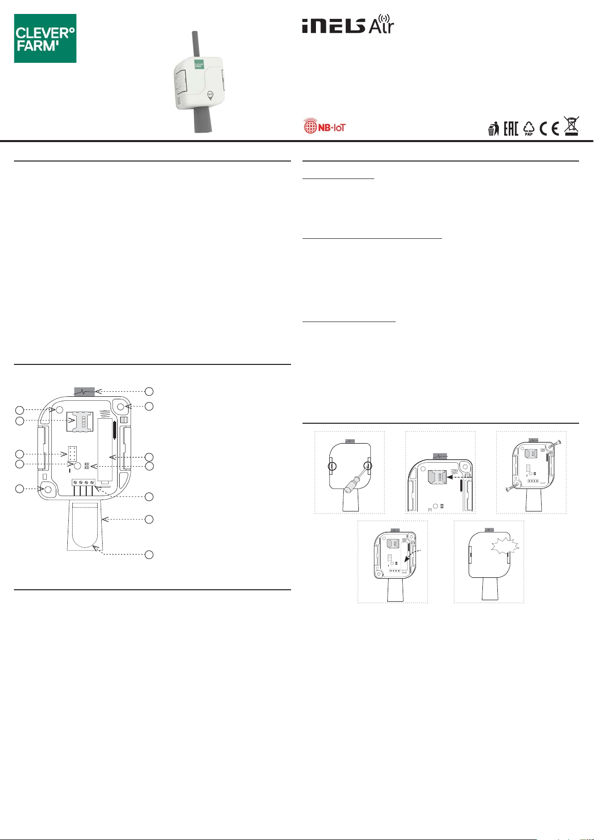
1. Tamper
2. NanoSIM slot
3. Programming pins
4. Button SET
5. Hole for mounting on the wall
Ø 4.3 mm / 0.2”
6. Antenna
7. Battery
8. LED indication
9. Sensor connection terminal
10. Sensor cover
11. S en so r
Cloud app assignment
It is done in your Smartphone application. Enter the relevant information on the product
cover into the application.
Set the sensing type (sensor LS, WS, MS or pulse output S0).
Temperature, humidity,
atmospheric pressure sensor
Made in Czech Republic
Assembly
1. Using a at-blade screwdriver gradually slide it into one groove and the other in the lid
and swing open the cover.
2. Carefully insert nanoSIM (the device must not be energized when inserting or replacing
nanoSIM!)
3. The product can be attached in two ways:
a) Directly on a at surface by gluing * - apply a suitable adhesive to the bottom of the
base. Place the base in the desired location and let it dry.
b) Using a suitable fastener ** by screwing - drill holes into the base with two holes of
suitable diameter corresponding to the position of the holes in the bottom of the box.
Place the base at the desired location and attach it with suitable bonding material
according to the substrate.
4. Insert the battery into the sensor and check correct location (the sensor functionality
message is sent to the application when the battery are inserted).
5. Replace and snap the front cover. When closing, the handles have to be snapped to their
original position. To ensure the degree of protection, tighten the grommet carefully.
* The glue must meet the optimal conditions for product placement (inuence of tem-
perature, humidity ...)
** For example, a screw or screw of max. Ø 4 mm can be used as a suitable fastener mate-
rial, 13 mm (distance to the partition in the box) must be added to the required length
for attachment to the substrate.
Internet of Things (IoT)
• The IOT wireless communications category describes the Low Power Wide Area
(LPWA). This technology is designed to provide full-range coverage both inside and
outside buildings, energy-saving and low-cost operation of individual devices. The
NarrowBand network is available to use this standard.
Information about the NarrowBand network
• The network provides two-way communication and the only one to use the licensed
LTE band. Our devices allow band 1 (2100MHz), Band 3 (1800MHz), Band 8 (900MHz),
Band 5 (850MHz), Band 20 (800MHz) and Band 28 (700MHz).
• It uses this SIM card technology for each device.
• The advantage of NarrowBand is the use of already built-up grids, which ensures suf-
cient reception outside and inside buildings.
• For more information on this technology, please visit www.vodafone.cz
Caution for proper operation:
• Products are installed according to the wiring diagram given for each product.
• For proper device functionality, it is necessary to have sucient coverage of the se-
lected network at the installation site.
• At the same time, the device must be registered in the network. Successful device reg-
istration on a given network requires a charge for trac.
• Each network oers dierent tari options - it always depends on the number of mes-
sages you want to send from your device. Information on these taris can be found in
the current version of the ELKO EP pricelist.
• The AirCFS-100 is designed to measure temperature, relative humidity and atmo-
spheric pressure.
• The device incorporates the IP65 design, so it is possible to use it in agriculture in
outdoor areas (down sensor), e.g. vineyards, orchards ...
• It is also suitable for use in harsh indoor areas, which require greater protection of
the device, for example. Greenhouses.
• With the wireless solution and NB-IoT communication, it can communicate instant-
ly to your chosen location and be operated immediately.
• Data is sent to the server from which it can be subsequently displayed as a smart-
phone, application, or Cloud notication
• Anti-sabotage: If access to the device is unauthorized, a message is immediately
sent to the server.
• Power supply 1x 3.6 V batteries SAFT.
• Battery power can be sent to the server when it is powered by a battery.
CleverFarm a.s.
Vídeňská 188/119d
619 00 Brno
www.cleverfarm.org


