EINHELL TC-PT 2500 User manual

TC-PT 2500
Art.-Nr.: 20.225.30 I.-Nr.: 11016
7
DOriginalbetriebsanleitung
Palettenhubwagen
GB Original operating instructions
Pallet Lifting Truck
IIstruzioni per l’uso originali
Transpallet
SOriginal-bruksanvisning
Palldragare
FIN Alkuperäiskäyttöohje
Paletinsiirtovaunu
PManual de instruções original
Carro elevador de paletes
HR/ Originalne upute za uporabu
BIH Kolica za podizanje paleta
GR Πρωτότυπες Οδηγίες χρήσης
Aνυψωτικό για παλέτες
CZ Originální návod k obsluze
Paletový vozík
SK Originálny návod na obsluhu
Paletový vozík
HEredeti használati utasítás
Palettaemelőkocsi
SLO Originalna navodila za uporabo
Dvigalo za palete
Anl_TC_PT_2500_SPK7.indb 1Anl_TC_PT_2500_SPK7.indb 1 10.04.2019 15:00:5110.04.2019 15:00:51

- 2 -
1
2
3
2
6
7
3
M
3
1
B
B
E
5
4
F
C
M
H
L
K
Anl_TC_PT_2500_SPK7.indb 2Anl_TC_PT_2500_SPK7.indb 2 10.04.2019 15:00:5210.04.2019 15:00:52

- 3 -
4 5
6
3C
M
BEA
(1)
(2)
(3)
Anl_TC_PT_2500_SPK7.indb 3Anl_TC_PT_2500_SPK7.indb 3 10.04.2019 15:00:5310.04.2019 15:00:53

D
- 4 -
Gefahr!
Beim Benutzen von Geräten müssen einige Si-
cherheitsvorkehrungen eingehalten werden, um
Verletzungen und Schäden zu verhindern. Lesen
Sie diese Bedienungsanleitung / Sicherheitshin-
weise deshalb sorgfältig durch. Bewahren Sie die-
se gut auf, damit Ihnen die Informationen jederzeit
zur Verfügung stehen. Falls Sie das Gerät an an-
dere Personen übergeben sollten, händigen Sie
diese Bedienungsanleitung / Sicherheitshinweise
bitte mit aus.Wir übernehmen keine Haftung für
Unfälle oder Schäden, die durch Nichtbeachten
dieser Anleitung und den Sicherheitshinweisen
entstehen.
1. Sicherheitshinweise
Gefahr!
Lesen Sie alle Sicherheitshinweise und An-
weisungen. Versäumnisse bei der Einhaltung der
Sicherheitshinweise und Anweisungen können
elektrischen Schlag, Brand und/oder schwere
Verletzungen verursachen. Bewahren Sie alle
Sicherheitshinweise und Anweisungen für
die Zukunft auf.
• Beachten Sie die geltenden Unfallverhü-
tungsvorschriften.
• Überschreiten Sie die angegeben Nutzlast
nicht.
• Verwenden Sie den Palettenhubwagen erst,
wenn Sie mit der Funktionsweise vertraut
sind, dazu ausgebildet und angewiesen wur-
den.
• Überprüfen Sie vor jeder Verwendung, das
Gerät auf Beschädigungen und Funktion.
• Verwenden Sie den Palettenhubwagen nicht
auf unebenen oder abschüssigen Unter-
grund.
• Der Palettenhubwagen besitzt serienmäßig
keine Bremse. Er darf nicht auf Steigungen
und Gefällen eingesetzt werden.
• Tragen Sie Arbeitshandschuhe und Sicher-
heitsschuhe.
• Der Aufenthalt unter angehobener Last ist
untersagt.
• Die zu transportierende Last ist gleichmäßig
auf den Hubgabeln zu verteilen.
• Transportieren Sie nie lose aufgestapelte
oder instabile Ladung.
• Der Palettenhubwagen darf nicht bei angeho-
benen Hubgabeln beladen werden.
• Lassen Sie niemals Lasten bei angehobenen
Hubgabeln unbeaufsichtigt.
• Greifen Sie niemals in bewegliche Teile.
• Keine Personen transportieren.
• Halten Sie beim Transport von Lasten einen
Mindestabstand von 60 cm zu anderen Per-
sonen.
• Der Arbeitsbereich muss gut ausgeleuchtet
sein.
2. Gerätebeschreibung und
Lieferumfang
2.1 Gerätebeschreibung (Bild 1)
1 Handgriff
2 Betätigungshebel
3 Zugdeichsel
4 Hydraulikeinheit
5 Lenkrollen
6 Hubgabeln
7 Lastrollen (Tandem)
2.2 Lieferumfang
• Öffnen Sie die Verpackung und nehmen Sie
das Gerät vorsichtig aus der Verpackung.
• Entfernen Sie das Verpackungsmaterial so-
wie Verpackungs-/ und Transportsicherungen
(falls vorhanden).
• Überprüfen Sie, ob der Lieferumfang vollstän-
dig ist.
• Kontrollieren Sie das Gerät und die Zubehör-
teile auf Transportschäden.
• Bewahren Sie die Verpackung nach Möglich-
keit bis zum Ablauf der Garantiezeit auf.
Gefahr!
Gerät und Verpackungsmaterial sind kein
Kinderspielzeug! Kinder dürfen nicht mit
Kunststoffbeuteln, Folien und Kleinteilen
spielen! Es besteht Verschluckungs- und Er-
stickungsgefahr!
• Palettenhubwagen
• Zugdeichsel
• Spannhülse
• Bolzen
• Originalbetriebsanleitung
Anl_TC_PT_2500_SPK7.indb 4Anl_TC_PT_2500_SPK7.indb 4 10.04.2019 15:00:5410.04.2019 15:00:54

D
- 5 -
3. Bestimmungsgemäße
Verwendung
Das Gerät ist nur zum Transport von Gütern auf
Paletten mit offener Bodenauflage oder mit
Querbrettern außerhalb der Lasträder auf festen,
ebenem Boden bestimmt. Es dürfen keine Perso-
nen mitgenommen oder gehoben werden.
Umgebungstemperatur von -20°C bis + 40°C.
Das Gerät darf nur nach ihrer Bestimmung ver-
wendet werden. Jede weitere darüber hinausge-
hende Verwendung ist nicht bestimmungsgemäß.
Für daraus hervorgerufene Schäden oder Verlet-
zungen aller Art haftet der Benutzer/Bediener und
nicht der Hersteller.
4. Technische Daten
Gesamthöhe:........................................ 1210 mm
Gesamtlänge: ....................................... 1500 mm
Gabellänge: .......................................... 1150 mm
Gabelhöhe min.:........................................ 80 mm
Gabelhöhe max.:..................................... 190 mm
Gabelbreite einzeln:................................ 153 mm
Gabelbreite gesamt: ............................... 540 mm
Hub max.: ............................................... 110 mm
Traglast: ..................................................2500 kg
Gewicht ca.:.................................................62 kg
Lenkräder Ø:........................................... 180 mm
Lastrollen Ø:.............................................. 80 mm
5. Montage
Hinweis: Die Hydraulik ist mit einem Bolzen (M)
gesichert. Entfernen Sie diesen erst, wenn Sie in
der nachfolgenden Montagebeschreibung dazu
aufgefordert werden und verwahren Sie ihn für
spätere Wartungsarbeiten.
1. (Abb. 1) Drücken Sie den Betätigungshebel
(2) ganz nach unten in Hebestellung (s. 6.
Betrieb).
2. (Abb. 2) Führen Sie die Steuerkette (F) durch
die Aussparung am unteren Deichselende
nach außen.
3. (Abb. 3) Stecken Sie den Bolzen (B) durch
das Loch der Deichselaufnahme (C) und der
Zugdeichsel. Achten Sie darauf, dass die
Spannhülsenführung (E) mit dem Spannhül-
senloch im Bolzen (B) übereinstimmt.
4. (Abb. 2) Führen Sie die Steuerkette (F) durch
das Loch im Bolzen (B) damit die Hydraulik
funktioniert.
5. (Abb. 3) Hängen Sie die Einstellschraube (H)
mit der vormontierten Sechskantmutter (K) in
den Hydraulikhebel (L) ein.
6. (Abb. 3) Drücken Sie die Deichsel (3) etwas
nach unten, der Hydrauliksicherungsbolzen
(M) wird dadurch gelockert und kann entnom-
men werden.
7. (Abb. 4) Prüfen Sie, ob die Spannhülsenauf-
nahme des Bolzens (B) mit der Spannhülsen-
führung (E) in der Deichselaufnahme überein-
stimmt. Schlagen Sie mit einem Hammer und
mit Hilfe des Hydrauliksicherungsbolzens (M)
links und rechts die Spannhülsen (A) in den
Bolzen (B).
Hinweis: Es besteht die Möglichkeit, das Gerät
mit einer Fußfeststellbremse auszustatten. Bei
Bedarf wenden Sie sich an ihren Kundendienst.
Funktion der Fußfeststellbremse:
Drücken Sie die Bremse bis zum Anschlag nach
rechts – die Räder werden blockiert.
Drücken Sie die Bremse nach links – die Räder
werden wieder frei gegeben.
6. Betrieb
Achtung! Beachten Sie die Sicherheitshinweise
(Abschnitt 1.) und Abbildung 6.
Auf der Zugdeichsel befindet sich ein Aufkleber
mit den Schaltgriffstellungen (Abb. 5).
1 = Senken (Absenkstellung)
2 = Fahren (Fahrstellung)
3 = Heben (Hebestellung)
Der Palettenhubwagen darf nur mit abgesenkten
Hubgabeln abgestellt werden.
Die folgenden Funktionen sind möglich und be-
reits vom Werk voreingestellt.
6.1 Anheben der Last (Abb. 1)
Drücken Sie den Betätigungshebel (2) nach
unten (Hebestellung). Anschließend bewegen
Sie die Zugdeichsel (3) mehrmals auf und ab. Da-
durch wird die Last angehoben.
Anl_TC_PT_2500_SPK7.indb 5Anl_TC_PT_2500_SPK7.indb 5 10.04.2019 15:00:5410.04.2019 15:00:54

D
- 6 -
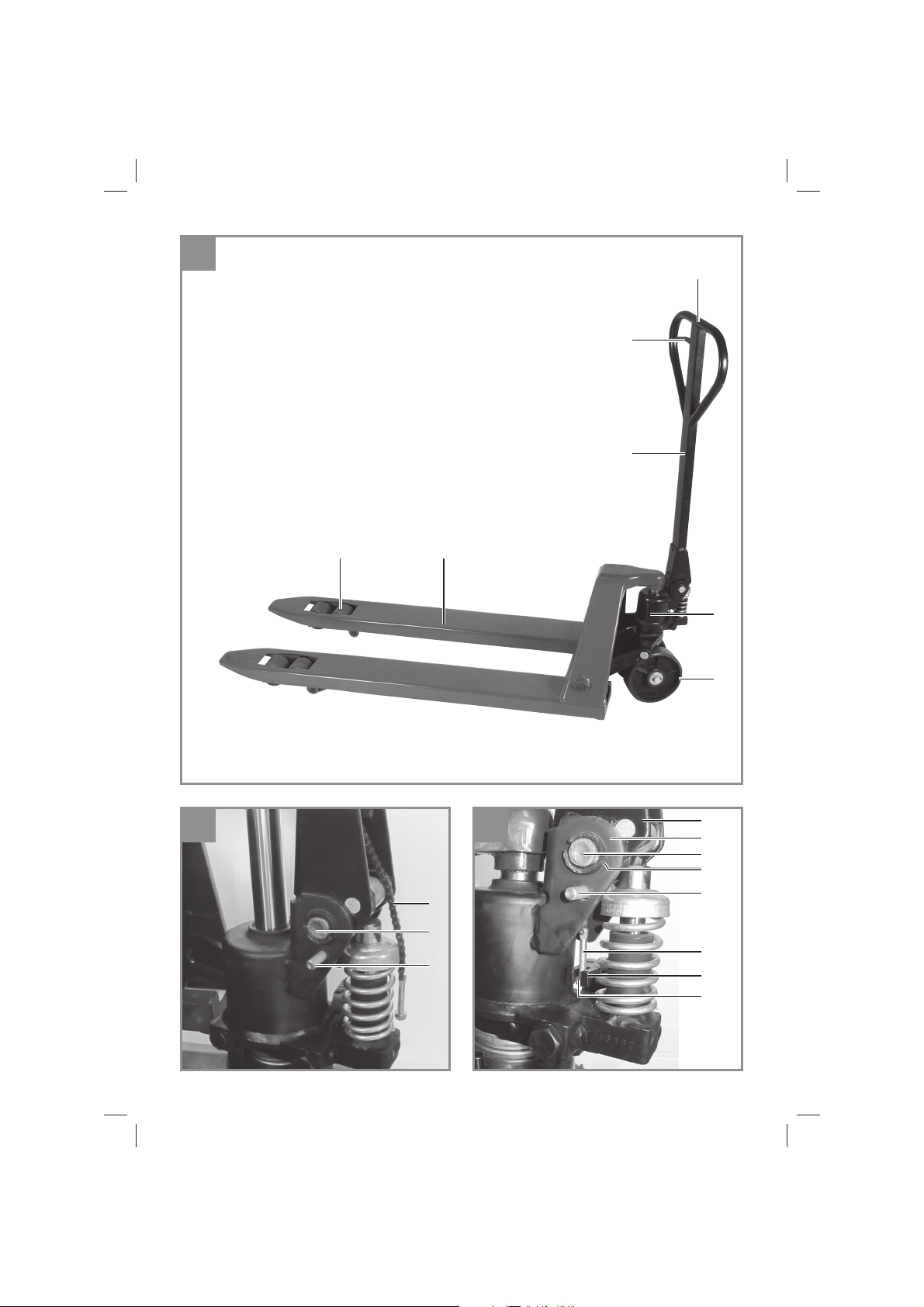
6.2 Ziehen der Last (Abb. 1)
Ziehen Sie den Betätigungshebel (2) in die mittle-
re Position (Fahrstellung). Die Hydraulik lässt sich
in dieser Position weder nach oben pumpen noch
absenken.
6.3 Absenken der Last (Abb. 1)
Bewegen Sie den Palettenhubwagen nicht und
ziehen Sie den Betätigungshebel (2) ganz nach
oben (Absenkstellung). Dadurch wird die Last
abgesenkt. Nach loslassen des Betätigungshe-
bels (2) bewegt er sich automatisch in die mittlere
Position (Fahrstellung) zurück.
7. Einstellung der
Hydrauliksteuerung
Falls die oben in Abschnitt 6. beschriebenen
Funktionen fehlerhaft arbeiten, wurde die Hydrau-
liksteuerung verändert und muss neu eingestellt
werden.
7.1 Hubgabeln heben sich in der Fahrstellung
(Abb. 3) Drehen Sie die Sechskantmutter (K) an
der Einstellschraube (H) solange im Uhrzeiger-
sinn, bis sich die Hubgabeln nicht mehr heben
und die Fahrstellung ordnungsgemäß funktioniert.
7.2 Hubgabeln senken sich in der Fahrstel-
lung
(Abb. 3) Drehen Sie die Sechskantmutter (K) an
der Einstellschraube (H) solange entgegen dem
Uhrzeigersinn, bis sich die Hubgabeln nicht mehr
senken und die Fahrstellung ordnungsgemäß
funktioniert.
7.3 Hubgabeln senken sich nicht in der Ab-
senkstellung
(Abb. 3) Drehen Sie die Sechskantmutter (K) an
der Einstellschraube (H) solange im Uhrzeiger-
sinn, bis sich die Hubgabeln durch hochziehen
des Betätigungshebels absenken. Prüfen Sie
anschließen die Funktion der Fahrstellung um zu
gewährleisten, dass sich die Einstellmutter in der
richtigen Position befindet.
7.4 Hubgabeln heben sich nicht in der Hebe-
stellung
(Abb. 3) Drehen Sie die Sechskantmutter (K) an
der Einstellschraube (H) solange entgegen dem
Uhrzeigersinn, bis sich die Hubgabeln in der He-
bestellung des Betätigungshebels anheben. Prü-
fen Sie anschließen die Funktion der Fahrstellung
und Absenkstellung um zu gewährleisten, dass
sich die Einstellmutter in der richtigen Position
befindet.
8. Reinigung, Wartung und
Ersatzteilbestellung
8.1 Reinigung
Zur Reinigung des Gehäuses ein leicht feuchtes
Tuch verwenden.
8.2 Wartung
Zur Erhaltung der Funktionsfähigkeit ist der Palet-
tenhubwagen regelmäßig zu überprüfen und ge-
gebenenfalls zu warten. Alle hier nicht aufgeführ-
ten Reparatur- und Wartungsarbeiten sind durch
einen Kundendienst oder einen autorisierten
Fachmann durchzuführen. Dies gilt im Besonde-
ren für das Wechseln von Lenk- und Lastrollen.
Bei Funktionsstörungen ist der Palettenhubwagen
unverzüglich außer Betrieb zu setzen und von ei-
ner autorisierten Person zu reparieren. Es dürfen
nur Original-Ersatzteile verwendet werden.
Mindestens jährlich, bei Bedarf auch öfter, ist der
Palettenhubwagen durch einen Sachkundigen
zu prüfen. Es wird empfohlen, die Prüfungen in
einem Prüfbuch festzuhalten.
Nach Reparatur oder Wartung vergewissern, ob
alle sicherheitstechnischen Teile angebracht und
in einwandfreiem Zustand sind. Verletzungsge-
fährdende Teile von anderen Personen und Kin-
dern unzugänglich aufbewahren.
Achtung: Laut Produkthaftungsgesetz haften
wir nicht für Schäden die durch unsachgemäße
Reparatur verursacht werden oder wenn bei Er-
satzteilen nicht Originalteile oder von uns freige-
gebene Teile verwendet werden. Ebenso haften
wir nicht für Schäden von unsachgemäßen Repa-
raturen. Beauftragen sie einen Kundendienst oder
einen autorisierten Fachmann. Entsprechendes
gilt auch für Zubehörteile.
8.2.1 Hydrauliköl auffüllen
Überprüfen Sie halbjährlich den Hydraulikölstand.
Zum Nachfüllen oder wechseln des Hydrauliköls
verwenden Sie nur Hydrauliköl der Viskositäts-
klassen HLP 46 (- 20 °C - + 40°C) . Die Füllmen-
ge beträgt ca. 0,4 Liter.
Achtung! Zur Vermeidung von Umweltbelastun-
gen durch Ölaustritt bei der Wartung des Gerätes
Anl_TC_PT_2500_SPK7.indb 6Anl_TC_PT_2500_SPK7.indb 6 10.04.2019 15:00:5410.04.2019 15:00:54

D
- 7 -
ist austretendes Öl frühzeitig durch saugfähige
Materialien (z.B. Holzspäne, trockene Stofflap-
pen) zu binden.Verschmutztes Wartungsmaterial
und Betriebsstoffe in einer dafür vorgesehenen
Sammelstelle abgeben und das verschmutzte
Material ordnungsgemäß zu entsorgen.
1. Hubgabeln vollständig absenken
2. Öleinfüllschraube und Dichtung vom Ölbehäl-
ter entfernen.
3. Hydrauliköl bis zum Bohrungsrand einfüllen
4. Öleinfüllschraube und Dichtung wieder in den
Ölbehälter einschrauben.
5. Hydrauliksystem mit mehreren Pumpbewe-
gungen der Zugdeichsel entlüften
8.3 Hydraulikeinheit entlüften
Sollten sich die Hubgabeln in der Hebestellung
nicht heben, stellen Sie den Betätigungshebel auf
die Senkposition und bewegen Sie die Zugdeich-
sel mehrmals auf und ab.
8.4 Bewegliche Teile schmieren
Bewegliche Teile regelmäßig schmieren und
fetten.
8.5 Ersatzteilbestellung:
Bei der Ersatzteilbestellung sollten folgende An-
gaben gemacht werden;
• Typ des Gerätes
• Artikelnummer des Gerätes
• Ident-Nummer des Gerätes
• Ersatzteilnummer des erforderlichen Ersatz-
teils
Aktuelle Preise und Infos finden Sie unter
www.isc-gmbh.info
9. Entsorgung und
Wiederverwertung
Das Gerät befindet sich in einer Verpackung um
Transportschäden zu verhindern. Diese Verpa-
ckung ist Rohstoffund ist somit wieder verwend-
bar oder kann dem Rohstoffkreislauf zurückge-
führt werden. Das Gerät und dessen Zubehör
bestehen aus verschiedenen Materialien, wie
z.B. Metall und Kunststoffe. Defekte Geräte ge-
hören nicht in den Hausmüll. Zur fachgerechten
Entsorgung sollte das Gerät an einer geeigneten
Sammelstellen abgegeben werden.Wenn Ihnen
keine Sammelstelle bekannt ist, sollten Sie bei
der Gemeindeverwaltung nachfragen.
10. Lagerung
Wird der Palettenhubwagen längere Zeit nicht
benutzt, lagern Sie ihn gründlich gereinigt, ab-
geschmiert und abgedeckt an einem dunklen,
trockenen und frostfreiem sowie für Kinder unzu-
gänglichem Ort. Die optimale Lagertemperatur
liegt zwischen 5 und 30 ˚C.
Anl_TC_PT_2500_SPK7.indb 7Anl_TC_PT_2500_SPK7.indb 7 10.04.2019 15:00:5410.04.2019 15:00:54

D
- 8 -
11. Hinweise zur Fehlerbeseitigung
Wird das Gerät richtig betrieben, dürften keine Störungen auftreten. Bei Störungen prüfen Sie die fol-
genden Möglichkeiten, bevor Sie den Kundendienst verständigen.
Störung Mögliche Ursache Behebung
Hubgabeln lassen
sich nicht bis zur
Maximalhöhe an-
heben
- zu wenig Hydrauliköl - Hydrauliköl nachfüllen
Hubgabeln lassen
sich nicht anheben
- kein Hydrauliköl vorhanden
- Hydrauliköl verschmutzt
- Einstellmutter (K) ist zu hoch einge-
stellt
- Luft in Hydraulikeinheit
- Hydrauliköl einfüllen
- Hydrauliköl wechseln
- Einstellmutter (K) einstellen (s. Ka-
pitel 7.)
- Hydraulikeinheit entlüften (s. Kapitel
8.)
Hubgabeln lassen
sich nicht senken
- Kolbenstange oder Pumpenge-
häuse aufgrund Überladung oder
ungleichmäßiger Lastverteilung
beschädigt
- Kolben ist fest
- Einstellmutter (K) ist falsch einge-
stellt
- Kolbenstange bzw. Pumpengehäu-
se austauschen*
- Kolben austauschen*
- Einstellmutter (K) einstellen (s. Ka-
pitel 7.)
Undichte Stellen - Dichtungen sind verschlissen oder-
beschädigt
- Hydraulikbauteil defekt
- Dichtungen ersetzen*
- Hydraulikbauteil ersetzen*
Hubgabeln senken
sich, ohne dass das
Ablassventil funkti-
oniert
- Hydrauliköl verschmutzt
- Hydraulikbauteil defekt
- Luft in Hydraulikeinheit
- Dichtungen sind verschlissen oder
beschädigt
- Einstellmutter (K) ist falsch einge-
stellt
- Hydrauliköl wechseln
- Hydraulikbauteil ersetzen*
- Hydraulikeinheit entlüften (s. Kapitel
8.)
- Dichtungen ersetzen*
- Einstellmutter (K) einstellen (s. Ka-
pitel 7.)
Achtung!
* Diese Arbeiten müssen vom qualifizierten zugelassenen Fachpersonal ausgeführt werden.
Der Nachdruck oder sonstige Vervielfältigung von Dokumentation und Begleitpapieren der Produkte,
auch auszugsweise, ist nur mit ausdrücklicher Zustimmung der iSC GmbH zulässig.
Technische Änderungen vorbehalten
Anl_TC_PT_2500_SPK7.indb 8Anl_TC_PT_2500_SPK7.indb 8 10.04.2019 15:00:5410.04.2019 15:00:54

D
- 9 -
Garantieurkunde
Sehr geehrte Kundin, sehr geehrter Kunde,
unsere Produkte unterliegen einer strengen Qualitätskontrolle. Sollte dieses Gerät dennoch einmal nicht
einwandfrei funktionieren, bedauern wir dies sehr und bitten Sie, sich an unseren Servicedienst unter
der auf dieser Garantiekarte angegebenen Adresse zu wenden. Gerne stehen wir Ihnen auch telefo-
nisch über die angegebene Servicerufnummer zur Verfügung. Für die Geltendmachung von Garantiean-
sprüchen gilt folgendes:
1. Diese Garantiebedingungen richten sich ausschließlich an Verbraucher, d. h. natürliche Personen,
die dieses Produkt weder im Rahmen ihrer gewerblichen noch anderen selbständigen Tätigkeit
nutzen wollen. Diese Garantiebedingungen regeln zusätzliche Garantieleistungen, die der u. g.
Hersteller zusätzlich zur gesetzlichen Gewährleistung Käufern seiner Neugeräte verspricht. Ihre
gesetzlichen Gewährleistungsansprüche werden von dieser Garantie nicht berührt. Unsere Garan-
tieleistung ist für Sie kostenlos.
2. Die Garantieleistung erstreckt sich ausschließlich auf Mängel an einem von Ihnen erworbenen neu-
en Gerät des u. g. Herstellers, die auf einem Material- oder Herstellungsfehler beruhen und ist nach
unserer Wahl auf die Behebung solcher Mängel am Gerät oder den Austausch des Gerätes be-
schränkt. Bitte beachten Sie, dass unsere Geräte bestimmungsgemäß nicht für den gewerblichen,
handwerklichen oder beruflichen Einsatz konstruiert wurden. Ein Garantievertrag kommt daher nicht
zustande, wenn das Gerät innerhalb der Garantiezeit in Gewerbe-, Handwerks- oder Industriebe-
trieben verwendet wurde oder einer gleichzusetzenden Beanspruchung ausgesetzt war.
3. Von unserer Garantie ausgenommen sind:
- Schäden am Gerät, die durch Nichtbeachtung der Montageanleitung oder aufgrund nicht fach-
gerechter Installation, Nichtbeachtung der Gebrauchsanleitung (wie durch z.B. Anschluss an eine
falsche Netzspannung oder Stromart) oder Nichtbeachtung der Wartungs- und Sicherheitsbestim-
mungen oder durch Aussetzen des Geräts an anomale Umweltbedingungen oder durch mangelnde
Pflege und Wartung entstanden sind.
- Schäden am Gerät, die durch missbräuchliche oder unsachgemäße Anwendungen (wie z.B. Über-
lastung des Gerätes oder Verwendung von nicht zugelassenen Einsatzwerkzeugen oder Zubehör),
Eindringen von Fremdkörpern in das Gerät (wie z.B. Sand, Steine oder Staub, Transportschäden),
Gewaltanwendung oder Fremdeinwirkungen (wie z. B. Schäden durch Herunterfallen) entstanden
sind.
- Schäden am Gerät oder an Teilen des Geräts, die auf einen gebrauchsgemäßen, üblichen oder
sonstigen natürlichen Verschleiß zurückzuführen sind.
4. Die Garantiezeit beträgt 24 Monate und beginnt mit dem Kaufdatum des Gerätes. Garantieansprü-
che sind vor Ablauf der Garantiezeit innerhalb von zwei Wochen, nachdem Sie den Defekt erkannt
haben, geltend zu machen. Die Geltendmachung von Garantieansprüchen nach Ablauf der Ga-
rantiezeit ist ausgeschlossen. Die Reparatur oder der Austausch des Gerätes führt weder zu einer
Verlängerung der Garantiezeit noch wird eine neue Garantiezeit durch diese Leistung für das Gerät
oder für etwaige eingebaute Ersatzteile in Gang gesetzt. Dies gilt auch bei Einsatz eines Vor-Ort-
Services.
5. Für die Geltendmachung Ihres Garantieanspruches melden Sie bitte das defekte Gerät an unter:
www.isc-gmbh.info. Halten Sie bitte den Kaufbeleg oder andere Nachweise Ihres Kaufs des Neu-
geräts bereit. Geräte, die ohne entsprechende Nachweise oder ohne Typenschild eingesendet wer-
den, sind von der Garantieleistung aufgrund mangelnder Zuordnungsmöglichkeit ausgeschlossen.
Ist der Defekt des Gerätes von unserer Garantieleistung erfasst, erhalten Sie umgehend ein repa-
riertes oder neues Gerät zurück.
Selbstverständlich beheben wir gegen Erstattung der Kosten auch gerne Defekte am Gerät, die vom
Garantieumfang nicht oder nicht mehr erfasst sind. Dazu senden Sie das Gerät bitte an unsere Service-
adresse.
Für Verschleiß-, Verbrauchs- und Fehlteile verweisen wir auf die Einschränkungen dieser Garantie ge-
mäß den Service-Informationen dieser Bedienungsanleitung.
iSC GmbH · Eschenstraße 6 · 94405 Landau/Isar (Deutschland)
Anl_TC_PT_2500_SPK7.indb 9Anl_TC_PT_2500_SPK7.indb 9 10.04.2019 15:00:5510.04.2019 15:00:55

D
- 10 -
Sehr geehrte Kundin, sehr geehrter Kunde,
um Ihnen noch mehr Service zu bieten, haben Sie die Möglichkeit auf unserem Onlineportal weitere
Informationen abzurufen.
Sollten einmal Probleme oder Fragen zu Ihrem Produkt auftreten, können Sie schnell und einfach unter
www.isc-gmbh.info viele Aktionen durchführen. Hier einige Beispiele:
• Ersatzteile bestellen
• Aktuelle Preisauskünfte
• Verfügbarkeiten der Ersatzteile
• Servicestellen Vorort für Benzingeräte
• Defekte Geräte anmelden
• Garantieverlängerungen (nur bei bestimmten Geräten)
• Bestellverfolgung
Wir freuen uns auf Ihren Besuch online unter www.isc-gmbh.info!
Telefon: 09951 / 95 920 00 ·Telefax: 09951/95 917 00
iSC GmbH · Eschenstraße 6 · 94405 Landau/Isar (Deutschland)
Anl_TC_PT_2500_SPK7.indb 10Anl_TC_PT_2500_SPK7.indb 10 10.04.2019 15:00:5510.04.2019 15:00:55

GB
- 11 -
Danger!
When using the equipment, a few safety pre-
cautions must be observed to avoid injuries and
damage. Please read the complete operating
instructions and safety regulations with due care.
Keep this manual in a safe place, so that the in-
formation is available at all times. If you give the
equipment to any other person, hand over these
operating instructions and safety regulations as
well.We cannot accept any liability for damage
or accidents which arise due to a failure to follow
these instructions and the safety instructions.
1. Safety regulations
Danger!
Read all safety regulations and instructions.
Any errors made in following the safety regula-
tions and instructions may result in an electric
shock, fire and/or serious injury.
Keep all safety regulations and instructions
in a safe place for future use.
• Pay attention to the accident prevention re-
gulations.
• Never exceed the specified payload.
• Do not use the pallet lifting truck until you
have familiarized yourself with its mode of
operation and been trained and instructed on
how to use it.
• Check the equipment for damage and make
sure that it is in good working order each time
before you use it.
• Do not use the pallet lifting truck on uneven
ground or slopes.
• The pallet lifting truck has no brake. It is not
allowed to be used on upward or downward
inclines.
• Wear work gloves and safety shoes.
• It is imperative to stay clear of the area under
lifted loads.
• The load you want to transport must be distri-
buted evenly over the lifting forks.
• Never transport loosely piled loads or unsta-
ble loads.
• The pallet lifting truck is not allowed to be
loaded when the lifting forks are in a raised
position.
• Loads on raised lifting forks must never be left
unattended.
• Do not reach into moving parts.
• Do not transport people.
• Keep a minimum distance of 60 cm from
other persons when transporting loads.
• The work area must be well illuminated.
2. Layout and items supplied
2.1 Layout (Fig. 1)
1 Handle
2 Control lever
3 Drawbar
4 Hydraulic unit
5 Steering rollers
6 Lifting forks
7 Load-bearing rollers (tandem)
2.2 Items supplied
Please check that the article is complete as
specified in the scope of delivery. If parts are
missing, please contact our service center or the
sales outlet where you made your purchase at
the latest within 5 working days after purchasing
the product and upon presentation of a valid bill
of purchase. Also, refer to the warranty table in
the service information at the end of the operating
instructions.
• Open the packaging and take out the equip-
ment with care.
• Remove the packaging material and any
packaging and/or transportation braces (if
available).
• Check to see if all items are supplied.
• Inspect the equipment and accessories for
transport damage.
• If possible, please keep the packaging until
the end of the guarantee period.
Danger!
The equipment and packaging material are
not toys. Do not let children play with plastic
bags, foils or small parts. There is a danger of
swallowing or suffocating!
• Pallet lifting truck
• Drawbar
• Clamp sleeve
• Bolt
• Original operating instructions
Anl_TC_PT_2500_SPK7.indb 11Anl_TC_PT_2500_SPK7.indb 11 10.04.2019 15:00:5510.04.2019 15:00:55

GB
- 12 -
3. Proper use
The equipment is designed for transporting goods
on pallets with an open base or with stringer
boards extending beyond the load wheels.The
equipment must be used on a firm, flat surface.
It is prohibited to use the equipment to pick up or
transport people.
Ambient temperature of -20°C to +40°C.
The equipment is to be used only for its prescri-
bed purpose. Any other use is deemed to be a
case of misuse.The user / operator and not the
manufacturer will be liable for any damage or inju-
ries of any kind caused as a result of this.
4. Technical data
Overall height: ...................................... 1210 mm
Overall length: ...................................... 1500 mm
Fork length: .......................................... 1150 mm
Fork height min.: ....................................... 80 mm
Fork height max.: .................................... 190 mm
Fork width single: ................................... 153 mm
Fork width total: ...................................... 540 mm
Lift max.: ................................................ 110 mm
Load:........................................................2500 kg
Weight approx.: ...........................................62 kg
Steering wheels Ø: ................................. 180 mm
Load-bearing rollers Ø:............................. 80 mm
5. Assembly
Note: The hydraulic system is secured with a bolt
(M). Do not remove it until prompted in the fol-
lowing assembly description and keep it in a safe
place for future maintenance work.
1. (Fig. 1) Press down the control lever (2) as far
as it will go into the lowering position (see 6.
Functions).
2. (Fig. 2) Pass the control chain (F) through
and out of the recess at the bottom end of the
drawbar.
3. (Fig. 3) Insert the bolt (B) through the hole
in the drawbar mount (C) and the hole in the
drawbar. Make sure that the clamping sleeve
passage (E) coincides with the clamping
sleeve hole in the bolt (B).
4. (Fig. 2) Pass the control chain (F) through the
hole in the bolt (B) so that the hydraulics sys-
tem works.
5. (Fig. 3) Hook the setting screw (H) with the
pre-mounted hex nut (K) into the hydraulics
lever (L).
6. (Fig. 3) Press the drawbar (3) down a little so
that the hydraulics lock bolt (M) is slackened
and can be removed.
7. (Fig. 4) Check whether the clamping slee-
ve mount of the bolt (B) coincides with the
clamping sleeve passage (E) in the drawbar
mount. Use a hammer and the hydraulics lock
bolt (M) to hit the sleeves (A) into the bolt (B)
on the left and right.
Note: The equipment can be optionally equipped
with a foot-activated parking brake. If required,
please contact your customer service team.
Operating the foot-activated parking brake:
Push the brake to the right as far as the stop – the
wheels will be blocked.
Push the brake to the left – the wheels will be
released again.
6. Functions
Important! Note the safety information (section 1.)
and Figure 6.
On the drawbar is a sticker showing the positions
of the handle switch (Fig. 5).
1 = Lower (lowering position)
2 = Travel (traveling position)
3 = Lift (lifting position)
The pallet lifting truck is allowed to be parked only
when the lifting forks are lowered.
The following functions are possible and were
already set in the factory.
6.1 Lifting the load (Fig. 1)
Press down the control lever (2) (lifting position).
Then pump the drawbar (3) up and down several
times. The load will be lifted.
6.2 Pulling the load (Fig. 1)
Pull up the control lever (2) into the middle
position (traveling position). In this position the
hydraulics cannot be used for lifting or lowering.
Anl_TC_PT_2500_SPK7.indb 12Anl_TC_PT_2500_SPK7.indb 12 10.04.2019 15:00:5510.04.2019 15:00:55

GB
- 13 -
6.3 Lowering the load (Fig. 1)
With the pallet lifting truck at a standstill, pull up
the control lever (2) to the very top (lowering posi-
tion). The load will be lowered. When you now
release the control lever (2), it will automatically
return to the middle position (traveling position).
7. Setting the hydraulics control
system
The functions described in section 6. will not work
correctly if the hydraulics control settings are
altered. In this case you must re-set the hydrau-
lics control system.
7.1 The lifting forks rise when the control
lever is in the traveling position
(Fig. 3) Turn the hex nut (K) on the setting screw
(H) clockwise to the point where the lifting forks
no longer rise and the traveling position works
correctly.
7.2 The lifting forks descend when the control
lever is in the traveling position
(Fig. 3) Turn the hex nut (K) on the setting screw
(H) counter-clockwise to the point where the
lifting forks no longer descend and the traveling
position works correctly.
7.3 The lifting forks do not descend when the
control lever is in the lowering position
(Fig. 3) Turn the hex nut (K) on the setting screw
(H) clockwise to the point where the lifting forks
are lowered by pulling up the control lever. Then
check the operation of the traveling position in
order to guarantee that the setting nut is in the
correct position.
7.4 The lifting forks do not rise when the
control lever is in the lifting position
(Fig. 3) Turn the hex nut (K) on the setting screw
(H) counter-clockwise to the point where the
lifting forks are raised when the control lever is in
the lifting position. Then check the operation of
the traveling position and the lowering position
in order to guarantee that the setting nut is in the
correct position.
8. Cleaning, maintenance and orde-
ring of spare parts
8.1 Cleaning
Use a damp cloth to clean the casing.
8.2 Servicing
The pallet lifting truck must be regularly inspected
and if necessary serviced in order to keep it in
good working order. All the repair and mainte-
nance jobs which are not listed here must be
carried out by a customer service center or an
authorized specialist. This applies in particular to
replacing the steering and load-bearing rollers.
If malfunctions arise, the pallet lifting truck must
be taken out of operation immediately and be
repaired by an authorized person. Only original
spare parts are allowed to be used.
The pallet lifting truck must be inspected by an
expert at least once a year or more often if neces-
sary. It is recommended to record the inspections
in an inspection book.
After carrying out repair or maintenance work,
ensure that all safety parts are installed and in
perfect condition.
Store potentially hazardous parts out of the reach
of other persons and children.
Important: In accordance with the German
Product Liability Act, we are not liable for any
damages if they result from improper repairs
to the product or if parts are replaced by items
other than genuine parts or parts approved by us.
Furthermore, we are not liable for any damages if
they result from improper repairs to the product.
Arrange for your customer service or an autho-
rized workshop to do the work. The same applies
to accessory parts.
8.2.1 Filling up with hydraulic oil
Check the oil level every six months. When fill-
ing up with hydraulic oil or replacing it, use only
hydraulic oil from the viscosity classes HLP 46 (-
20 °C - + 40°C) . A complete filling equals approx.
0.4 liters.
Anl_TC_PT_2500_SPK7.indb 13Anl_TC_PT_2500_SPK7.indb 13 10.04.2019 15:00:5610.04.2019 15:00:56

GB
- 14 -
Important! To prevent environmental contami-
nation from escaping oil, use absorbent materials
(e.g. wood chips, dry rags) promptly to pick up
any oil spills. Take soiled maintenance material
and operating materials to an appropriate col-
lection point and dispose of the soiled material
correctly.
1. Lower the lifting forks as far as possible
2. Remove the oil filler plug and seal from the oil
tank.
3. Fill in hydraulic oil up to the brim
4. Reinsert the oil filler plug and seal into the oil
tank.
5. Vent the hydraulics system with several pum-
ping movements of the drawbar
8.3 Venting the hydraulic unit
If the lifting forks do not rise when the control
lever is in the lifting position, move the control
lever into the lower position and move the draw-
bar up and down again several times.
8.4 Lubricating the moving parts
Lubricate and grease the moving parts regularly.
8.5 Ordering replacement parts:
Please quote the following data when ordering
replacement parts:
• Type of machine
• Article number of the machine
• Identification number of the machine
• Replacement part number of the part required
For our latest prices and information please go to
www.isc-gmbh.info
9. Disposal and recycling
The equipment is supplied in packaging to pre-
vent it from being damaged in transit. The raw
materials in this packaging can be reused or
recycled.The equipment and its accessories are
made of various types of material, such as metal
and plastic. Never place defective equipment in
your household refuse.The equipment should
be taken to a suitable collection center for proper
disposal. If you do not know the whereabouts of
such a collection point, you should ask in your
local council offices.
10. Storage
Store the equipment and accessories in a dark
and dry place at above freezing temperature.The
ideal storage temperature is between 5 and 30
°C. Store the electric tool in its original packaging.
Anl_TC_PT_2500_SPK7.indb 14Anl_TC_PT_2500_SPK7.indb 14 10.04.2019 15:00:5610.04.2019 15:00:56

GB
- 15 -
11. Troubleshooting
If the equipment is operated properly you should experience no problems with malfunctions or faults.
In the event of any malfunctions or faults, please check the following before you contact your customer
services.
Fault Possible cause Remedy
The lifting forks
cannot be raised to
the maximum height
Too little hydraulic oil Fill in hydraulic oil
The lifting forks
cannot be raised
No hydraulic oil
The hydraulic oil is dirty
The setting nut (K) is too high
Air in the hydraulic unit
Fill in hydraulic oil
Change the hydraulic oil
Set the setting nut (K) (see section 7.)
Vent the hydraulic unit (see section 8.)
The lifting forks
cannot be lowered
The piston rod or pump housing has
been damaged by overloading or an
uneven load distribution
The piston is stuck
The setting nut (K) is set wrongly
Replace the piston rod or pump
housing*
Replace the piston*
Set the setting nut (K) (see section 7.)
Leaks The seals are worn or damaged
The hydraulic module is defective
Replace the seals*
Replace the hydraulic module*
The lifting forks
descend without the
relief valve working
The hydraulic oil is dirty
The hydraulic module is defective
Air in the hydraulic unit
The seals are worn or damaged
The setting nut (K) is set wrongly
Change the hydraulic oil
Replace the hydraulic module*
Vent the hydraulic unit (see section 8.)
Replace the seals*
Set the setting nut (K) (see section 7.)
Important!
* This work must be performed by qualified and approved specialists.
The reprinting or reproduction by any other means, in whole or in part, of documentation and papers
accompanying products is permitted only with the express consent of the iSC GmbH.
Subject to technical changes
Anl_TC_PT_2500_SPK7.indb 15Anl_TC_PT_2500_SPK7.indb 15 10.04.2019 15:00:5610.04.2019 15:00:56

GB
- 16 -
Warranty certificate
Dear Customer,
All of our products undergo strict quality checks to ensure that they reach you in perfect condition. In the
unlikely event that your device develops a fault, please contact our service department at the address
shown on this guarantee card.You can also contact us by telephone using the service number shown.
Please note the following terms under which guarantee claims can be made:
1. These guarantee terms apply to consumers only, i.e. natural persons intending to use this product
neither for their commercial activities nor for any other self-employed activities. These warranty
terms regulate additional warranty services, which the manufacturer mentioned below promises to
buyers of its new products in addition to their statutory rights of guarantee.Your statutory guarantee
claims are not affected by this guarantee. Our guarantee is free of charge to you.
2. The warranty services cover only defects due to material or manufacturing faults on a product which
you have bought from the manufacturer mentioned below and are limited to either the rectification of
said defects on the product or the replacement of the product, whichever we prefer.
Please note that our devices are not designed for use in commercial, trade or professional applica-
tions. A guarantee contract will not be created if the device has been used by commercial, trade or
industrial business or has been exposed to similar stresses during the guarantee period.
3. The following are not covered by our guarantee:
- Damage to the device caused by a failure to follow the assembly instructions or due to incorrect
installation, a failure to follow the operating instructions (for example connecting it to an incorrect
mains voltage or current type) or a failure to follow the maintenance and safety instructions or by ex-
posing the device to abnormal environmental conditions or by lack of care and maintenance.
- Damage to the device caused by abuse or incorrect use (for example overloading the device or the
use or unapproved tools or accessories), ingress of foreign bodies into the device (such as sand,
stones or dust, transport damage), the use of force or damage caused by external forces (for ex-
ample by dropping it).
- Damage to the device or parts of the device caused by normal or natural wear or tear or by normal
use of the device.
4. The guarantee is valid for a period of 24 months starting from the purchase date of the device. Gu-
arantee claims should be submitted before the end of the guarantee period within two weeks of the
defect being noticed. No guarantee claims will be accepted after the end of the guarantee period.
The original guarantee period remains applicable to the device even if repairs are carried out or
parts are replaced. In such cases, the work performed or parts fitted will not result in an extension
of the guarantee period, and no new guarantee will become active for the work performed or parts
fitted.This also applies if an on-site service is used.
5. To make a claim under the guarantee, please register the defective device at: www.isc-gmbh.info.
Please keep your bill of purchase or other proof of purchase for the new device. Devices that are
returned without proof of purchase or without a rating plate shall not be covered by the guarantee,
because appropriate identification will not be possible. If the defect is covered by our guarantee,
then the item in question will either be repaired immediately and returned to you or we will send you
a new replacement.
Of course, we are also happy offer a chargeable repair service for any defects which are not covered by
the scope of this guarantee or for units which are no longer covered.To take advantage of this service,
please send the device to our service address.
Also refer to the restrictions of this warranty concerning wear parts, consumables and missing parts as
set out in the service information in these operating instructions.
Anl_TC_PT_2500_SPK7.indb 16Anl_TC_PT_2500_SPK7.indb 16 10.04.2019 15:00:5610.04.2019 15:00:56

I
- 17 -
Pericolo!
Nell’usare gli apparecchi si devono rispettare
diverse avvertenze di sicurezza per evitare lesi-
oni e danni. Quindi leggete attentamente queste
istruzioni per l’uso/le avvertenze di sicurezza.
Conservate bene le informazioni per averle a
disposizione in qualsiasi momento. Se date
l’apparecchio ad altre persone, consegnate ques-
te istruzioni per l’uso/le avvertenze di sicurezza
insieme all’apparecchio. Non ci assumiamo al-
cuna responsabilità per incidenti o danni causati
dal mancato rispetto di queste istruzioni e delle
avvertenze di sicurezza.
1. Avvertenze sulla sicurezza
Pericolo!
Leggete tutte le avvertenze di sicurezza e le
istruzioni. Dimenticanze nel rispetto delle avver-
tenze di sicurezza e delle istruzioni possono cau-
sare scosse elettriche, incendi e/o gravi lesioni.
Conservate tutte le avvertenze e le istruzioni
per eventuali necessità future.
• Rispettate le norme infortunistiche vigenti.
• Non superate il carico utile indicato.
• Utilizzate il transpallet solo dopo aver acquisi-
to familiarità con il funzionamento ed essere
stati istruiti e informati al riguardo.
• Controllate prima di ogni utilizzo che
l’apparecchio non sia danneggiato e funzioni
correttamente.
• Non utilizzate il transpallet su superfici irrego-
lari o ripide.
• Il transpallet non è dotato di serie di freni. Non
deve essere utilizzato in pendenza o su piani
molto inclinati.
• Indossate guanti da lavoro e scarpe di sicu-
rezza.
• È vietato sostare sotto i carichi sospesi.
• Il carico da trasportare deve essere distribuito
uniformemente sulle forche.
• Non devono essere mai trasportati carichi
instabili o che non siano ben impilati.
• Il transpallet non deve essere caricato con le
forche sollevate.
• Non lasciate mai carichi senza sorveglianza
quando le forche sono sollevate.
• Non mettete mai le mani nelle parti mobili.
• Non trasportate persone.
• Mantenete una distanza minima di 60 cm da
altre persone durante il trasporto di carichi.
• La zona di lavoro deve essere ben illuminata.
2. Descrizione dell’apparecchio ed
elementi forniti
2.1 Descrizione dell’apparecchio (Fig. 1)
1 Impugnatura
2 Leva di azionamento
3 Timone
4 Unità idraulica
5 Rotelle orientabili
6 Forche
7 Ruote di carico (tandem)
2.2 Elementi forniti
Verificate che l‘articolo sia completo sulla base
degli elementi forniti descritti. In caso di parti
mancanti, rivolgetevi al nostro Centro Servizio As-
sistenza o al punto vendita in cui avete acquistato
l‘apparecchio presentando un documento di ac-
quisto valido entro e non oltre i 5 giorni lavorativi
dall‘acquisto dell‘articolo. Al riguardo fate atten-
zione alla Tabella Garanzia nelle informazioni sul
Servizio Assistenza alla fine delle istruzioni.
• Aprite l’imballaggio e togliete con cautela
l’apparecchio dalla confezione.
• Togliete il materiale d’imballaggio e anche i
fermi di trasporto / imballo (se presenti).
• Controllate che siano presenti tutti gli elemen-
ti forniti.
• Verificate che l’apparecchio e gli accessori
non presentino danni dovuti al trasporto.
• Se possibile, conservate l’imballaggio fino
alla scadenza della garanzia.
Pericolo!
L’apparecchio e il materiale d’imballaggio
non sono giocattoli! I bambini non devono
giocare con sacchetti di plastica, film e pic-
coli pezzi! Sussiste pericolo di ingerimento e
soffocamento!
• Transpallet
• Timone
• Bussola di serraggio
• Perno
• Istruzioni per l’uso originali
Anl_TC_PT_2500_SPK7.indb 17Anl_TC_PT_2500_SPK7.indb 17 10.04.2019 15:00:5610.04.2019 15:00:56

I
- 18 -
3. Utilizzo proprio
L’apparecchio è destinato soltanto al trasporto di
merce su pallet con base aperta o tavole poste
trasversalmente oltre le ruote di carico su superfi-
cie stabile e piana.
È vietato trasportare o sollevare persone.
Temperatura ambiente compresa tra
-20°C e + 40°C.
L’apparecchio deve venire usato solamente per lo
scopo a cui è destinato. Ogni altro tipo di uso che
esuli da quello previsto non è un uso conforme.
L’utilizzatore/l’operatore, e non il costruttore, è
responsabile dei danni e delle lesioni di ogni tipo
che ne risultino.
4. Caratteristiche tecniche
Altezza totale: ....................................... 1210 mm
Lunghezza totale: ................................. 1500 mm
Lunghezza forche: ................................ 1150 mm
Altezza forche min.: .................................. 80 mm
Altezza forche max.: ............................... 190 mm
Larghezza forca singola: ........................ 153 mm
Larghezza forche totale: ......................... 540 mm
Corsa max.: ............................................ 110 mm
Carico: .....................................................2500 kg
Peso ca.: .....................................................62 kg
Ruote orientabili Ø: ................................ 180 mm
Ruote di carico Ø: ..................................... 80 mm
5. Montaggio
Avvertenza: il sistema idraulico è assicurato con
un perno (M). Rimuovete il perno soltanto se in-
dicato nella seguente descrizione del montaggio
e conservatelo per le successive operazioni di
manutenzione.
1. (Fig. 1) Premete completamente verso il bas-
so la leva di azionamento (2) in posizione di
abbassamento (vedi 6. Esercizio).
2. (Fig. 2) Portate all’esterno la catena di co-
mando (F) attraverso la cavità nell’estremità
inferiore del timone.
3. (Fig. 3) Inserite il perno (B) attraverso il foro
della sede del timone (C) e del timone stes-
so. Controllate che la guida della bussola di
serraggio (E) corrisponda al relativo foro nel
perno (B).
4. (Fig. 2) Inserite la catena di comando (F)
attraverso il foro nel perno (B) in modo che il
sistema idraulico funzioni.
5. (Fig. 3) Agganciate la vite di regolazione (H)
con il dado a testa esagonale premontato (K)
nella leva idraulica (L).
6. (Fig. 3) Premete leggermente verso il basso
il timone (3), in questo modo il perno (M) che
assicura il sistema idraulico si allenta e può
essere rimosso.
5. (Fig. 4) Controllate che la sede della bussola
di serraggio del perno (B) corrisponda alla
guida della bussola di serraggio (E) nella
sede del timone. Battendo con un martello
e servendovi del perno (M) che assicura
l’impianto idraulico inserite le bussole di ser-
raggio (A) a destra e a sinistra nel perno (B).
É possibile munire l’apparecchio di un freno di
stazionamento a pedale. Se necessario rivolgete-
vi al servizio assistenza.
Funzionamento del freno di stazionamento a
pedale
Spingete il freno verso destra fino alla battuta - le
ruote si bloccano.
Spingete il freno verso sinistra - le ruote si sbloc-
cano.
6. Esercizio
Pericolo!
Osservate le avvertenze di sicurezza (sezione 1)
e la figura 6.
Sul timone è applicato un adesivo con le posizioni
dell’impugnatura di comando (Fig. 5).
1 = Abbassamento (posizione di abbassamento)
2 = Marcia (posizione di marcia)
3 = Sollevamento (posizione di sollevamento)
Il transpallet deve essere parcheggiato solo con
le forche abbassate.
Sono possibili le seguenti funzioni che vengono
già impostate in fabbrica.
6.1 Sollevare il carico (Fig. 1)
Premete la leva di azionamento (2) (posizione
di sollevamento). Poi sollevate e abbassate più
volte il timone (3). In questo modo viene sollevato
il carico.
Anl_TC_PT_2500_SPK7.indb 18Anl_TC_PT_2500_SPK7.indb 18 10.04.2019 15:00:5610.04.2019 15:00:56

I
- 19 -
6.2 Tirare il carico (Fig. 1)
Portate la leva di azionamento (2) in posizione
centrale (posizione di marcia). In questa posizio-
ne non è possibile aumentare o diminuire la pres-
sione del sistema idraulico.
6.3 Abbassare il carico (Fig. 1)
Non muovete il transpallet e sollevate comple-
tamente la leva di azionamento (2) (posizione di
abbassamento). In questo modo viene abbassato
il carico. Dopo aver mollato la leva di azionamento
(2) questa ritorna automaticamente in posizione
centrale (posizione di marcia).
7. Regolazione del comando
idraulico
Se le funzioni descritte nella sezione 6 non opera-
no correttamente, significa che è stato modificato
il comando idraulico che deve essere regolato di
nuovo.
7.1 Le forche si sollevano in posizione di
marcia
(Fig. 3) Ruotate il dado a testa esagonale (K)
sulla vite di regolazione (H) in senso orario fino a
quando le forche non si sollevano più e la posizio-
ne di marcia funziona correttamente.
7.2 Le forche si abbassano in posizione di
marcia
(Fig. 3) Ruotate il dado a testa esagonale (K)
sulla vite di regolazione (H) in senso antiorario
fino a quando le forche non si abbassano più e la
posizione di marcia funziona correttamente.
7.3 Le forche non si abbassano in posizione
di abbassamento
(Fig. 3) Ruotate il dado a testa esagonale (K)
sulla vite di regolazione (H) in senso orario fino
a quando le forche si abbassano sollevando la
leva di azionamento. Controllate quindi il funzio-
namento della posizione di marcia per garantire
che il dado di regolazione si trovi nella posizione
corretta.
7.4 Le forche non si sollevano in posizione di
sollevamento
(Fig. 3) Ruotate il dado a testa esagonale (K) sul-
la vite di regolazione (H) in senso antiorario fino a
quando le forche si sollevano con la leva di azio-
namento in posizione di sollevamento. Controllate
quindi il funzionamento della posizione di marcia
e in posizione di abbassamento per garantire
che il dado di regolazione si trovi nella posizione
corretta.
8. Pulizia, manutenzione e
ordinazione dei pezzi di ricambio
8.1 Pulizia
Per la pulizia del rivestimento usate un panno leg-
germente umido.
8.2 Manutenzione
Eseguire regolarmente il controllo ed eventual-
mente la manutenzione del transpallet per mante-
nerne la funzionalità.Tutte le operazioni di ripara-
zione e manutenzione che non sono elencate qui
devono essere eseguite dal servizio assistenza o
da un tecnico autorizzato. Ciò vale in particolare
per la sostituzione delle ruote orientabili e per
quelle di carico.
In caso di anomalie di funzionamento del
transpallet mettetelo immediatamente fuori eser-
cizio e fatelo riparare da una persona autorizzata.
Si devono utilizzare solo ricambi originali.
Il transpallet deve essere controllato da un tec-
nico una volta all’anno, se necessario anche più
spesso. Si consiglia di registrare le verifiche in un
apposito libretto di manutenzione.
Accertatevi dopo la riparazione o la manutenzio-
ne che tutte le parti di tecnica di sicurezza siano
montate e in perfetto stato.
Conservate i pezzi che possono causare lesioni
lontani dalla portata di altre persone e di bambini.
Attenzione: secondo la Legge relativa alla respon-
sabilità per i prodotti non rispondiamo per danni
causati da una riparazione impropria o se non si
usano i pezzi di ricambio originali o pezzi da noi
autorizzati. Non rispondiamo nemmeno per danni
causati in seguito a riparazioni improprie. Incari-
cate il servizio assistenza o un tecnico autorizza-
to. Lo stesso vale anche per gli accessori.
8.2.1 Riempimento dell’olio idraulico
Controllate il livello dell’olio ogni sei mesi. Per
rabboccare o cambiare l’olio idraulico usate solo
olio idraulico delle classi di viscosità HLP 46 (- 20
°C - + 40°C) . La carica è di ca. 0,4 litri.
Avviso: Per evitare che l’ambiente venga inqui-
nato dalla fuoriuscita di olio, esso deve essere
legato tempestivamente con materiali assorbenti
Anl_TC_PT_2500_SPK7.indb 19Anl_TC_PT_2500_SPK7.indb 19 10.04.2019 15:00:5610.04.2019 15:00:56

I
- 20 -
(per es. segatura, stracci asciutti) qualora fuo-
riesca durante la manutenzione dell’apparecchio.
Consegnate il materiale sporco di manutenzione
e di esercizio in un apposito punto di raccolta. Il
materiale sporco va smaltito in modo appropriato.
1. Abbassate completamente le forche.
2. Togliete il tappo a vite di riempimento e la gu-
arnizione dal serbatoio dell’olio.
3. Riempite con olio idraulico fino al bordo del
foro.
4. Rimettete il tappo a vite di riempimento e la
guarnizione dal serbatoio dell’olio.
5. Sfiatare il sistema idraulico con alcuni movi-
menti di pompaggio del timone.
8.3 Sfiatare l’unità idraulica
Se le forche in posizione di sollevamento non si
sollevano, posizionate la leva di azionamento in
posizione di abbassamento e sollevate e abbas-
sate il timone più volte.
8.4 Lubrificazione delle parti mobili
Lubrificate e oliate regolarmente le parti mobili.
8.5 Ordinazione di pezzi di ricambio:
Volendo commissionare dei pezzi di ricambio, si
dovrebbe dichiarare quanto segue:
• modello dell’apparecchio
• numero dell’articolo dell’apparecchio
• numero d’ident. dell’apparecchio
• numero del pezzo di ricambio del ricambio
necessitato.
Per i prezzi e le informazioni attuali si veda
www.isc-gmbh.info
9. Smaltimento e riciclaggio
L‘apparecchio si trova in un imballaggio per evita-
re i danni dovuti al trasporto. Questo imballaggio
rappresenta una materia prima e può perciò es-
sere utilizzato di nuovo o riciclato. L‘apparecchio
e i suoi accessori sono fatti di materiali diversi,
per es. metallo e plastica. Gli apparecchi difettosi
non devono essere gettati nei rifiuti domestici. Per
uno smaltimento corretto l‘apparecchio va con-
segnato ad un apposito centro di raccolta. Se non
vi è noto nessun centro di raccolta, rivolgetevi per
informazioni all‘amministrazione comunale.
10. Conservazione
Conservate l’apparecchio e i suoi accessori in un
luogo buio, asciutto, al riparo dal gelo e non ac-
cessibile ai bambini. La temperatura ottimale per
la conservazione è compresa tra i 5 e i 30 °C.
Conservate l’elettroutensile nell’imballaggio ori-
ginale.
Anl_TC_PT_2500_SPK7.indb 20Anl_TC_PT_2500_SPK7.indb 20 10.04.2019 15:00:5710.04.2019 15:00:57
This manual suits for next models
1
Table of contents
Languages:
Other EINHELL Truck manuals