Eircom advantage 1200 User guide

eircom advantage 1200
System Installation

Specifications subject to change without notice. Facilities described may or may not be
supported by your network. Eircom advantage is the registered trademark of eircom business
systems.
This documentation refers to CCU software version 361.302, Applications card 5.37.
DM 851

Table of Contents
2.
eircom advantage 1200 System Installation ...................... 6
2.1 Control Unit Specification .....................................................................................7
2.1.1
Physical Dimensions...............................................................................................................7
2.1.2
Weight.....................................................................................................................................7
2.1.3
Operating Voltage ...................................................................................................................7
2.1.4
Enviromental Specification .....................................................................................................8
2.1.5
Feature dialling codes.............................................................................................................9
2.2
Installing the Control Unit ............................................................................11
2.1.1
Location ................................................................................................................................11
2.1.2
Equipment.............................................................................................................................11
2.1.3
Removing the Access cover .................................................................................................12
2.1.4
Exposed Access Area...........................................................................................................12
2.1.4
Wall mounting the unit ..........................................................................................................13
2.2
Wiring Connections .....................................................................................14
2.2.1
Terminal Connectors in the Access Area .............................................................................14
2.2.2
Cage clamp connectors ........................................................................................................15
2.2.3
Wiring the Extensions ...........................................................................................................15
2.2.4
Function LED’s in the access area .......................................................................................16
2.3
Installing the System Phones and DSS Module ..........................................17
2.3.1
Connecting the DSS Module ................................................................................................17
2.3.2
Programming the Function Keys ..........................................................................................18
2.4
Analogue extensions...................................................................................19
2.4.1
Connecting Analogue Phones ..............................................................................................19
2.4.2
Calling Line Identity (CLI) .....................................................................................................19
2.4.3
Recall recognition .................................................................................................................19
2.4.4
Analogue Extension electrical characteristics ......................................................................19
2.5
Internal/External (S/T) ISDN basic access Interface ...................................20
2.6
Connecting ISDN lines ................................................................................21
2.7
Plugging in Modules and Ancillary Equipment ............................................22
2.7.1
Applications Card..................................................................................................................23
2.7.3
Battery Back-Up....................................................................................................................24
2.7.4
Music-on-Hold.......................................................................................................................25
2.7.5
Paging unit ............................................................................................................................25
2.7.6
Door Phone...........................................................................................................................26
2.8
Powering Up the System.............................................................................28
IMPORTANT SAFETY NOTICES......................................................................................................28
2.9
Ethernet LAN Communication and IP addresses ........................................29
2.9.1
Connecting to the Ethernet Port - .........................................................................................29
2.9.2
IP Configuration - ..................................................................................................................29
2.9.3
IP Connection Testing - ........................................................................................................30
2.16
Call Logging ................................................................................................31
2.16.1
Call Logging over the ethernet port ......................................................................................31
2.16.2
Call Logging over the serial port ...........................................................................................32
2.16.3
Call Logging format table......................................................................................................33
2.16.4
Logging Incoming Calls ........................................................................................................34
2.16.5
Logging Outgoing Calls ........................................................................................................34
2.16.6
Logging Voice Mail Calls ......................................................................................................34
2.16.7
Logging Transfer Calls..........................................................................................................34
2.16.8
Logging Externally Diverted Calls.........................................................................................34
2.16.9
Logging Auto-attendant Calls ...............................................................................................35
2.16.10 Logging Internet Calls...........................................................................................................35
2.16.11 Logging Time From Network Calls .......................................................................................35
2.16.12 Logging Remote Access Calls.............................................................................................35
2.16.13 Logging Software Download Calls.......................................................................................36

2.16.14 Logging 3-Party Conference Calls.......................................................................................36
2.16.15 Roaming PIN .......................................................................................................................36
2.16.16 Advice Of Charge (AOC) .....................................................................................................36
2.17
Data Call and Diagnostic Logging...............................................................37
2.17.1
ISP Call logging ....................................................................................................................37
2.17.2
Website Access logging........................................................................................................37
2.17.3
Streaming Diagnostic Logging..............................................................................................38
2.17.4
Buffered Diagnostic Logging.................................................................................................38

2. eircom advantage 1200 System Installation
Important: Only qualified service personnel should carry out installation of the system
Please refer to the Safety notices in the Powering Up system section.

2.1 Control Unit Specification
The control unit comprises a printed circuit board (PCB) housed within a 3-part enclosure
which is constructed from robust ABS plastic. The three enclosure parts consist of the Access
Cover, Top Cover and Base. The access cover may not be opened without the use of a tool.
The access cover encloses the connection terminals to which the user has to have access for
the installation of the system.
2.1.1 Physical Dimensions
The physical dimensions of the eircom advantage 1200 control unit are as follows:
354mm (H) x 262mm (W) x 85mm (D)
2.1.2 Weight
The weight of the eircom advantage 1200 control unit is approximately 3.0 Kg.
2.1.3 Operating Voltage
The operating voltage and maximum power consumption of the eircom advantage 1200 control
unit is as follows:
Mains voltage 220 ±10%
Access Cover
Top Cover
Power
LED
eircom
Advantage
1200
Access Cover
Screw
Ventilation Grill
Access Cover
Screw

Max power consumption 33W
2.1.4 Enviromental Specification
Specification
Value
Operating temperature
- 5C to +40C
Humidity
10% to 90% Non-condensing
Maximum AC V/A
46 VA
Maximum input power
33 W
Maximum input current at 230 VAC
0.2 A
Maximum input current at 180 VAC
0.25 A
Power
Factor
0.7
Extreme working conditions
- 5C to +50C
Storage temperature
-20C to + 70C
Storage Humidity
10% to 90% Non-condensing

2.1.5 Feature dialling codes
Feature
Code
Any trunk line 9
Any SIP trunk line *00
Trunk lines 1 to 8 * 9 1 or * 9 8
SIP trunk lines 1 to 10 * 901 to * 910
Call User User number
Groups 80 to 88 80 to 88
Operator Group 0
Auto-Attendant 100 - 109
Forward all calls for user * 2 1 * < destination > #
destination examples:
User number (e.g. 11 – 34),
Voicemail (*99),
External number on any trunk (9 xxxxxxxxxx)
External number using a trunk (*91 xxxxxxxxxx)
Group (e.g. 80 – 88),
Operator Group (0),
Common address book number (*4000 - *4199),
Personal address number (*800 - *849),
Auto-Attendant (100 -109)
Networked user (network user number)
Cancel forwarding of all calls for user # 2 1 #
Forward all calls for Group If leader:
* 2 1 * < group number > * < destination > #
If not leader
* 2 1 * < group number > * < destination > *< group
PIN > #
Cancel forwarding of all calls for Group If leader:
# 21 * < group number > #
If not leader:
# 21 * < group number > * < group PIN > #
Forward on No Answer for user * 6 1 * < destination > #
Forward on No Answer for user with timer * 6 1 * < destination > * <timer> #
Cancel Forward on No Answer for user # 6 1 #
Forward on No Answer for group If leader:
* 6 1 * < group number > * < destination > * #
If not leader
* 6 1 * < group number > * < destination > * * <
group PIN > #
Forward on No Answer for group with timer If leader:
*6 1 * < group number > * < destination > * < timer
> #
If not leader
* 6 1 * < group number > * < destination > * < timer
> * < group PIN > #
Cancel Forward on No Answer for group If leader:
# 61 * < group number > #
If not leader:
# 61 * < group number > * < group PIN > #
Forward on Busy for user * 6 7 * < destination > #
Cancel Forward on Busy for user # 6 7 #
Forward on Busy for group If leader:
* 6 7 * <group number > * < destination > #
If not leader
* 6 7 * <group number > * < destination > * < group
PIN > #

Cancel Forward on Busy for group If leader:
# 6 7 * < group number > #
If not leader:
# 6 7 * < group number > * < group PIN > #
Restrict your outgoing CLI * 30 #
Send your outgoing CLI * 31 #
Common address book short codes * 4 0 0 0 to * 4 1 9 9
Personal address book short codes * 8 0 0 to * 8 4 9
Redial Last external number * 5
Camp On (Call Back on busy) internal 5
Do Not Disturb * 6 2 #
Cancel Do Not Disturb # 6 2 #
Opt out of a group * 6 2 * <group number(80 – 88)> #
Opt into a group # 6 2 * <group number(80 – 88)> #
Set Alarm Call * 641 * HHMM #
Clear Alarm Cal # 641 #
Activate Roaming PIN * 6 8 <Roaming Account> <Roaming PIN> #
Deactivate Roaming PIN # 6 8 #
CallPickUp/CallPickOff * 7 1 < user number >
Universal pickup * 7 1 0
Call Transfer Explicit (at dial tone with two calls on hold) * 7 2
Conference (at dial tone with two calls on hold) * 7 3
Conference bridge (Meet-me conference room) 700 - 701
Park/Unpark a call * 7 4
Retrieve a parked call from an internal user * 7 5 < user number >
Answer a page at another user * 76 < user number >
Answer a universal page * 7 6 *
Directed page * 7 7 < user number >
Universal page * 7 7 *
Force handsfree answer to system phone user (Intercom) #77 < user number >
Door opening code * 7 8
Intrude (at busy tone) * 7 9
Access voicemail * 9 9
Connect to a user’s Mailbox # 9 9 <user number >
Connect to a users Mailbox (without hearing welcome
message)
# 9 8 <user number >
Transfer call to Mailbox (While ringing the User) # 9 9
Direct access to a user when answered by the Auto
Attendant
* < user number >
Direct access to a user voicemail when answered by the
Auto Attendant
# < user number >
Access voicemail settings (when pressed while listening to
voicemail welcome message)
#
Programming
Code
Program an external number in your personal address
book.
* * < 8 0 0 to 8 1 9 > * < external number > #
Erase a number from your personal address book. # < 8 0 0 to 8 1 9 > #
Implement Ringing mode (Modes 1 to 5) * 0 7 * <Ringing Mode > #
Set user PIN (for voice mail and browser programming) * 70 * * NEW PIN * NEW PIN #
Clear user PIN * 70 * CURRENT PIN #
Change user PIN * 70 * CURRENT PIN * NEW PIN * NEW PIN #
Enter System Programming from an Executive system
phone
* * * * # # # #

2.2 Installing the Control Unit
2.1.1 Location
Find a location which is:
easily accessible, sufficiently spacious and well lit to allow you to wire the system.
isolated from plumbing or electrical wiring
within 2m of the nearest power point
within convenient reach of the NTU (ISDN line socket)
not exposed to extremes of temperature, humidity, dust, chemicals or direct sunlight.
it is especially important that you allow at least 300mm clearance from the left side of the
mounted unit to allow for unhinging the access cover.
2.1.2 Equipment
Make sure you have the correct tools:
Wall-mounting template (supplied)
2 support screws, 1 fixing screw and rawl plugs (they are supplied in the access area)
Drill and chuck-key
6mm drill bit
Flat head screwdriver
Wire stripper
Snips and Cable Cleats
1.5m Male-Male RJ45 ISDN Line Cords (supplied)

2.1.3 Removing the Access cover
Removal of the access cover exposes the Access Area. This houses the terminals for the
connection of all the devices supported by the eircom advantage 1200.
To remove the cover:
1. Unscrew the top and bottom screws.
2. Rotate the cover through 90°in the direction shown in the above picture.
3. Lift the cover away from the unit.
Exposed Access area
2.1.4 Exposed Access Area
1. Plastic Breakouts.
Plastic breakout points are provided on the edge of the access area as shown. These
areas are indicated by indents in the plastic and provide space for the wires to enter the
control unit. To create the breakout points simply grip the indented area with a pliers and
bend firmly until the plastic gives way.
2. Cable Ties supports.
There are 2 cable tie supports provided in the access area. All exposed wiring can be neatly
bundled using cable ties attached to the cable tie supports to help secure and consolidate
the wiring connections.
3. Control Unit fixing screw position.
The control unit fixing screw position provides space for the fixing screw to fix the contol
unit to the wall for wall mounting
4. Top cover screws.
These 2 screws if removed will allow access to the main control board.
1
1
2
2
3
4
4
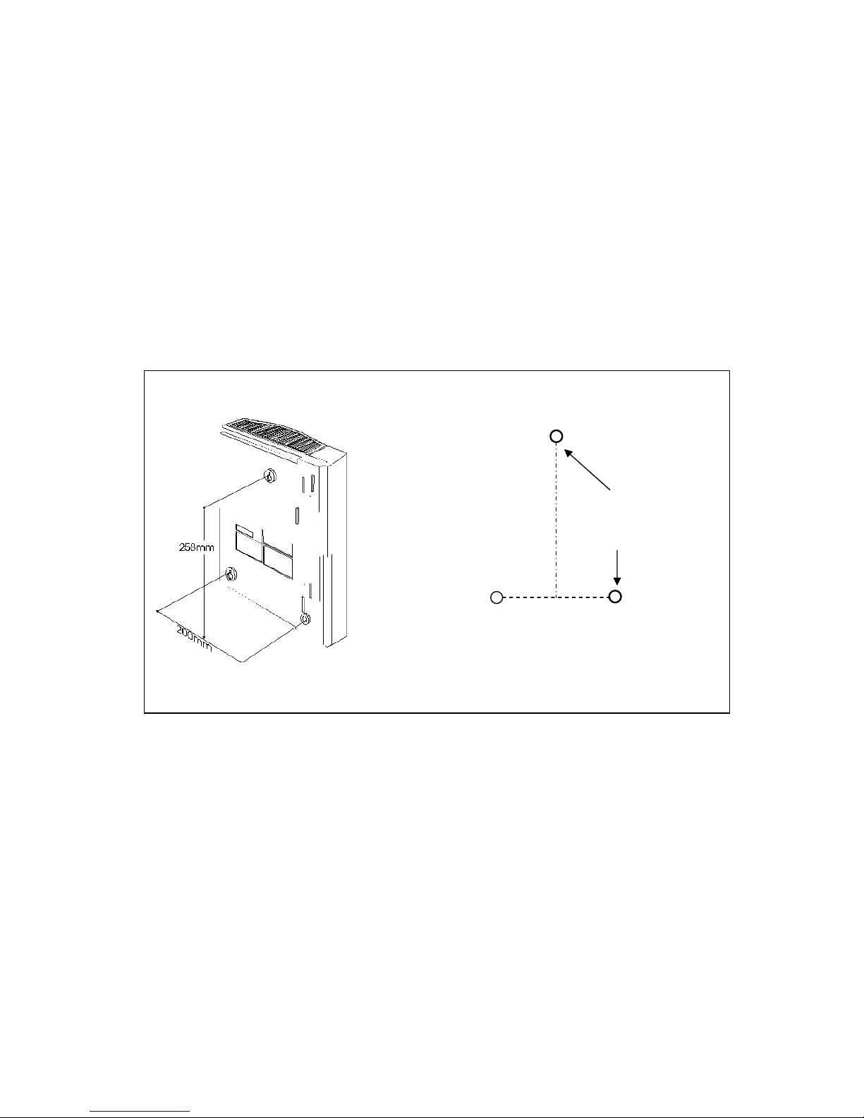
2.1.4 Wall mounting the unit
Follow the steps below to mount the eircom advantage 1200 on the wall. Note that the
mounting screws and rawl plugs are located inside the access area.
1. Mark on the wall the location of the three screw holes using the supplied template.
2. Drill holes and insert rawl plugs.
3. With the Access Cover removed (see previous section), the supporting and the fixing screw
holes are exposed.
4. Insert the two support screws into the support holes and screw down, leaving a 5mm
clearance from the surface of the wall.
5. Place the keyhole slots of the system over the supporting screws.
6. Insert the remaining screw into the fixing hole, via the access area and screw down. DO
NOT OVER-TIGHTEN as this may damage the plastic housing!
The system is now ready for wiring.
Template showing screw hole positions
Fixing Screw
via access
cover
Supporting screw
holes for the key
hole slots

→
→→
→Battery Back-up port
→
→→
→External music-on-hold port
→
→→
→External paging port
→
→→
→RS232 Port via extended cable
Analogue ports (4 a/b extensions)
Numbered 19-22 by default
Digital ports for the connection of
8 Operafone extensions.
Numbered 11 to 18 by default
→Ethernet LAN port
RL1
RL2
→1 RJ-45
→1 cage clamp
3 RJ-45 connectors, permanently
configured for connection of
3 ISDN lines (T-Interfaces)
2.2 Wiring Connections
2.2.1Terminal Connectors in the Access Area
The following diagram illustrates the terminal layout of the eircom advantage 1200. All
terminal connectors are located within the Access Area.
The terminal blocks consist of the following type of connectors:
oCage clamp connectors are used for the connection of back-up battery, relay driven
devices, analogue and Operafone D1 extensions and optional So-Bus Interface.
oRJ-45 connectors are used for the connection of the ISDN Lines, So-Bus Interface and
Ethernet LAN/WAN ports.
oPhono-Jack connectors are used for the connection of the external Music-on-Hold and
Paging units.
oRS232 Connector ( 9 pin female ) is provided via an extended cable from the main board
and is used for call logging equipment requiring a serial interface.
For connection of 4
th
ISDN line
(T-Interface) or 1 Internal So-Bus
2 Relay ports for Doorphone operation
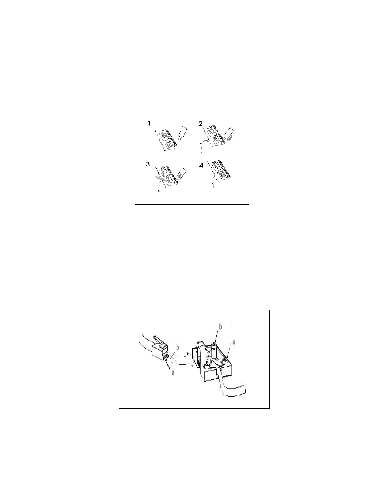
2.2.2 Cage clamp connectors
To connect the wires to the cage clamp connectors, follow the steps below:
1. Insert a non-conducting tool into the groove of cantilever (note that no tool is supplied with
the system)
2. Push cantilever in the direction shown Insert bared wire into the aperture
3. Release cantilever.
2.2.3 Wiring the Extensions
Prepare the wires of the cables and connect them to the appropriate extension terminal blocks
as described above.
Wall-mount the extension telephone sockets. Route the extension cable to the eircom
advantage system observing good building wiring practice by maintaining at least 50mm
clearance between the extension cable and mains power cable, line or other building cable.
System phones and analogue telephones are connected to the system using 2 wires which
should be connected to the a and b terminals.

2.2.4 Function LED’s in the access area
There are 10 function LED’s located in the access area which provide visual indications of the
state of the T interfaces, the ethernet connectivity and the ADSL functionality.
LED No.
Name
Function
LD400
T1
This LED will light if the system detects the presence of a T interface
connected to the T1 socket.
LD300
T2
This LED will light if the system detects the presence of a T interface
connected to the T2 socket.
LD200
T3
This LED will light if the system detects the presence of a T interface
connected to the T3 socket.
LD100
T4
This LED will light if the system detects the presence of a T interface
connected to the T4 socket.
LD800
LNK
This LED will light if the system detects the presence of an ethernet
connection to the LAN port when no DSL module is connected
LD801
COL
This LED indicates a data collision on the data link between the LAN port
and the system
LD300
This LED is now redundant
LD301
This LED is now redundant
LD302
This LED is now redundant
LD303
This LED is now redundant
LD303 LD302 LD301 LD300
LD801 LD800
LD100 LD200 LD300 LD400
DSL Operation
COL
LNK
T4 T3 T2 T1

2.3 Installing the System Phones and DSS Module
The eircom advantage digital key sets, either the Executive or the Standard version, may be
connected to the digital extension ports using single pair cabling. The eircom advantage
system phone line cord is terminated with a male RJ11 plug with pin-out designations as
illustrated in the above diagram.
The eircom advantage Executive and Standard phones can be desk or wall mounted. For desk
mounting the plinth can be fixed to the base in two ways to give high or low viewing angle. The
plinth is fixed to the base of the phone by sliding the tabs on the plinth into the slots on the
phone base.
The Executive and the Standard phone can be wall mounted. To wall mount either system
phone, the plinth is discarded and the phone is fixed using the two screw slots on the base. Fix
the two wall mounting screws 104 mm apart for the Executive phone, 70 mm for the Standard
phone, using the rawl plugs provided.
2.3.1 Connecting the DSS Module
The desktop eircom advantage Executive key set may be equipped with a DSS module for
display of the status of up to 48 system extensions.
To install the DSS module, position the DSS module to the right of the eircom advantage
Executive and turn both upside down. Use the screws supplied with the DSS module to attach
the flange on the DSS module to the lip beneath the cover of the eircom advantage Executive.
Plug the short cable with an RJ11 plug at each end (Executive phone to DSS connect cord),
supplied with the DSS module, into the “phone” socket on the DSS and then plug the other end
of this cable into the eircom advantage Executive “line” socket. Connect the RJ11 plug on the
line cord coming from the Advantage control unit into the “line” socket on the bottom of the DSS
module.
eircom advantage Executive Phone to DSS
Connect Cord
Handset Cord
Screws
Line Co
rd

The DSS keys, numbered 11 to 34 and 41 to 64, automatically act as direct station select keys
for all extensions connected to the control unit.
2.3.2 Programming the Function Keys
Keys associated with unavailable extensions may be programmed for other functions using the
“Redefine Keys” option on the associated eircom advantage Executive key set. Select
“Menus”, “Phone Settings”, “Define Function Key”, “Redefine Keys” and scroll down to, or
press, the key to be defined; its associated led flashes. Select the function to be associated
with the key from the list of options available. Alternatively, the user can program the function
keys from Browser based programming.

2.4 Analogue extensions
The eircom advantage 1200 provides 4 analogue ports in the access area numbered 19 – 22.
Plain, ordinary telephones (Pots) and other approved analogue devices may be connected to
the a/b ports using single pair cabling. Each port is overload and short circuit protected which
provides an additional level of protection when connecting the analogue devices.
2.4.1 Connecting Analogue Phones
The single a, b pair is connected to the analogue terminals ( 19 – 22 ) of the system. All wires
should be inserted securely into the cage clamp terminals ensuring that no exposed copper
wire is visible in the access area. Cable ties on the access area can be used to secure the
wiring cables.
2.4.2 Calling Line Identity (CLI)
The eircom advantage 1200 supports the transmission of CLI (Calling Line Identification)
information to all four analogue extensions.
2.4.3 Recall recognition
Most analogue telephones will have a Recall button ( R ) included on the telephone. This button
is used to generate a hold signal which must be correctly interpreted by the PBX. The eircom
advantage 1200 recognises the Recall signal timings on most commercially available analogue
telphones and by default supports a range from 90 to 120 msec (approx)
2.4.4 Analogue Extension electrical characteristics
The electrical characteristics of the analogue extensions on the eircom advantage 1200 are
listed below.
Analogue extension electrical characterstics
On-Hook Voltage 48 Volts
Off-Hook Voltage 8 Volts
Ringing Voltage 64 V (RMS)
Ringing frequency 25 Hz
Busy Tone Timing 500 ms ON 500 ms OFF
The eircom advantage 1200 supports high impedance connections to the analogue extension
ports allowing substantially long cable lengths to be used. To provide for an extra long cable
connection on one of the ports, extension 19 accomodates almost five times the impedance of
the other ports as shown in the table below.
Extension
Impedance
Extension Cable Length (*)
19
1000 Ohms 5.95 Km
20
204 Ohms 1.2 Km
21
204 Ohms 1.2 Km
22
204 Ohms 1.2 Km
(*) These figures assume that 0.5 mm copper conductor cable is being used to connect the
analogue extensions.

2.5 Internal/External (S/T) ISDN basic access Interface
The eircom advantage 1200 offers 3 RJ-45 connectors permanently configured as T (Line)
interfaces, while the fourth can be configured by the user as either a T or an internal So Bus (S
Interface).
For your convenience, the system provides two connectors that allow the connection of the So-
Bus: an RJ-45 connector and a cage clamp connector. You may connect to one or the other
depending on the type of cabling you wish to route.
Configuration of the So-Bus takes place by moving the plastic shunt on the JP39 Jumper to the
lower positoin on the pins as shown below. (This switches the Transmit and Receive pair
positions on the connector as well as inserting/disinserting the 40 Volts DC Power Feed for the
Terminals on the S-Bus).
So Bus Connectors
Cage clamp
RJ45
JP39
JP39
T Shunt position on top for T interface
S Shunt position below for So Interface
The S-bus option, if required, must be enabled in Browser Based Programming.
The So-Bus is a 4-wire bus to which up to 8 ISDN terminals may be connected and operates
only in Point to Multipoint mode.
So Bus connections to the cage clamp
Male-Male RJ45 Cable
To connect the So-Bus, just plug the male RJ-45 cable connector into the RJ-45 terminal
connector of the access area. If you are connecting the So-Bus to the cage clamp connector,
then check the diagram above for pin connections.
Rx Pin 3
Tx Pin 4
Tx Pin 5
Rx Pin 6

2.6 Connecting ISDN lines
The system allows the connection of up to 4 ISDN lines (T-Interfaces), one of them being
configurable as an internal So-Bus as explained above. A Male-Male RJ45 cable is needed to
connect each ISDN line. The system may be configured to operate in either Point to Point
mode or in Point to Multipoint mode.
An eircom Business systems technican may change the line mode to Point to Point or Point to
multipoint from Browser based programming.
Note: If the eircom advantage 1200 is to be connected in a Point to Multipoint configuration, it
MUST be installed as the last terminal on the bus. If the system is connected in a Point to
Multipoint configuration and is NOT installed as the last terminal on the bus then the jumpers
associated with the line ( shown below ) must be removed.
T Interface
Jumpers
T1
JP1 & JP2
T2
JP3 & JP4
T3
JP5 & JP6
T4
JP7 & JP8
JP2 JP1
JP4 JP3
JP8 JP7
JP6 JP5
S/ T4 T3 T2 T1
Main Board
Access Area
Table of contents
Other Eircom Telephone manuals


