Eisco CH0814 User manual

Instruction Manual
WATER STILL
CAT NO. CH0814
ASSEMBLY & OPERATING INSTRUCTIONS
MOUNTING & PLACEMENT
This equipment can be wall mounted or bench mounted.
ENVIRONMENTAL CONDITIONS
* For indoor use only statement: Water Still is designed for reliable
continuous operation incorporating a host of features unmatched by
comparable stills. It is Easy to Use, Portable, Safe to Operate and
thoroughly reliable, i.e., the reason it is recommended for indoor use
only.
* Ambient Temperature +5°C to 40°C
* Altitude : Up to 2000 meters
* Relative Humidity : Not exceeding 80%
* Electrical Supply :
* :
:
* Impairment statement :- If the equipment is not used in the manner
may be impaired. Please read the manual carefully before installation
or operating the unit.
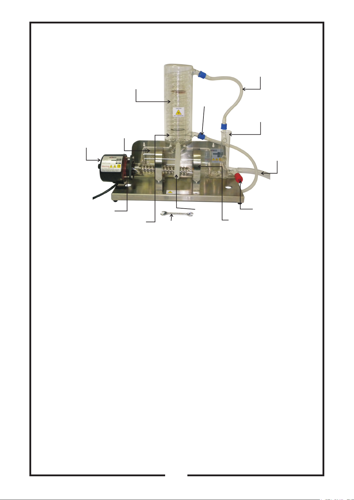
Condenser
Cooling water
Inlet
Boiler
Heater
Gaskets & Clamp
Vent Straps
Drain cock
To Drain
Constant Level
Control
Boiler Inlet
Key
Distillate
Outlet
-1-
© EISCO SCIENTIFIC ●www.eiscolabs.com
:
220-240VAC, 50Hz, Single Phase
Pollution Degree 2 According to IEC 60664
*
Over Voltage Category Category II According to IEC 60664
described in the manual the protection provided by the equipment
IP IP20
:
*
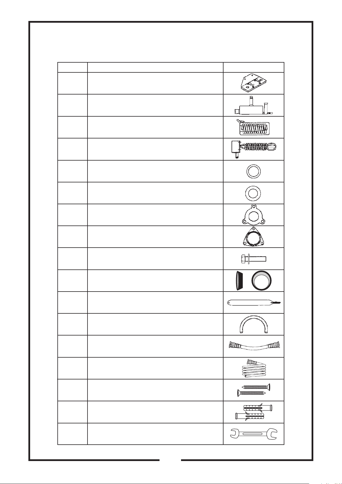
PART LIST OF PURE HILL STILL
Part No. Description Diagram
S.S. Stand
Glass Boiler
Glass Condenser
Metal Heater (with reset able)
Silicon 'O' Ring
Silicon 'O' Ring
Neoprene Rubber Gasket
Metal Flange
Stainless Steel Bolt for Heater
Rubber Collar Insert
Stainless Steel Boiler Straps with
Springs
PVC drain Tube
Silicon Tubing with threaded plastic
connector
Silicon Tubing with plastic connector
16.
1.
2.
3.
4.
5.
6.
7.
8.
9.
10.
11.
12.
13.
14.
15.
17.
Self Tapping Screw
Plastic Gitti
Spanner
10
11
-2-
© EISCO SCIENTIFIC www.eiscolabs.com
PH/BSSS
PHB/B4
PHC/B4
PH/H/3KW
PH/HK
PH/GK
Order No. for spares
1
1
1
1
1
1
Quantity
Component
S.S. Stand with 2 stainless steel boiler
straps with springs (Part 1 & 11)
Glass Boiler (Part No. 2)
Glass Condenser (Part No. 3)
Metal Heater (Part No. 4)
Hose Kit (Part No. 12, 13, 14)
Gasket Kit (Part No. 5, 6, 7, 8, 9, 10)
CHECK FOR THE FOLLOWING SERVICES
* Single phase electric supply capable of handling a load of 3KW, 230V
± 10%, 50 Cycles and with a fuse carrier of 13 amps. Supplies should
be fitted with a 30mARCD circuit breaker.
* A conventional 13 amps plug and socket, wall mounted is
recommended.
* The equipment must be earthed in all cases. Red - Live, Black-
Neutral and Green - Earth.
* Cooling water supply for Glass Condenser (Part No. 3) capable of
providing minimum flow rate of 60 ltrs/hr. The flow rate has to be
adjusted by the lab technician using a measuring cylinder or using a
flow meter.All water supplies should be earth bonded.
* A drain located below the level of the still so that the PVC Drain pipe
(Part No. 12) from the Glass Boiler (Part No.2) can fall straight without
kinks or bends to allow unimpeded flow of water. Ensure all drainage
systems are earth bonded.
* Reservoir :-Adistillate collection reservoir should be below the output
of still.
INSTALLATION
1. Open the box carefully and identify the following components:
2. Place the S.S. Stand (Part No. 1) at a suitable location, bench top ro
wall mounted using the two key holes provided.
-3-
© EISCO SCIENTIFIC ●www.eiscolabs.com
3. Take the Glass Boiler (Part No. 2) ensuring that the two Silicon rubber
'O' rings (Part No. 5) on the vapour tube are in place. The smaller
silicon rubber 'O' ring (Part No. 6) to be seated on the top groove of
the vapour tube of the Glass Boiler (Part No. 2). The bigger silicon
rubber 'O' ring (Part No.6) is to be adjusted to a distance of approx.
35mm from the top surface of the Glass Boiler (Part No. 2) or such
that when the Glass Condenser (Part No.3) is placed over the vapour
tube it does not shake. Take the metal Heater (Part No. 4) the Metal
Flange (Part No.8) the Neoprene Rubber Gasket (Part No.7) and the
Rubber Collar Insert (Part No. 10) and assemble as shown in the Fig.
No. 1.
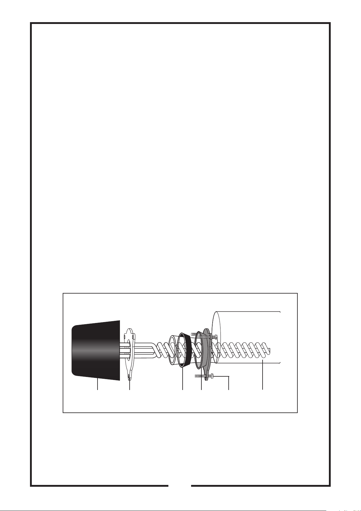
(a) Place the Metal Flange (Part No. 8) (Flat side facing the Boiler) over
the tapered Glass neck of the Glass Boiler. (Part No. 2).
(b) The Rubber Collar Insert (Part No. 10) is bent around the tapered
Glass neck and into the Metal Flange (Part No. 8). The Metal Flange
(Part no. 8) is pulled and inserted towards the end of the Glass Boiler
(Part No. 2) neck so that when the Metal Flange (Part No. 8) is pulled,
the Rubber Collar Insert (Part No. 10) seals on the neck.
(c) Place the Neoprene Rubber Gasket (Part No. 7) over the metal
heater (Part No.4) and insert the metal heater (Part No. 4) through the
tapered Glass neck and into the Glass boiler (Part No. 2).
(d) Secure the Metal Heater (Part No.4) with the three Stainless Steel
Bolts (Part No. 9) provided. Care should be taken not to over tighten
the bolts. The heater axis should be parallel to the boiler axis.
4. Place the Glass Boiler (Part No. 2) and Heater assembly in the cradle
of the powder coated stand (Part No. 1) It plug not installed connect
the Metal Heater (Part No. 4) cables to the pins of the 13 amps
connector as per circuit diagram page. 9.
-4-
© EISCO SCIENTIFIC ●www.eiscolabs.com
FLANGE ASSEMBLY
Boiler
S.S.
Bolt
Metal
Flange
Rubber
Coller
Insert
Neoprene
Rubber
Gasket
Metal
Heater
Fig. 1

5. Mount the Glass Condenser (Part No. 3) onto the vapour tube of the
Glass Boiler (Part No.2). The distillate outlet tube or vent should face
the front.
11. Connect the distillate outlet on the Glass Condenser (Part No. 3) to a
suitable collection reservoir with the help of Silicon tubing with plastic
connector (Part No. 14)
12. Connect the mains of the Metal Heater (Part No. 4) to a fused 13 amp
electric supply capable of providing a load of 3KW at 230V ± 10% 50
cycles single phase.
IMPORTANT : THE EQUIPMENT MUST BE EARTHED
STARTING THE WATER STILL
1. Turn on the cold water supply and adjust the flow rate to
approximately 60ltr/hr. Allow the water to flow via the Glass
Condenser (Part No. 3) into the Glass Boiler (Part No. 2). When the
water level reaches the correct operating level and excess water
flows to the drain, turn on the heater.
2. When the boiling commences and the distillate emerges from th
Glass condenser (Part No. 3) start collecting in the reservoir.
6. Take the silicon tubing with Screw thread connectors at either end
(Part No. 13). Screw one end of the silicon tubing on to the upper
outlet of the Glass Condenser (Part No. 3) and the other end to the
Glass thread on the Glass Boiler (Part No. 2) inlet.
7. Take the PVC Drain Pipe (Part No. 12) and connect to the drain of the
Glass Boiler (Part No. 2).
8. Lead the free end of the PVC Drain Pipe (Part No. 12) to the drain.
Ensure that there are no kinks or bends in the tube so that water flow
is not impeded.
9. Ensure that the Teflon drain cock on the Glass Boiler (Part No. 2) is
closed.
10. Connect the cooling water inlet of the Glass Condenser (Part No. 3)
to the cold water feed supply through the hose provided. For easy
attachment to the Glass Condenser (Part No. 3) a plastic screw
thread is provided along with the hose.
-5-
© EISCO SCIENTIFIC ●www.eiscolabs.com
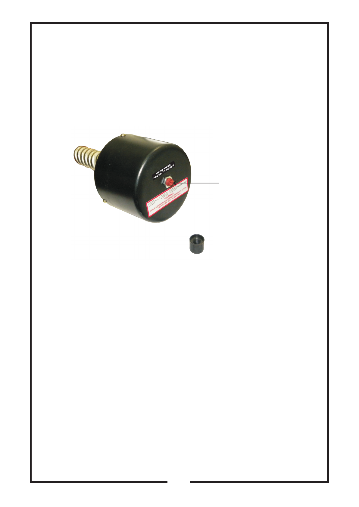
SAFETY CUT OUT
A thermostat is provided with the Metal Heater (Part No. 4) to protect the
still from accidental failure of the water supply. When the Glass Boiler (Part
No. 2) runs dry, the thermostat automatically shuts off the metal heater
(Part No. 4) to reset open the knob on top of cap and push the lever down
as shown in picture the thermostat.
CLEANING
Over a period of operation, scale deposits may develop inside the Glass
Boiler (Part No. 2) For peak performance from you still it is necessary to
clean the Glass Boiler (Part No. 2) regularly.
The number of times the still needs to be cleaned during the course of its
operation depends on the hardness of the water used. In very hard water
areas it might be necessary to clean the still once a week, while in soft
water areas several weeks may elapse before cleaning becomes
necessary. 10% formic acid (mechanic acid or Kettle descale) is used for
removing scale deposits. Do not use strong acids such as hydrochloric
acid, because it can damage the metal heating element.
CARE AND MAINTENANCE
For prolonged life of the still it is necessary that regular care and
maintenance should be taken. Before any maintenance operation, the still
must be isolated from the mains electric supply.
Push to Reset
-6-
© EISCO SCIENTIFIC ●www.eiscolabs.com

PROPER PRECAUTIONS MUST BE TAKEN DURING
HANDLING OF ACIDS.
STEPS ON CLEANING
1. The electric supply to the still is switched off and the water in the
Glass Boiler (Part No. 2) is allowed to cool.
2. The cooling water supply is turned off.
3. The Teflon drain cock is the Glass Boiler (Part No. 2) is opened and
the water in the Glass Boiler (Part No. 2) is completely drained off.
The drain cock is the closed.
4. Through the funnel of the Glass Boiler (Part No. 2) inlet tube fill dilute
10% formic acid solution till the operating level is reached. Excess
acid should be avoided.
5. The acid is allowed to react and break down the scale deposits. The
time taken depends on the severity of scale build up.
Important : Safety precautions have to be observed since the liquid
flowing to the drain may be acidic as it may not be completely
neutralized.
6. The drain cock in the Glass Boiler (Part No. 2) is closed and the Glass
Boiler (Part No.2) is filled with cold water and allowed to drain out.
This procedure is repeated two or three times.
7. The still can be restarted when the Glass Boiler (Part No. 2) is filled
with water. The still should be allowed to run for around 10 minutes
before collecting the distillate.
REGULAR CLEANING WILL KEEP YOUR STILL RUNNING AT
OPTIMUM CONDITION.
-7-
© EISCO SCIENTIFIC ●www.eiscolabs.com

TROUBLE SHOOTING
Incase of any operating difficulties with the still the following tips may help.
Warning :- Please ensure that electrical connections are
disconnected before opening the Heater cup.
-8-
© EISCO SCIENTIFIC ●www.eiscolabs.com
S. No. SYMPTOM CAUSE REMEDY
1Distillate rate less
than 4ltr/hr.
2
3
4a
4b
4c
5a
5b
6a
6b
7a
7b
7c
8a
8b
Distillate
temperature high
Distillate quality poor
Water in Glass Boiler
(Part No. 2 is pumped
out of Glass Boiler of
drain.
Water level in the
Glass Boiler is too
high e.g.,boiling water
surging into Glass
condenser (Part No.3)
Water level in Glass
Boiler (Part No.2) is
too low e.g., Metal
Heater (Part No. 4)
exposed
Metal Heater
(Part No.4) Not
working
Metal Heater
(Part No.4)repeatedly
cycles On & Off
Mains electric supply
below 230V±10%
Flow of cooling water in Glass
Condenser (Part No. 3) not adequate
Glass Boiler (Part No. 2) heavily
scaled
Vent on Glass Condenser
(Part No. 3) distillate outlet is blocked
Silicon tubing with plastic connector
(Part No. 14) from Glass Condenser
(Part No. 3) distillate outlet to
reservoir is constricted.
Supply of feed/cooling water is
insufficient
Flow of drainage water is constricted
Supply of feed/cooling water is
excessive
Drain cock on Glass Boiler
(Part No. 2) inadvertently left open
Supply of feed/cooling water is
insufficient
Burnt out Metal Heater (Part No. 4)
Mains electric fuse blown
Faulty thermostat
Faulty thermostat
Thermostat not operating
Ensure sufficient power
supply
Increase flow rate of
water to approx. 60ltr/hr
Clean Glass Boiler
(Part No. 2)
Ensure that Silicon tubing
with plastic connector
(Part No. 14) falls freely
without any kinks or
bends
Increase flow rate to
approx. 60ltr /hr.
Ensure PVC Drain pipe
(Part No. 12) falls freely
without any kinks or
bends
Remove Blockage
Reduce flow rate of water
Approx. 60ltr/hr.
Close drain cock in the
Glass Boiler (Part No. 2)
Increase flow rate to
Approx. 60ltr/hr.
Replace Metal Heater
(Part No. 4)
Replace fuse
Replace thermostat
Replace thermostat
Reset

REPLACEMENT OF FAULTY PARTS/COMPONENTS
Metal Heater (Part No. 4) Replacement:
1. The Metal Heater (Part No. 4) is turned off and the still is
disconnected from the mains electric supply.
2. The Glass Boiler (Part No. 2) is cleaned if heavy scaling is present by
the following cleaning procedures detailed in this manual.
3. It is easier to replace the heater by working with the Glass Boiler on
the bench
* Remove the Glass Condenser (Part No. 3)
* Drain the Glass Boiler (Part No. 2) via drain cock
* Remove the Glass Boiler (Part No. 2) complete with Metal Heater
(Part No. 4) from the S.S. stand (Part No. 1)
* Unscrew the three stainless steel bolts (Part No. 9) securing the
Metal Heater (Part No. 4) to the Glass Boiler (Part No. 2)
* The new Metal Heater is fitted to the Glass Boiler by following the
installation instructions - 3
4. The still is reassembled by following the installation instructions 4 -
12.
CIRCUIT DIAGRAM
-9-
© EISCO SCIENTIFIC ●www.eiscolabs.com
GREEN
BLACK
RED

THERMOSTAT REPLACEMENT
The thermostat is located within the Metal Heater (Part No.4) and may
easily by replaced by following these instructions.
1. The metal heater (Part No. 4) is turned off
and the still is isolated from the mains
electric supply.
2. The three small retaining screws holding
the plastic cup is place is removed (Not
the three bolts securing the Heater to the
Boiler).
3. Referring to the wiring diagram, the two
wires to the thermostat are disconnected.
4. The thermostat is removed from the
Heater pocket.
5. The new thermostat is placed in position and the electrical
connections are made.
6. Check whether the thermostat is set of 125°C.
7. Replace the Metal cover of the Heater.
-10-
© EISCO SCIENTIFIC ●www.eiscolabs.com
RED
BLACK
RED
GREEN
BLACK
RED
Wiring Detail
Green : Earth
Black : Neutral
Red : Live
Thermostat
ENVIRONMENTAL CONDITIONS
1. Pollution Degree: 2
2. Installation Category: 2
3. Altitude: 2000 meters Max.
4. Electrical Supply: 220V - 240V AC, 50Hz
5. Equipment is meant for Indoor use only
6. Ambient Temperature: 40°C Max.

U.S. Distributor:
Eisco Scientific
788 Old Dutch Road, Victor, NY 14564
Website: www.eiscolabs.com
EISCO SCIENTIFIC instrucons, content and design is intellectual property of EISCO
Manufactured by :
www.eiscolabs.com
Table of contents
Other Eisco Laboratory Equipment manuals


Popular Laboratory Equipment manuals by other brands

Heathrow Scientific
Heathrow Scientific Vortexer HS120209 instruction manual

Okolab
Okolab H301-KEYENCE-BZX user manual

BioLAB
BioLAB BIFL-205 Operation manual

NSW
NSW Caltan NSW-227 Maintenance manual

World Precision Instruments
World Precision Instruments PUL-1000 instruction manual

Heidolph
Heidolph REAX 2 instruction manual

Amerex
Amerex Hirayama HG-50 Operation manual

HACH LANGE
HACH LANGE AMTAX inter2 Basic user manual

IKA
IKA ULTRA -TURRAX Tube Drive P control operating instructions

Minebea Intec
Minebea Intec PR 57 installation manual

Wyatt Technology
Wyatt Technology Optilab rEX user guide

Primerdesign
Primerdesign genesig q16 instruction manual


