manuals.online logo
Brands
  1. Home
  2. •
  3. Brands
  4. •
  5. EisSound
  6. •
  7. Stereo System
  8. •
  9. EisSound i500 User manual

EisSound i500 User manual



Multiroom Audio System

L







 ,167$//$7,210$18$/
Multiroom Audio System

L

LQVWDOODWLRQPDQXDO







1.- Description and components of the i500 Series 3
2.- Pre-installation: previous recommendations 5
2.1.- Power Source 5
2.2.- Communication Line 5
2.3.- Line Reinforcement Module 5
2.4.- FM Tuners 6
2.5.- Coverage of Remote Control Unit 6
3.- Installing the Master Unit 8
3.1.- Connection to Communication Line 8
3.2.- Connection to Universal Dock for iPod 9
3.3.- Connection to External Sound Sources 9
4.- Installing Speakers in each zone 11
4.1.- Basic Installation 11
4.2.- Extended Installation 11
5.- Installation configuration 13
5.1.- Install each Main Speaker with its own Remote Control Unit 13
5.2.- Install several Main Speakers with the same Remote Control Unit 14
5.3.- Incorporate a new Remote Control Unit to the current System 15
5.4.- Other configuration options 18
6.- Reset the system with factory default settings 20
7.- Technical Characteristics 21
8.- Quick Reference Guide for Remote Control Unit Operation 23
Recommendations to achieve enhanced communication between the Remote
Control Unit and the Main Speaker 24
 
iPod is trademark of Apple Inc. registered in teh U.S. and other countries
"Made for iPod" means that an electronic accessory has been designed to connect specifically to iPod and has been certified by
Electrónica Integral de Sonido S.A. to meet Apple performance standards.
Apple is not responsible for the operation of this device or its compliance with safety and regulatory standards
Electrónica Integral de Sonido S.A. is not responsible for any error or omissions that may appear in this manual, and reserves the right to
make changes without prior notice.
  


 'HVFULSWLRQDQGFRPSRQHQWVRIWKHL6HULHV
The i500 is a multi-room audio system for listeners to enjoy music throughout the entire home
by integrating the sound into the home’s fixtures. Thanks to its built-in ceiling speakers, the
i500 does away with the need for portable MP3 devices or individual sound systems in each
room. The Series is also equipped with intercom features for room-to-room communication,
electronic baby monitors, etc.
Some of the i500 Series features:
Enjoy music throughout the entire house
Access different music channels, including a disc player and an iPod docking station
with full control allowing the user to navigate throughout a full collection of music
Wireless Remote Control Unit
The i500 Series does not require hook-up from a dedicated computer. No technical computer
skills are required to fully enjoy all the features equipped to the system.
With the i500 Series it is possible to distribute different music channels to as many as 32
separate rooms from a Master Unit.
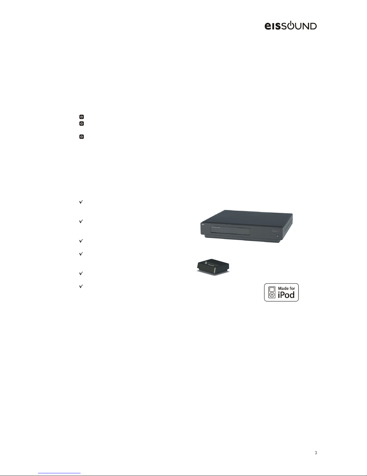
The Master Unit (ref. 51121) is equipped with the basic features:
FM tuner with built-in RDS and RF
75 ohm coaxial connectors for
antenna
CD/DVD disc players able to
“reproduce” audio CD, CD-MP3 and
DVD-MP3
connection to Universal Dock for
iPod (ref. 52222)
Two RCA inputs for external sound
devices with independent regulator
and level indicator
Data and sound (4 channels)
output line via RJ45 connector
Direct connection to the electrical
power source (110 to 240Vac/35W)
ref.51121
ref.52222
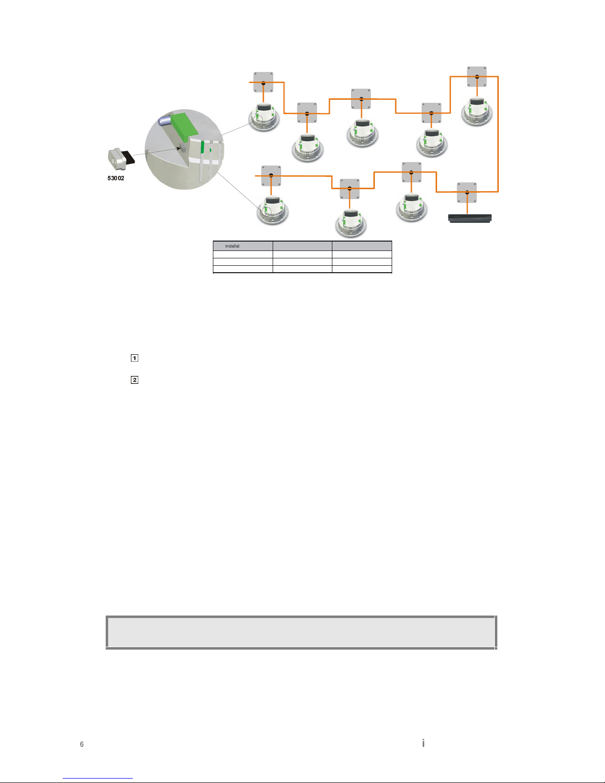
A Main Speaker (ref. 55101) and a Passive Speaker (ref. 55301) are installed in each zone or
room. Flush-mounted in the ceiling, they become integrated into the home without the need for
entertainment centers, counters or any other type of external fixture
A bus-type cable connection is required to communicate the Master Unit with all the Main
Speakers within the system. The wired connection provides optimal sound quality reception,
free of interference and interruptions, thus guaranteeing total privacy from possible intrusions
(involuntary or intentional) from outside the home.
The Main Active Speaker (ref. 55101) integrates the control and sound electronics of each zone
or room and is equipped with the following basic features:
Multiroom Audio System

L

LQVWDOODWLRQPDQXDO
FM tuner with built-in RDS and 75
ohm RF coaxial antenna connector
Wireless data and sound
communication with 52121 Remote
Control Unit
Data and sound (4 channels) input
line from the Master Unit: 8 wires
5+5W sound amplifier
Built-in two-way loudspeaker
8 ohm output for Passive Speaker
(ref. 55301)
Line output (4 wires) for Auxiliary
Active Speaker (ref. 55201)
Connection to the electrical power
source (110 to 240Vac/20W)
ref. 55101
The Auxiliary Active Speaker (ref. 55201) is ideal for zones or rooms where greater sound
power is required. Its features include:
5+5W sound amplifier
Built-in two-way loudspeaker
8 ohm output for Passive Speaker
(ref. 55301)
Line input (4 wires)
Connection to electrical power
source (110 to 240Vac/18W)
ref. 55201
The entire system is handled from Remote Control Units (ref. 52121). They do not require any
installation. The Remote Control Unit Base (ref. 52221) needs be connected to the mains,
acting as the remote’s platform as well as providing battery charge for the Remote Control Unit:
Graphic interface with 2.2” color TFT
Built-in microphone
3.5 mm input jack for external sound
source
Wireless data and sound communication
with Main Active Speaker (ref. 55101)
Battery charger connected to the
electrical supply (110 to 240Vac/5W)
ref. 52121 (Remote Control Unit)
ref. 52221 (Remote Control Base)
2QO\XVH%DVHWRFKDUJH5HPRWH&RQWURO8QLWPRGHOEDWWHULHV

  



 3UHLQVWDOODWLRQ
 SUHYLRXVUHFRPPHQGDWLRQV
The i500 Series requires basic pre-installation. To avoid future issues and ensure optimal
system operation, follow these prior recommendations.
 3RZHU6RXUFH
Power source wires should be compliant to regulations in force.
It is recommended that the power source to Master Unit (ref. 51121),
Main Speakers (ref. 55101) and Auxiliary Active Speakers (ref. 55201)
be from the same automatic switch in order to facilitate isolation and
disconnection of the sound system independent from the rest of the
home’s electrical consumption. This will also avoid signal reception and
sound interference with other appliances such as extractor fans, air
conditioning, refrigerators, fans and the like (see wiring diagram in
Chapters 3.1, 4.1 and 4.2).
,03257$17GRQRWVXSSO\SRZHUWRWKHV\VWHPXQWLOLWLVFRUUHFWO\LQVWDOOHGDQG
FRQQHFWHG
 &RPPXQLFDWLRQ/LQH
The communication line (ref. 57101) is an 8 wire connecting hose that connects Master Units
(ref. 51121) to all Main Speakers (55101)
To make connection 4 (yellow) use 1mm2cross-section wires. For the remaining connections
use 0.25mm2cross-Section wires. It may be necessary to increase the wire cross-Section in
systems with a large number of units and/or great distances. In this case consult with EIS
Technical Services.
Bus-type communication line distribution is necessary to keep the length of the shunts to each
Main Speaker (“stub”) to the minimum. This is especially important in systems greater than 100
meters and/or ten Main Speakers. In smaller systems star or mixed connections are possible.
 /LQH5HLQIRUFHPHQWPRGXOH
It may be necessary to use a Line Reinforcement module (ref. 53002) in some cases. This
module would be pluged in the Main Active Speaker (ref. 55101)
The location of the device is very important:
In a bus-type system it should be installed in one or both ends of the system (see the
figure)
In star or mixed type systems look for the longest straight path between two points and
install the device on one or both ends of the system.
Multiroom Audio System

L

LQVWDOODWLRQPDQXDO

installation length
# Main Active Spk. (55101)
# Line Reinf.Device (53002)
0..100m 0..10 0
100..200m 10..20 1
200..600m 20..32 2

)07XQHUV
Installation of the 75 ohm FM antenna must be according to adequate techniques of installation
and signal distribution for antennas:
Ensure that the FM band amplifier is in the header of the antenna installation
The installation should include as many distributors as necessary to reach all antenna
feeds in the Master Unit and Main Speakers.
Because RDS information reception is more demanding in terms of signal/noise proportion than
a simple FM signal, in some areas where signal reception is not optimal it may not be possible
to receive RDS information. Also not all stations broadcast RDS information so the RDS
function may not always be available.
In areas of very strong FM signal reception the antenna may be replaced by a simple 76cm long
wire inserted into the nucleus of the ANT connector. In this event the wire should be placed as
far away as possible from sources of electromagnetic interference such as motors, contact
units, relays, fluorescents, halogens, and the like.

&RYHUDJHRI5HPRWH&RQWURO8QLW
The entire system is solely and uniquely operated by using the 51121 Remote Control Units
installed in each of the zones or rooms included in the system.
It is VERY IMPORTANT to carefully choose the location AND ORIENTATION of the Main
Speaker when planning the pre-installation.
7KH0DLQ$FWLYH6SHDNHUUHILVYLVXDOO\GLVWLQJXLVWDEOHIURPWKHUHVWRIWKH
6SHDNHUVE\WKHEOXH/('HPEHGGHGLQWKHIURQWJULOO
  


Place the Main Speaker in a preferential location in the room, as clear from any obstacles
as possible, especially metallic objects.
Position the Main Speaker in way that the LED is facing the Remote Control Unit.

P
P
P P
The location of the remaining Speakers (Auxiliary Active Speakers 55201 and Passive
Speakers 55301) does not affect the coverage of the Remote Control Unit.
7RIDFLOLWDWHFRPPXQLFDWLRQEHWZHHQWKH&RQWURO8QLWDQGWKH0DLQ6SHDNHUIROORZDOO
WKHUHFRPPHQGDWLRQVLQFKDSWHU
Multiroom Audio System

L

LQVWDOODWLRQPDQXDO
 ,QVWDOOLQJWKH0DVWHU8QLW

 &RQQHFWLRQWR&RPPXQLFDWLRQ/,1(
The Master Unit (ref. 51121) is connected to the communication line by means of a Line
Connector module (ref. 573x1). The cable supplied with the Master Unit must be specifically
used for this connection.
The Line Connector module is available in several colours and can be connected to leading
market switch brands by using the adapters listed in the EIS catalog (BJC, Jung, Legrand,
Niessen, Schneider, Simón, bTicino, ...).
Connection to the power supply is made with the cable supplied with Master Unit (see
installation recommendations in Chapter 2.1).
The Master Unit has a 75 ohm antenna input for FM tuner which is built-in (see Chapter 2.3).
59
57
58
4
54
53
52
51
   
  
  
  
   !
  " 
# 
$    
%'& (*)

[
L N
230V

4
%'& (*)
   
  
  
  
   !
  " 
# 
$    
  

+

 &RQQHFWLRQWR8QLYHUVDO'RFNIRUL3RG
To access music stored in an iPod, the Master Unit (ref. 51121) is equipped with a back panel
connection to the Universal Dock for iPod (ref. 52222). The connection is only available with
this unit and should not used for any other purpose.
, - . - ,
, - . - ,
/ 0 1 2 3 4
/ 5
/ 6
7 8 9
: ; < =
0
<
>
 &RQQHFWLRQWR([WHUQDO6RXQG6RXUFHV
On its back panel, Master Unit (ref. 51121) is equipped with 2 RCA inputs to connect 2 external
sound sources as L1 and L2.
([WHUQDO/VRXQGLQSXWVKDUHVLJQDOZLWKL3RGZLWKWKLVRQHDVSULRULW\7KDWPHDQV
WKHPXVLFLQE\/LVRQO\DYDLODEOHZKHQL3RGLVQRWFRQQHFWZLWKWKHGRFN
The maximum allowable length for this connection depends on the external devices that supply
the signal (consult the manufacturer’s technical specifications). The length tends to vary
between 1 and 10m. The input signal level can be adjusted using a potentiometer together with
a LED.
? @ A @ ?
? @ A @ ?
B C D E F G
B H
B I
J K L
M N O P
C
O
Q
There are three alternatives for connecting an external sound source to the Master Unit:
(1) Preferably use the music system line out as an external sound source. This output
ensures a constant signal which is independent of the system’s volume control.
L
LINE OUT
R
Multiroom Audio System

L
RTS
LQVWDOODWLRQPDQXDO
(2) In systems equipped with a REC OUT (such as HI FI systems), connection to the
51121 Master Unit can be installed between the REC OUT and the music system’s
amplifier.
L
TAPE
OUT IN
R
L
REC
IN OUT
R
(3) The headphone output can be used in systems with no LINE OUT or REC OUT (such
as walkman, compact stereos, MP3 players …). This output is regulated by the
system’s volume output and must therefore be adjusted with the level potentiometer on
the 51121 Master Unit to achieve the ideal signal level.
  

RR

 ,QVWDOOLQJ6SHDNHUVLQHDFK]RQH
,QFKRRVLQJWKHORFDWLRQRIWKH0DLQ6SHDNHULWLV9(5<,03257$17WRIROORZDOO
UHFRPPHQGDWLRQVLQGLFDWHGLQ&KDSWHU

 %DVLFLQVWDOODWLRQ
Each Main Active Speaker (ref. 55101) requires simple installation as per the following diagram.
4
UV WYX
4
Z\[^]
L
N
Z*W`_
abdc e f
g h ikjl
m c n h fe
g o npq
ro i q sf
g h t f
uo fdf q
v fh h np


230V

L
N
2
3
0
V

 ([WHQGHGLQVWDOODWLRQ
In zones or rooms where more than two speakers are required it is possible to add as many
pairs of Auxiliary Active Speaker (ref. 55101) + Passive Speaker (ref. 55301) as desired to
cover the entire sound system area.
Multiroom Audio System

L
wTx
LQVWDOODWLRQPDQXDO
4
yz
{
L
N
|
|
}~

|
|
~

4
y
z
{
L
N
|
|
}
~

|
|

~

4


4
yz
{
L
N
y


|
|

~

|
|

~

230V
|

~

230V
2
3
0
V
L
N
230V
 

  


 


















  

wT
 ,QVWDOODWLRQFRQILJXUDWLRQ
,QWKHIROORZLQJSURFHVVLWLVDVVXPHGWKDWDOOWKHXQLWVDUHQRWLQVWDOOHGDQGVWLOO
XQGHUIDFWRU\VHWWLQJV7RUHVHWWKHV\VWHPWRIDFWRU\GHIDXOWVHWWLQJVVHH&KDSWHU
 ,QVWDOOHDFK0DLQ6SHDNHUZLWKLWVRZQ5HPRWH&RQWURO8QLW

6XSSO\LQJSRZHUWRWKHV\VWHP
Engage the automatic switch that
feeds the power to all system
components. 
Review that Master Unit and ALL Main Speakers emit a SLOW FLASHING signal to
indicate that they are NOT INSTALLED.
not installed
Wait 10 seconds minimum with the installation un-powered before supplying power to
the system
6XSSO\LQJSRZHUWRWKH5HPRWH&RQWURO8QLWV
Use a tool to open the battery compartments in the
Remote Control Units and insert the batteries being
careful to align the polarity correctly. Only use the
rechargeable batteries supplied with the product
(AAA NiMH 1,2V). Do not discard used batteries
mixed with household waste
Place the Remote Control Units in their respective Remote Control Bases and connect
them to any electrical outlet in the home (it is not necessary for these outlets to be
controlled by the automatic switch of the rest of the system elements of 51121 Master
Unit, 55101 Main Speakers and 55301 Auxiliary Active Speakers.)
The Remote Control Unit displays the initial screen, pending start up of the installation
process.
battery
Multiroom Audio System

L
w^¡
LQVWDOODWLRQPDQXDO
The Remote Control Unit can be operated while stationed in the base. It is
recommended that the remote NOT BE SEPARATED FROM THE BASE until the
batteries are completely charged.
$VDJHQHUDOUXOH,7,65(&200(1'('WKDWZKHQQRWLQXVHWKH5HPRWH
&RQWURO8QLWEHLQVHUWHGLQLWV%DVH
/LQNHDFK5HPRWH&RQWURO8QLWZLWKLWVRZQ0DLQ6SHDNHU
The Remote Control Unit together with the Main Speakers use a single "home address"
which ensure that the system operates independently and free of any other i500
systems installed in neighboring homes. This address is automatically assigned with no
direct user intervention during the system configuration procedure
Push the key “install”
If the Remote Control Unit does not
find any Main Speaker, will appear on
the display "No home adress":
repeat the process following the
indicationses of chapter 8
(Recommendations to achieve
communication between the Remote
Control Unit and the Main Speaker)
install
,03257$17WKH5HPRWH&RQWURO8QLWZLOOFRPPXQLFDWHRQO\ZLWKWKH0DLQ
6SHDNHUVVRWKH5HPRWH&RQWURO8QLWPXVWEHLQVLGHRIWKH0DLQ6SHDNHU
FRYHUDJHVHHFKDSWHU
When the Remote Control Unit connect with the Main Speaker, it will take the "home
address" and will link with the speaker to program his name: the Main Speaker emit a
beep audio signal and at the moment the speaker emit a FAST FLASHING with light
signal.
edit
¢Y£ ¤
¢Y£ ¤
¢Y£ ¤
Estrella de mar
Home address
Amaral
Escapar
Estrella de mar
Zone name:
KITC EN
¥
  

wT¦
At this point a name is given to the Main Speaker which is emitting the BEEP signal.
Use the navigation keys.
The zone name is linked with the Main Speaker and NOT with the Remote Control Unit.
Because the Speaker is built-in to the ceiling and permanently fastened it is
recommended that the name be indicative of the zone or room, for example
“KITCHEN”, “BEDROOM”, “OFFICE”, “ATTIC”, “PANTRY”, and the like.
Once the process of linking and programming the name of the Main Speaker has been
completed, the indicative LED will stop flashing and turn off. At that time the Speaker
and Remote Control Unit are completely operational. The LED will become lit when the
background music is activated and will turn off when the background music is turned off.
The zone name with which it is linked will appear on the Remote Control Unit.
linked with the
zone "KITCHEN"
§k¨ ©kª«¬
Monday, 0 4/ 06/ 08
®k®¯ °±
.
,
²
7
&
+
(
1
When had been installed the first Remote Control Unit with the first Main Speaker, leds
of the Master Unit stop flashing and the sound sources that are available at the time
stay illuminated.
L2 external sound source connected
L1 external sound source connected
Universal iPod Dock connected
Disk inserted
FM tuner active
This step must be repeated with all the Remote Control Unit and Main Speaker sets
installed in the different zones or rooms in the home.
,03257$17$//WKH5HPRWH&RQWURO8QLWVDQG$//WKH0DLQ
6SHDNHUVPXVWEHOLQNHGLQWKHVDPHZD\EHIRUHWKHLQVWDOODWLRQSURFHVVFDQ
EHFRPSOHWHG
At this point the Master Unit, all the Main Speakers and all The Remote Control UNits
share the same "home address", avoiding interference from any other nearby systems.
Multiroom Audio System

L
wT³
LQVWDOODWLRQPDQXDO

 ,QVWDOOVHYHUDO0DLQ6SHDNHUVZLWKWKHVDPH5HPRWH&RQWURO8QLW
The i500 multi-room system allows for a single Remote Control Unit to operate different Main
Speakers. However, in order to make the best use of its features, it is HIGHLY
RECOMMENDABLE that each zone or room have a Main Speaker and a Remote Control Unit.
$5HPRWH&RQWURO8QLWLVRQO\OLQNHG:,7+$6,1*/(0DLQ6SHDNHUDWDWLPH
For use the same Remote Control to install
several Speakers, first must be cleared actual
link pressing the key "link" .
linked
´kµ ¶k·¸¹º
Monday, 04 / 06/ 08
»k»¼ ½¾
link (clear)
The start-up screen appears indicating that the Remote Control Unit is not linked. When the
“link” key is pressed again the Remote Control Unit searches an uninstalled Main
Speaker, which then signals the event with a RAPID FLASHING and a BEEP sound signal.
The remaining process is as described in the previous point.
link (new)
not linked
edit
Am ar al
Escapar
Estrella de m ar
Zo ne nam e:
LI VI NG R OM
  

wT¿
linked with
zone "LIVING"
À Á ÂÁ ÃÄ
Monday, 0 4/ 06/ 08
ÅÅ Æ ÇÈ
/,
É
9,
É
1*
 ,QFRUSRUDWHDQHZ5HPRWH&RQWURO8QLWWRWKHFXUUHQWV\VWHP
When all the Main Speakers are installed and a new Remote Control Unit wil be added, the
following procedure:
2SHQWKHLQVWDOODWLRQ
Briefly
push
(under 2
seconds)
the “reset”
button
Ê
Short press: OPEN installation
The Master Unit leds emit FAST FLASHING to indicate that the installation is opened to
receive new Remote Control Units. Every QRW OLQNHG Main Speakers emit FAST
FLASHING also.
open
installation
,QVWDOOWKHQHZ5HPRWH&RQWURO8QLW
Come close to any not linked 0DLQ6SHDNHUVIODVKLQJDQGSUHVV WKHLQVWDOONH\
. When the Remote Control Unit finds the home address, it will change the key
"install" by "link" .
install
Estrella de mar
Home address
link
not linked
Multiroom Audio System

L
ËTÌ
LQVWDOODWLRQPDQXDO


&ORVHWKHLQVWDOODWLRQ
Briefly
push
(under 2
seconds)
the “reset”
button
Ê
Short press: CLOSE installation
All the leds (Master Unit and Main Speakers) stop flashing to indicate that the
installation is CLOSED, meaning that it will not admit new Remote Control Units
closed
installation
/LQN5HPRWH&RQWUROZLWKLWV0DLQ6SHDNHU
Follow the steps indicated in chapter 2 of User Manual

2WKHUFRQILJXUDWLRQRSWLRQV
Other configuration options are available on the settings menu of the Remote Control Unit. To
Access the unit, once the Speaker control unit has been linked, press the “Menu” key, select the
“Settings” option and enter “Installation”.
linked with
"KITCHEN" zone
ÍkÎ ÏkÐkÑÒÓ
Monday, 04/06/ 08
ÔÔÕ Ö ×
menu
Select
Installation
enter
ØÙÚ Ú Û ÜÝÞ
Language
Them es
Estrella de mar
Light
Au to St an db y
Alar m 2
I nst all atión
ØÙÚ Ú Û ÜÝÞ
Select
Settings
enter
=RQH1DPH: change the actual name of the zone
0\ JURXSV define 8 groups of zones for
intercom calls to several areas simultaneously, for
example, “GROUP 1” can include the zones
“KITCHEN”, “LIVING ROOM” and “GARAGE”.
3HUPLVVLRQV: block the access to certain
operations such as limiting the use of intercom
calls.
1HLJKERU =RQHV Designed for 55101
Main Speakers that are installed in the
same zone or room and, thus, with the
ability chain by issuing group calls
between them.
0RQR 2XWSXW Option for when a room
has a single 55101 Main Speaker,
without a 55301 Passive Speaker.

  

ËTß

,03257$17WKHSURJUDPPLQJRIWKHDGMXVWPHQWFRUUHVSRQGV:,7+7+(=21(RU
5220ZKHUHWKH0DLQ6SHDNHULVLQVWDOOHG127:,7+7+(5(027(&21752/
81,77KHUHIRUHLIWKH&RQWURO8QLWLVODWHUOLQNHGZLWKDQRWKHU0DLQ6SHDNHUWKH
VHWWLQJVZLOOFKDQJHDQGEHFRPHWKRVHRIWKHQHZ0DLQ6SHDNHU
àá â â ã äåæ
 5HVHWWKHV\VWHPZLWKIDFWRU\GHIDXOWVHWWLQJV
In order to operate, the Master Unit, Main Speakers and Remote Control Units need to have a
"home address" assigned. The "home address" is a 16 bit number that all elements of a single
installation share. This identifier ensures that no interferences from neighboring i500 systems
will be experienced. The identifier is empty from the factory and is automatically calculated in
the installation process (see Chapter 5).
To reboot the system, delete all the identifiers and reset the units to the factory settings,
following this procedure:
Keep the “reset” button pressed on the Master Unit for 10 seconds until all the frontal LEDS
are illuminated.
ç
(10sg) factory setting
Next, all the LEDS on the Master Unit and all the Main Speakers signal SLOW
FLASHING to indicate they are NOT INSTALLED
not installed
Multiroom Audio System

L
èé
LQVWDOODWLRQPDQXDO
For each of the Remote Control Units, press the “link” key to delete the association.
linked
êkë ìkíîïð
Monday, 04 / 06/ 08
ñkñò óô
link (clear)
not linked
At the start-up screen, press the “on/off” key , “intercom calls” , and left
navigation for 5 seconds.
reset
start-up
screen
5sg
not-installed

To install all the units in the house with the same identifier, follow the procedure described in
Chapter 5.

Other manuals for i500

3

Other EisSound Stereo System manuals

EisSound i500 User manual

EisSound

EisSound i500 User manual

EisSound 90 Series Operating manual

EisSound

EisSound 90 Series Operating manual

EisSound i500 User manual

EisSound

EisSound i500 User manual

EisSound 52691 User manual

EisSound

EisSound 52691 User manual

EisSound i500 User manual

EisSound

EisSound i500 User manual

EisSound kb sound User manual

EisSound

EisSound kb sound User manual

EisSound KBSound iSelect User manual

EisSound

EisSound KBSound iSelect User manual

EisSound KBSOUND STAR User manual

EisSound

EisSound KBSOUND STAR User manual

Popular Stereo System manuals by other brands

Burmester Musiccenter 151 MK2 Operation manual

Burmester

Burmester Musiccenter 151 MK2 Operation manual

Sharp XL-HF200P Specifications

Sharp

Sharp XL-HF200P Specifications

Aiwa NSX-DP25 Service manual

Aiwa

Aiwa NSX-DP25 Service manual

Magnavox MME239 - Micro DVD Home Theater System user guide

Magnavox

Magnavox MME239 - Micro DVD Home Theater System user guide

Onkyo CS-265 instruction manual

Onkyo

Onkyo CS-265 instruction manual

Philips FW-V795 user manual

Philips

Philips FW-V795 user manual

Goodmans 329582 user manual

Goodmans

Goodmans 329582 user manual

Radio Shack 13-1317 owner's manual

Radio Shack

Radio Shack 13-1317 owner's manual

Aiwa XR-M78 Service manual

Aiwa

Aiwa XR-M78 Service manual

Aiwa XR-DV3M Service manual

Aiwa

Aiwa XR-DV3M Service manual

RCA RS2693 user manual

RCA

RCA RS2693 user manual

Sony HCD-VX55 Service manual

Sony

Sony HCD-VX55 Service manual

Wi Digital Systems Wi Pro AudioMatrix owner's manual

Wi Digital Systems

Wi Digital Systems Wi Pro AudioMatrix owner's manual

Philips MCM704D owner's manual

Philips

Philips MCM704D owner's manual

TeachLogic Maxim IMA-540 installation manual

TeachLogic

TeachLogic Maxim IMA-540 installation manual

Sven IHOO MT 5.1R Operation manual

Sven

Sven IHOO MT 5.1R Operation manual

Philips FW 8 Instructions for use

Philips

Philips FW 8 Instructions for use

Panasonic SC-HT290 operating instructions

Panasonic

Panasonic SC-HT290 operating instructions

manuals.online logo
manuals.online logoBrands
  • About & Mission
  • Contact us
  • Privacy Policy
  • Terms and Conditions

Copyright 2025 Manuals.Online. All Rights Reserved.