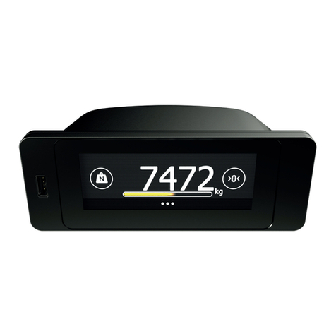
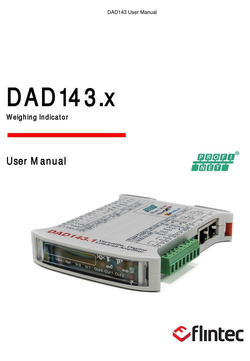
Flintec DAD143 Series User manual

DAD143 User Manual
DAD143.x
Weighing Indicator
User Manual

DAD 143.x User Manual - EtherCAT Rev. 1.0.1 November 2022 Page 2 of 87
Table of Contents
1Introduction .....................................................................................................................................................................6
1.1 Disclaimer .....................................................................................................................................................................................6
1.2 Safety Instructions .....................................................................................................................................................................7
2Specifications ..................................................................................................................................................................8
3.......................................................................................................9
3.1 Housing & Terminals..................................................................................................................................................................9
3.2 Terminals Load Cell Connection.............................................................................................................................................9
3.3 Load Cell Connection.................................................................................................................................................................9
3.4 Terminals Power Supply.........................................................................................................................................................10
3.5 Terminals Service Port RS 232..............................................................................................................................................10
3.6 Ethernet Based Ports...............................................................................................................................................................10
3.7 LED Indicators Terminal 27 .................................................................................................................................................11
3.8 Seal Switch...................................................................................................................................................................................11
3.9 Logic Inputs & Outputs............................................................................................................................................................12
3.10 Analog Outputs ........................................................................................................................................................................12
4Communications and Getting started ....................................................................................................................13
4.1 Service Port ................................................................................................................................................................................13
4.2 Command Language ...............................................................................................................................................................13
4.3 Baud Rate....................................................................................................................................................................................13
4.4 Getting Started via service port RS 232.............................................................................................................................13
4.5 Getting Started Via Ethernet based Port, e.g. protocol for EtherNet/IP..................................................................14
4.6 Downloading and Installing Npcap Free Edition .............................................................................................................14
5Menu Structure For Keybord Setup / Inspection ............................................................................................... 16
6Setup via Front Panel Keyboard...............................................................................................................................17
6.1 Keyboard Buttons.....................................................................................................................................................................17
6.2 Use of Keyboard Buttons .......................................................................................................................................................17
6.3 Menu 1 System Zero.............................................................................................................................................................18
6.4 Menu 2 System Span ...........................................................................................................................................................19
6.5 Menu 3 Display .....................................................................................................................................................................20
6.6 Menu 4 Filter & Motion Detection....................................................................................................................................21
6.7 Menu 5 Analog Output....................................................................................................................................................... 22
6.8 Menu 6 Logic Inputs............................................................................................................................................................ 23
6.9 Menu 7 Logic Outputs.........................................................................................................................................................24
6.10 Menu 8 Data Communication..........................................................................................................................................25
6.11 Factory Default via Front Panel ...........................................................................................................................................27
6.12 Error Codes - shown in the Front Panel Display .............................................................................................................27
7Examples of calibration .............................................................................................................................................28
7.1 Example 1 Calibration procedure using weights.........................................................................................................28
7.2 Example 2 ...................................................................30

DAD 143.x User Manual - EtherCAT Rev. 1.0.1 November 2022 Page 3 of 87
8Setup via PC / PLC - Command Overview -.........................................................................................................32
8.1 Special Commands of DAD143.x Overview..................................................................................................................35
8.2 AT Auto Transmit (only for RS 232 connection)...........................................................................................................35
8.3 AT Auto Transmit (only for PLC connection).................................................................................................................35
8.3.1 LE Last Error (command using only for RS 232 connection)..............................................................................................36
9Setup via PC / PLC - Command Descriptions......................................................................................................37
9.1 System Diagnosis Commands ID, IH, IV, IS, SR, RS.................................................................................................... 37
9.1.1 ID Get Device Identity........................................................................................................................................................................37
9.1.2 IV Get Firmware Version................................................................................................................................................................... 37
9.1.3 IS Get Device Status ...........................................................................................................................................................................37
9.1.4 SR Reset Firmware DAD143.x.........................................................................................................................................................38
9.1.5 RS Read Serial Number .....................................................................................................................................................................38
9.2 Calibration Commands ..............38
9.2.1 CE Read TAC* Counter / Open Calibration Sequence.............................................................................................................38
9.2.2 .......................................................................................................................................39
9.2.3 CI Set Minimum Output Value................................................................................................................................................39
9.2.4 MR Set Multi-range / Multi-interval.....................................................................................................................................39
9.2.5 DS Set Display Step Size...........................................................................................................................................................40
9.2.6 DP Set Decimal Point Position..................................................................................................................................................40
9.2.7 CZ Set Calibration Zero Point....................................................................................................................................................40
9.2.8 CG Set Calibration Gain (Span)................................................................................................................................................40
9.2.9 CV Calibrate Value ......................................................................................................................................................................40
9.2.10 AV Show Actual Internal mV/V Value....................................................................................................................................41
9.2.11 ZT Zero Tracking............................................................................................................................................................................41
9.2.12 FD Reset to Factory Default Settings.......................................................................................................................................41
9.2.13 ZR Zero Range..................................................................................................................................................................................41
9.2.14 ZI Initial Zero ON / OFF................................................................................................................................................................41
9.2.15 TM Tare mode...............................................................................................................................................................................42
9.2.16 TN Set / Clear Non-Volatile Tare............................................................................................................................................42
9.2.17 ZN Set / Clear Non-Volatile Zero ...........................................................................................................................................42
9.2.18 ZM Zero Mode...............................................................................................................................................................................42
9.2.19 AZ Absolute zero point calibration (eCal)............................................................................................................................42
9.2.20 AG Absolute gain calibration (eCal)........................................................................................................................................43
9.2.21 CS Save the Calibration Data......................................................................................................................................................43
9.2.22 SU Save User Setup in EEPROM.............................................................................................................................................43
9.2.23 RU Restore User Setup to DAD143.x......................................................................................................................................43
9.2.24 FT Firmware Type........................................................................................................................................................................43
9.3 Motion Detection Commands NR, NT............................................................................................................................44
9.3.1 - ..............................................................................................................................................................44
9.3.2 - ...............................................................................................................................................44
9.4 Filter Setting Commands FM, FL, PF, UR ......................................................................................................................44
9.4.1 FM Filter Mode...................................................................................................................................................................................44
9.4.2 FL Filter Settings...........................................................................................................................................................................45
9.4.3 PF Pre-filter....................................................................................................................................................................................47
9.4.4 UR Update Rate and Averaging...............................................................................................................................................47
9.5 Taring and Zeroing Commands SZ, RZ, ZN, ST, RT, SP, TN, RW, TI.......................................................................47
9.5.1 SZ Set System Zero..........................................................................................................................................................................47
9.5.2 RZ Reset Zero................................................................................................................................................................................47
9.5.3 ST Set Tare......................................................................................................................................................................................48
9.5.4 RT Reset Tare.................................................................................................................................................................................48
9.5.5 SP Set Preset Tare..........................................................................................................................................................................48
9.5.6 TW Window for Automatic Taring........................................................................................................................................48
9.5.7 TI Averaging Time for Automatic Taring................................................................................................................................49
9.6 Output Commands GG, GN, ON, GT, GS, GW, GA, GH, GM, RM, GO, GV..............................................................49
9.6.1 GG Get Gross Value ..........................................................................................................................................................................49
9.6.2 GN Get Net Value..........................................................................................................................................................................49
9.6.3 GT Get Tare Value.......................................................................................................................................................................49

DAD 143.x User Manual - EtherCAT Rev. 1.0.1 November 2022 Page 4 of 87
9.6.4 GS Get ADC Sample Value........................................................................................................................................................49
9.6.5 .......................................................................................................................49
9.6.6 OF Output Format for Data String GW................................................................................................................................50
9.6.7 GA Get Triggered Average Value............................................................................................................................................50
9.6.8 GH Get Hold Value...........................................................................................................................................................................51
9.6.9 TH Trigger Hold Value..................................................................................................................................................................51
9.6.10 GM Get Peak Value.......................................................................................................................................................................51
9.6.11 RM Reset of Peak Value..............................................................................................................................................................51
9.6.12 GO Get Peak To Peak Value.......................................................................................................................................................51
9.6.13 GV Get Valley Value.....................................................................................................................................................................51
9.7 Auto-Transmit Commands SG, SN, SW, SA, SH, SM, SO, SV....................................................................................51
9.7.1 SG Send Gross Value continuously................................................................................................................................................52
9.7.2 SN Send Net Value continuously...............................................................................................................................................52
9.7.3 ..........................................................................................52
9.7.4 SA Send Triggered Average Value automatically................................................................................................................52
9.7.5 SH Send Hold Value continuously.............................................................................................................................................52
9.7.6 SM Send Peak Value continuously...........................................................................................................................................52
9.7.7 SO Send Peak To Peak Value continuously.........................................................................................................................52
9.7.8 SV Send Valley Value continuously........................................................................................................................................52
9.8 Logic Input Functions & Status ........................................................................................................................53
9.8.1 ..............................................................................................................................................................................53
9.8.2 IN Read status of the logic inputs...........................................................................................................................................53
9.9 Logic Output Commands - .....................................................................................53
9.9.1 IO Read / Modify the Status of the logic Outputs..................................................................................................................53
9.9.2 OM Control of the logic outputs by the host application ...............................................................................................54
9.9.3 ............................................................................................................................................54
9.9.4 .......................................................................................................................................................................55
9.9.5 ...................................................................................................................55
9.9.6 .............................................................................................................................................................56
9.9.7 HT Hold time for all Setpoints....................................................................................................................................................56
9.10 Communication Setup Commands AD, BR, DX, OP, CL, TD....................................................................................56
9.10.1 AD Device Address.......................................................................................................................................................................56
9.10.2 BR Baud Rate.................................................................................................................................................................................56
9.10.3 DX Operation Mode Half-/Full-Duplex................................................................................................................................. 57
9.10.4 OP Open Device............................................................................................................................................................................57
9.10.5 CL Close Devices..........................................................................................................................................................................57
9.11 Analog Output AA, AH, AL, AM, AR (only in DAD 143.1)............................................................................................58
9.11.1 AA Analog Output Base............................................................................................................................................................58
9.11.2 AH Set Analog High Level..........................................................................................................................................................58
9.11.3 AL Set Analog Low Level..............................................................................................................................................................58
9.11.4 AM Set Analog Output Mode..................................................................................................................................................58
9.11.5 AR Set Analog Reference Value...............................................................................................................................................58
9.12 Save Calibration and Setup CS, WP, SS, AS, GI, PI......................................................................................................59
9.12.1 CS Save the Calibration Data......................................................................................................................................................59
9.12.2 WP Save the Setup Parameters..............................................................................................................................................59
9.12.3 SS Save Setpoint Parameters.....................................................................................................................................................59
9.12.4 AS Save Analog Output Parameters (only DAD 143.1).......................................................................................................59
9.12.5 GI Get an Image File from the EEPROM.................................................................................................................................59
9.12.6 PI Download an Image File to the EEPROM..........................................................................................................................60
9.13 Trigger Commands SD, MT, GA, TE, TR, TL, SA...........................................................................................................60
9.13.1 SD Start Delay Time....................................................................................................................................................................60
9.13.2 MT Measuring Time....................................................................................................................................................................60
9.13.3 GA Get Triggered Average Value............................................................................................................................................60
9.13.4 TE Trigger Edge..............................................................................................................................................................................61
9.13.5 TR Software Trigger.....................................................................................................................................................................61
9.13.6 TL Trigger Level..............................................................................................................................................................................61
9.13.7 SA Send Triggered Average Value automatically...............................................................................................................61
10 Legal For Trade Applications....................................................................................................................................62

DAD 143.x User Manual - EtherCAT Rev. 1.0.1 November 2022 Page 5 of 87
10.1 Access to metrological data and weighing range adjustment..................................................................................62
10.2 Protection of the metrological data and the scale calibration..................................................................................62
11 Calibration and Calibration Sequence....................................................................................................................63
12 Firmware Update Program...................................................................................................................................... 64
12.1 FU Firmware Update .............................................................................................................................................................64
12.2 FD Reset to Factory Default Settings................................................................................................................................65
12.3 Import / Export of the Device Settings via DOP 4 .....................................................................................................65
13 Service Commands Overview EtherCAT............................................................................................................66
13.1 General System Command PS, SR, WP .........................................................................................................................66
13.1.1 PS Protocol Select..........................................................................................................................................................................66
13.1.2 SR Software Reset ......................................................................................................................................................................66
13.1.3 WP Write Parameters.................................................................................................................................................................66
13.2 Ethernet Setup Commands AP and MA........................................................................................................................67
13.2.1 NA Network Address.....................................................................................................................................................................67
13.2.2 AP Address assign Protocol......................................................................................................................................................67
13.2.3 MA MAC Addresses....................................................................................................................................................................67
14 Cyclic Data Transfer - EtherCAT............................................................................................................................. 68
14.1 Data sent from the DAD 143.x to the PLC........................................................................................................................68
14.1.1 Data package sent from the DAD 143.x.................................................................................................................................68
14.1.2 CmdStatus........................................................................................................................................................................................68
14.1.3 CmdRdData......................................................................................................................................................................................69
14.1.4 Data1...................................................................................................................................................................................................69
14.1.5 Data2..................................................................................................................................................................................................69
14.1.6 Qualifier.............................................................................................................................................................................................69
14.1.7 IoData.................................................................................................................................................................................................69
14.1.8 DataType1.........................................................................................................................................................................................69
14.1.9 DataType2........................................................................................................................................................................................69
14.2 Data sent from the PLC to the DAD 143.x........................................................................................................................70
14.2.1 Data package sent to the DAD 143.x.......................................................................................................................................70
14.2.2 CmdWrData.....................................................................................................................................................................................70
14.2.3 Index...................................................................................................................................................................................................70
14.2.4 Subindex............................................................................................................................................................................................70
14.2.5 RW.......................................................................................................................................................................................................70
14.2.6 SendCmd...........................................................................................................................................................................................70
14.2.7 ShortCmd..........................................................................................................................................................................................70
14.2.8 Select1.................................................................................................................................................................................................71
14.2.9 Select2.................................................................................................................................................................................................71
15 Acyclic Data Transfer - EtherCAT ...........................................................................................................................72
15.1 Acyclic read example...............................................................................................................................................................72
16 Appendix A DAD 143.x ESI File..............................................................................................................................72
17 Appendix B SDO list for the DAD 143.x ..............................................................................................................73
18 Instructions for program ver. 1.3.0.0 or higher..............................................................80

DAD 143.x User Manual - EtherCAT Rev. 1.0.1 November 2022 Page 6 of 87
1Introduction
The all-in-one Digital Amplifier DAD 143.x is a universal device for any weighing, filling or dosing operations
and for force measurements with strain gage sensors. The DAD143 is designed for DIN (TS35) rail mount.
To grant the quality and allow legal weighing, the DAD143.x is OIML R76 approved (pending).
The DAD 143.x supports a number of industrial Ethernet based protocols for industrial weighing, control and
- -
Ethernet
for direct control of valves or bars etc.
The device can be controlled either by the front keys, via service port RS232 or 2 Ethernet based ports. The 2
logic inputs and 3 logic outputs make complex control functions easy. The 3 logic outputs can be controlled
external, too.
1.1 Disclaimer
All rights reserved.
No part of this publication may be reproduced, stored in a retrieval system, or transmitted in any form or by
any means, mechanical, photocopying, recording, or otherwise, without the prior written permission of
Flintec.
No patent liability is assumed with respect to the use of the information contained herein. While every
precaution has been taken in the preparation of this book, Flintec assumes no responsibility for errors or
omissions. Neither is any liability assumed for damages resulting from the use of the information contained
herein.
The information herein is believed to be both accurate and reliable. Flintec, however, would be obliged to be
informed if any errors occur. Flintec cannot accept any liability for direct or indirect damages resulting from
the use of this manual.
Flintec reserves the right to revise this manual and alter its content without notification at any time.
Neither Flintec nor its affiliates shall be liable to the purchaser of this product or third parties for damages,
losses, costs, or expenses incurred by purchaser or third parties as a result of: accident, misuse, or abuse of
this product or unauthorized modifications, repairs, or alterations to this product, or failure to strictly comply
with Flintec operating and maintenance instructions.
Flintec shall not be liable against any damages or problems arising from the use of any options or any
consumable products other than those designated as Original Flintec Products.
NOTICE: The contents of this manual are subject to change without notice.

DAD 143.x User Manual - EtherCAT Rev. 1.0.1 November 2022 Page 7 of 87
1.2 Safety Instructions
CAUTION: READ this manual BEFORE operating or servicing this equipment. FOLLOW
these instructions carefully. SAVE this manual for future reference. DO NOT allow
untrained personnel to operate, clean, inspect, maintain, service, or tamper with this
equipment. ALWAYS DISCONNECT this equipment from the power source before
cleaning or performing maintenance.
CALL Flintec for parts, information, and service.
WARNING: Only permit qualified personnel to service this equipment. Exercise care when
making checks, tests and adjustments that must be made with power on. Failing to
observe these precautions can result in bodily harm.
WARNING: For continued protection against shock hazard connect to properly grounded
outlet only. Do not remove the ground prong.
WARNING: Disconnect all power to this unit before removing the fuse or servicing.
WARNING: Before connecting/disconnecting any internal electronic components or
interconnecting wiring between electronic equipment always remove power and wait at
least thirty (30) seconds before any connections or disconnections are made. Failure to
observe these precautions could result in damage to or destruction of the equipment or
bodily harm.
CAUTION: Observe precautions for handling electrostatic sensitive devices.

DAD 143.x User Manual - EtherCAT Rev. 1.0.1 November 2022 Page 8 of 87
2Specifications
DAD 143.x Specifications
Accuracy class
III
Test certificate according OIML R76
EU Type approved for 10000 intervals
AD converter
Delta-Sigma, ± 24 bit
Analog input range
±15 mV bipolar (± 3 mV/V @ 5 VDC excitation)
Minimum input sensitivity
0.2 μV/e (legal for trade); 0.05 μV/d (non legal for trade)
Linearity
< 0.001 % FS
Temperature effect on zero
< ±4 ppm/°K (typical < ±2 ppm/°K)
Temperature effect on span
< ±8 ppm/°K (typical < ±4 ppm/°K)
Excitation
5 V DC, load cell(s) resistance 50 - 2000 ohms; 6 wire technic
Conversion rate
Max. 600 values/second, selectable in 8 steps
Resolution external
± 600 000 counts @ ± 3 mV/V input signal
CALIBRATION & WEIGHING FUNCTIONS
Calibration
Electronical calibration in mV/V (eCal) or with test weight(s)
Digital low pass filter
FIR Filter 2.5 to 19.7 Hz or IIR Filter 0.25 to 18 Hz - adjustable in 8 steps
Weighing functions
Zero, gros, tare, net, filter, etc.
Application modes
None automatic weighing instrument (NAWI) or triggered measurement
Communication & Setup
Communication ports
RS232 and Ethernet
Setup & Calibration
via front p
Display
spectral filter 565 nm for improved contrast
Keyboard
4 pcs, Ø 3mm robust, for setup / calibration, zero, tare
Power supply
10 ... 30 VDC, < 4.0 W @ 24 VDC
Environmental Conditions
Operating temperature
-15 °C to +55 °C at maximal 85% rh, non condensing
Storage temperature
-30 °C to +70 °C
Enclosure & protection
Plastic housing, for DIN rail mount (TS35) , protection IP40
Dimensions and weight
120 x 102 x 23 mm (L x H x W), weight approx. 170 g
Vibration resistance
2.5g @ operation, 5g @ storage
Service Port
RS 232, 9600 ... 460800 Baud half/full duplex
Protocol & Address range
ASCII; address range 255
Ethernet Ports (2 pcs.)
RJ45, 10/100 Mbit/s, integrated 2 port switch, isolated
Duplex modes
Half Duplex, Full Duplex, Auto-Negotiation
MDI modes
MDI, MDI-X, Auto-MDIX
Data transport layer
Ethernet II, IEEE 802.3
Analog current output
0 20mA or 4 20mA, 500ohm, isolated or
Analog voltage output
0 10V, 0 5V, ±5V, ±10V, 10kohm, isolated
Digital logic inputs
2 inputs (10 30V, 1 3mA), commond ground, isolated
Digital logic outputs
3outputs (semiconductor relais) 30 V DC/AC, 0.5 A,
common ground, isolated

DAD 143.x User Manual - EtherCAT Rev. 1.0.1 November 2022 Page 9 of 87
3Hardware, Wiring and
3.1 Housing & Terminals
3.2 Terminals Load Cell Connection
Colour code of e.g. standard load cells
3.3 Load Cell Connection
The load cell wiring should be made carefully before energizing to avoid damages to the amplifier and the
load cells. The input resistance of the load cells that you want to connect should be 50 Ω(ohms).
In case of using a load cell / scale with 4 wire cable, you have to short-circuit (bridge) the pins 1 & 2 and 6 & 7.
Remark:
-wire cable of a load cell, as the cable is part of the factory calibration
(signal & temperature compensation).
DAD 143.x
Load cell
input
Function
Pin no.
1
+ Exc
+ Excitation for load cell
2
+ Sen
+ Sense for load cell
3
+ Inp
+ Signal of load cell
4
Shld.
Shield load cell
5
–Inp
–Signal of load cell
6
–Sen
–Sense for load cell
7
–Exc
–Excitation for load cell
Scale information for ‘legal for trade’ use
Terminals of the DAD 143.x

DAD 143.x User Manual - EtherCAT Rev. 1.0.1 November 2022 Page 10 of 87
3.4 Terminals Power Supply
Depending on the grounding concept of the plant/scale, terminal 20 or 21 has to be connected to terminal 22.
Terminal 4 (shld load cell) and 22 (Ground chassis) are internal connected.
Note: The power supply must be able to support about 200mA per DAD 143.x.
3.5 Terminals Service Port RS 232
The RS 232 port can be used for communication with a PC or PLC system.
3.6 Ethernet Based Ports
Please Note
: s the protocol Ethernet TCP/IP !!!
DAD 143.x
RS 232
Function
Terminal no.
23
TxD
Transmit Data
24
RxD
Receive Data
25
GND
Signal ground RS 232
The two RJ45 Ethernet ports (28 & 29) are connected to an
internal switch. The Ethernet ports support 10BASE-T and
100BASE-TX. Half-, Full- and auto negotiated duplex mode.
MDI, MDI-X and Auto-MDIX crossover control.
Pin
Signal
Description
1
Tx+
Transmit data positive
2
Tx-
Transmit data negative
3
Rx+
Receive data positive
4
Term 1
Connected and terminated to
“Shld” via RC combination *
5
Term 1
6
Rx-
Receive data negative
7
Term 2
Connected and terminated to
“Shld” via RC combination *
8
Term 2
*Bob Smith termination
DAD 143.x
Power in
Function
Pin no.
18
+
Power supply +12..24 V DC
19
+
Power supply +12..24 V DC
20
-
Common ground / 0 V DC
21
-
Common ground / 0 V DC
22
Shld.
Chassis ground

DAD 143.x User Manual - EtherCAT Rev. 1.0.1 November 2022 Page 11 of 87
3.7 LED Indicators Terminal 27
LED
Colour
State
Description
Sys
On
Protocol firmware running
On or flashing
Service / maintenance firmware running in various
modes
RN
RUN
On
Connected at least one TCP connection is
established.
Flashing, 1Hz
Ready but not configured
Flashing, 5Hz
Configured and ready for communication
Off
Not ready
ER
ERR
Off
No errors
Flashing, 2Hz
System error
On
Communication error
Lnk1
On or flashing
Port 1 Ethernet link established
Act1
Flashing
Port 1 Ethernet Rx/Tx activity
Lnk2
On or flashing
Port 2 Ethernet link established
Act2
Flashing
Port 2 Ethernet Rx/Tx activity
Table of LED indicators for Modbus TCP protocol
3.8 Seal Switch
Traceable Access Code (TAC) protected calibration commands
In case the seal switch (pins 26) is open, the following commands or menus be proceeded:
- Calibration Zero
- Calibration Gain
- Calibration Absolute Zero
- Calibration Absolute Gain
- Calibration Minimum
- Calibration Maximum
- Zero Tracking
- Zero Range
- Display Step Size
- Decimal Point
- Calibration Save
- Factory Default
- Non Volatile Tare
- Non Volatile Zero
- Initial Zero @ power ON, etc.
Activity Link of Port 1/2
Setup or changes of calibration can only be performed with an
open seal switch (26). Changes lead to get a new TAC value,
increased by +1.
Running a legal for trade application needs the jumper
connected to the switch pins and a seal. A broken seal shows
up changes of calibration, which are not allowed.
Protected commands see below.

DAD 143.x User Manual - EtherCAT Rev. 1.0.1 November 2022 Page 12 of 87
3.9 Logic Inputs & Outputs
The 2 inputs can e.g. get the function to act as the ZERO or TARE button, see chapter 8.10.
The 3 outputs act as switches for setpoints with hysteresis, switch behavior etc. Several reference values such
as net weight, peak weight or average can be used, see chapter 8.11.
3.10 Analog Outputs
The DAD143.1 offers 2 isolated analog outputs for current
and voltage. For your application you can choose one of the
six modes like:
➢4 to 20mA / 0 to 20mA
➢0 to +5V / 0 to +10V
➢-5 to +5V / -10 to +10V.
Note
: The DAD143.2 has no analog outputs.
DAD143.x
Logic In- /
Output
Function
Pin no.
8
0
‘High’: +12 ... +24VDC
9
1
‘High’: +12...+24VDC
10
C
‘Low’ Common 0/1: 0V
11
0
Logic output 0
12
1
Logic output 1
13
2
Logic output 2
14
C
Common 0/1/2:
12 ... 24V oder 0V
DAD143.1
Analog
Outputs
Function
Pin no.
15
0 Com
Signal ground analog output
16
+/- Vout
Voltage output
17
Iout
Current output
Note Logic Inputs:
The pulse duration must be at least 50ms.
Note Logic Outputs:
The connection C can be used for either
‘high’ level (24V AC/ DC) or ‘low’ level (0V).

DAD 143.x User Manual - EtherCAT Rev. 1.0.1 November 2022 Page 13 of 87
4Communications and Getting started
4.1 Service Port
Communicating with the digital device DAD 143.x is carried out via serial service port RS 232.
The data format is the familiar 8/N/1 structure (8 data bits, no parity, 1 stop bit).
Available baud rates of RS 232 port are as follows: 9600, 19200, 38400, 57600, 115200, 230400 and
460800 baud.
Factory default: 115200 baud
4.2 Command Language
The command set of the DAD 143.x is based on a simple ASCII format (2 letters). This enables the user to setup
the device, get results or check parameters.
Example: DAD 143.x is connected via the RS 232 port to a PC / PLC system. You want to get the identity,
firmware version or net weight.
Remark:
(LF) is not required and will be ignored by the device, if neccessary.
Master (PC / SPS) sends
Slave (DAD 143.x) responds
Meaning
ID
D:1430
identity of the active device
IV
V:0140
Firmware version of the active device
GN
N+123.45
Net weight with algebraic sign; decimal
point is fixed as setup with command DP
4.3 Baud Rate
For baud rate setup use the command BR, see chapter 9.10.2.
4.4 Getting Started via service port RS 232
You will require:
•PC or PLC with a RS 232 communication port
•A load cell / scale with test weights or a load cell simulator
•A 12 to 24 VDC power supply capable of delivering approximately 200mA for each DAD 143.x
incl. the connected load cell(s).
•One or more DAD 143.x.
•A suitable ASCII communication software. **
Refer to the wiring diagrams in chapter 3.
**
You can easily communicate between a PC and a DAD 143.x using programs such as Procomm, Telemate,
Kermit, HyperTerminal or HTerm etc.
Additionally, the very powerful software DOP 4 (ver. 2.4.1.0 or higher) with graphical user interface and
oscilloscope function for the operating systems Windows XP/Vista/7/8/10 is available.
Hint:
A download of a new firmware version can be done with the program Protocol Firmware Loader PFL
ver. 1.00 or higher. The download has to be done via service port RS232 at a fixed baud rate of 115200.
More details of this procedure see chapter 12.

DAD 143.x User Manual - EtherCAT Rev. 1.0.1 November 2022 Page 14 of 87
4.5 Getting Started Via Ethernet based Port, e.g. protocol for
EtherNet/IP
Following steps outlined below simplify the process of setting up a system for the first time.
•Connect the DAD to a suitable power supply.
•Connect a Windows PC to the DAD 143.x service port through a RS232 COM port or an USB to RS232
converter.
•A terminal program e.g. HyperTerm can be used for verifying or changing the setup of the DAD 143.x.
Default service port settings are: 115200 baud, 8 data bits, No parity and one stop bit.
•Or simply use the service commands for DAD 143.x of the EtherCAT Viewer, see below.
Screenshot of the EtherCAT Viewer ver. 1.2.0.0 Service Commands.
•Here you can edit the service parameters to the application needs.
•
•Connect one of the DAD Ethernet ports to your PC / PLC. The DAD 143.x needs for EtherCAT no
IP address. The DAD143.x has an Identification Value, e.g. 73 as shown above.
•To run the EtherCAT Viewer, you need to install on your PC a Npcap driver for your OS. You can find
•A Windows demo program for testing the EtherCAT functionality can be downloaded from
www.flintec.com
See screenshot of EtherCAT Viewer version 1.2.0.0 or higher on next page.
4.6 Downloading and Installing Npcap Free Edition
If you want to test the EtherCAT Viewer on your computer, you find support via the following link:
https://nmap.org/npcap/
You have to choose the required Installer for your OS.

DAD 143.x User Manual - EtherCAT Rev. 1.0.1 November 2022 Page 15 of 87
Screenshot of the EtherCAT Viewer 1.2.0.0
•
•Press the butto -
Index, Current Value etc. per command.
For starting with another Ethernet based communication, the procedure is similar.
For detailed technical information of the different PLC bus systems, please see individual manuals for
#Profinet IO or #Ethernet/IP or #EtherCAT or #Modbus TCP.

DAD 143.x User Manual - EtherCAT Rev. 1.0.1 November 2022 Page 16 of 87
5Menu Structure For Keybord Setup / Inspection
Table for protocol EtherCAT

DAD 143.x User Manual - EtherCAT Rev. 1.0.1 November 2022 Page 17 of 87
6Setup via Front Panel Keyboard
6.1 Keyboard Buttons
This is the ZERO button. This button can be used for zeroing in scale status
This is the TARE button. This button can be used for taring the scale in status
The two UP/DOWN buttons will be used for setup via the menu.
6.2 Use of Keyboard Buttons
Press the UP or DOWN button for more than 3 seconds to enter the setup menu of front
panel.
In setup menu use these buttons to select one of the menus 1 to 8 and make your selection in
the sub-menus or to setup single characters of the display.
Remark:
To enable calibration menu 1, 2 and 3 you have to remove the jumper
of seal switch (28). The TAC counter will increase by one after changes.
Enter in menu X to the different sub-menus of X. After choosing the setting with the UP or
DOWN button, use this key again for storing. This is the ENTER button
To leave menu X or sub-menu of X.
Leave with: press 1x TARE button for back to menu X.1 1st level or press 2x TARE button for
back to menu X
Menu 7.0.1.1 –Setup
Value 001000
X
Menu X
Select with UP / DOWN buttons
X
Enter with ZERO button
X
Leave with TARE button
X.1
Menu X - 1st level
Enter with ZERO button
X
Select with UP / DOWN buttons
Back with ZERO button
Leave with TARE button
X.1.1
Menu X - 2nd level
Enter with ZERO button
Select with UP / DOWN buttons
Enter with ZERO button
Leave with TARE button
X.1.1.1
Menu X - 3rd level
Enter with ZERO button
X
Select with UP / DOWN buttons
X
Enter with ZERO button
X
Use UP / DOWN buttons for single characters
0 0 1 0 0 0
Use TARE button for next number
x x x x x x
Back with ZERO button
X
Leave with: 1x TARE button back to menu X.1
2x TARE button back to menu X
X

DAD 143.x User Manual - EtherCAT Rev. 1.0.1 November 2022 Page 18 of 87
6.3 Menu 1 System Zero
Remark: Activate a new calibration with 1x Power OFF & ON !
1.
ZERO setup (Menu 1.1 to 1.4) TAC protected see chapter 9.2.1
1.1
Automatic Zero Tracking - Enable / Disable (command ZT)
-
Setting range
Disabled @ 00000, no ZERO Tracking
Enabled @ 00001 or higher (max 00255)
-
Setting 00001 sets a zero tracking range of ±0.5d
-
Setting 00002 up to 00255 sets a zero track range of
±1d up to ±127.5d, independent of decimal point setting
1.2
Calibrate system ZERO - gravimetric by weight / load (command CZ)
-
Display shows the actual input signal in mV/V. Press
ENTER button to store ZERO.
Remark: Scale should/must be unloaded.
1.3
Calibrate system ZERO - electronic by mV/V value (command AZ)
-
Use the UP/DOWN & MOVE RIGHT keys to setup the mV/V value at
which the device should read ZERO
1.4
System ZERO & TARE function
1.4.1
Store TARE value non volatile: ON / OFF (command TN)
-
ON: store non-volatile @ power OFF
-
OFF: delete @ power OFF
1.4.2
Store ZERO value non volatile: ON / OFF (command ZN)
-
ON: store non-volatile @ power OFF
-
OFF: delete @ power OFF
1.4.3
Initial ZERO @ power ON: ON / OFF (command ZI)
-
ON: proceed initial Zero @ power ON
-
Range is ±10% of Max (CM1 or CM2 or CM3)
1.4.4
ZERO range (increments) (command ZR)
-
-
-
Set the zero setting range in divisions.
The setting is independent of decimal point setting.
Disabled @ 00000, no ZEROing possible
Enabled @ 00001 or higher (max 999999)
In a legal for trade application, the standard value is ±2 % of Max.
The setup for a scale with 3 000e is i.e.:
- Max (CM) = 1 500 kg
- Step Size (SZ) = 0.5 kg
- Zero Range (ZR) of ±2 % = ± 30 kg, which is ± 60 d.

DAD 143.x User Manual - EtherCAT Rev. 1.0.1 November 2022 Page 19 of 87
6.4 Menu 2 System Span
Remark: Activate a new calibration with 1x Power OFF & ON !
2.
SPAN setup (Menu 2.1 to 2.4) TAC protected see chapter 10.2.1
2.1
Set SPAN Calibration value (command CG)
-
Set display value equivalent to calibration weight or to mV/V value derived
from load cell(s) test data.
2.2
Calibrate system SPAN - gravimetric by weight / load
-
Display shows the actual input signal in mV/V.
-
Apply test weight equivalent to calibration value (2.1).
-
Press ENTER button to store new SPAN signal.
2.3
Calibrate system SPAN - electronic by mV/V input (command AG)
-
Use the UP/DOWN & MOVE RIGHT keys to setup the mV/V value at which the
device should read SPAN.
-
Press ENTER button to store new SPAN signal.
2.4
Display the input signal in mV/V
-
This function displays the actual input signal of the load cell(s).
2.5
Display the firmware version, e.g. 1.47 (command IV)
-
Read and display the firmware version.
2.6
Display the actual TAC value, e.g. 34 (command CE)
-
Read and display the TAC value of the actual calibration.

DAD 143.x User Manual - EtherCAT Rev. 1.0.1 November 2022 Page 20 of 87
6.5 Menu 3 Display Remark: Activate a new calibration with 1x Power OFF & ON !
3.
Display setup (Menu 3.1 to 3.4) TAC protected see chapter 10.2.1
3.1
Display limits - Overrange / Underrange (commands CMn/CI)
3.1.o1
Display overrange limit CM1 (maximum value +999999) (CM1)
Use the UP/DOWN & MOVE RIGHT keys to setup the maximum display
value, above which the display shows over range (all dashes in the top
of the display).
3.1.o2
Display overrange limit CM2 (maximum value +999999) (CM2)
3.1.o3
Display overrange limit CM3 (maximum value +999999) (CM3)
3.1.U
Display underrange limit (minimum value -999999) (CI)
Use the UP/DOWN & MOVE RIGHT keys to setup the minimum display
value, above which the display shows under range (all dashes in the
bottom of the display).
3.2
Display step size - in digits [d] (command DS)
-
choose one out of 1, 2, 5, 10, 20, 50, 100, 200, 500
3.3
Decimal point position on the display (command DP)
-
choose one out of 0, 0.0, 0.00, 0.000, 0.0000, 0.00000
3.4
Setup of Multi-interval or Multi-range (command MR)
-
Choose 0 for Multi-interval or 1 for Multi-range scale.
Other manuals for DAD143 Series
1
This manual suits for next models
1
Table of contents
Other Flintec Measuring Instrument manuals
Popular Measuring Instrument manuals by other brands

ipf electronic
ipf electronic PT169070 instruction manual

Dewetron
Dewetron DEWE-30-32 Technical reference manual

Endress+Hauser
Endress+Hauser Micropilot S FMR540 operating instructions
Monroe Electronics
Monroe Electronics 268A-1 Operator's manual

Texmate
Texmate DI-60AE manual
Super Systems
Super Systems DP 2000 Operation manual
