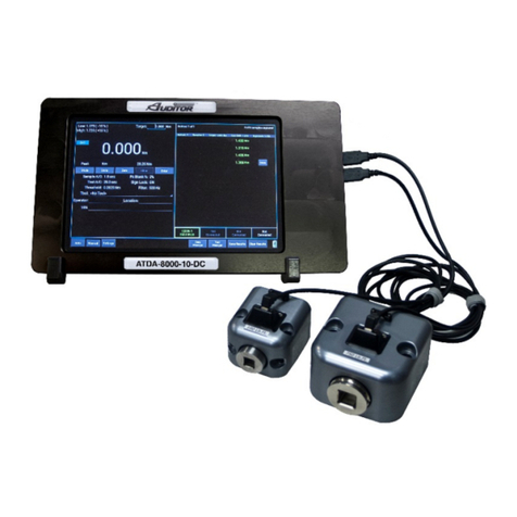
Aimco Auditor ATDA-DC User manual

ATDA-DC
Torque Data Analyzer/Collector
User Guide

2
CONTENTS
Safety Requirements...................................................................................................................................................3
Descriptions and Specifications
Screen and button Diagram.............................................................................................................................................. 4
Back Panel Diagram ........................................................................................................................................................ 5
Unit Specifications………………………………. .......................................................................................................... 5
Operating Instructions
Charging the ATDA......................................................................................................................................................... 6
Basic Navigation.............................................................................................................................................................. 6
Turning On / Off .............................................................................................................................................................. 6
Transducers
Connecting Transducers (TXDR) .................................................................................................................................... 7
Confirming TXDR Connection..................................................................................................................................... 7-8
Basic Functions
Operating Mode ............................................................................................................................................................... 8
Selecting Operating Mode ............................................................................................................................................... 8
Setting Engineering Units ................................................................................................................................................ 8
Run Mode
Using the ATDA in Run Mode ........................................................................................................................................ 9
Accessing Run Mode ....................................................................................................................................................... 9
Measure Mode
Using the ATDA in Measure Mode ................................................................................................................................. 9
Accessing Memory Mode................................................................................................................................................ 9
Storing Rundown Torque Values..................................................................................................................................... 9
Reviewing Rundown Torque Values ............................................................................................................................... 9
Reviewing Statistical Information.................................................................................................................................. 10
ATDA Menu Functions
Accessing Menu Functions ............................................................................................................................................ 11
Peak Options Menu
Accessing the Peak Options Menu................................................................................................................................. 12
Auto Clear...................................................................................................................................................................... 12
Setting Auto Clear.......................................................................................................................................................... 13
Clearing a Torque Value / Run Mode ............................................................................................................................ 13
Clear / Enter Torque Value / Measure Mode ................................................................................................................. 13
Clearing Previous Torque Values .................................................................................................................................. 13
Filter............................................................................................................................................................................... 13
Setting the Filter Value .................................................................................................................................................. 14
Peak Blanking................................................................................................................................................................ 14
Setting the Peak Blanking Value.................................................................................................................................... 14
Sign Lock....................................................................................................................................................................... 14
Turning Sign Lock On/Off............................................................................................................................................. 14
Resetting Sign Lock....................................................................................................................................................... 14
Edit Limits ..................................................................................................................................................................... 15
Setting High and Low limits .......................................................................................................................................... 15
System Menu
Accessing the System Menu .......................................................................................................................................... 16
Sleep .............................................................................................................................................................................. 16
Setting the Sleep Timer.................................................................................................................................................. 16
Lockout Menu................................................................................................................................................................ 16
Setting the Lockout Modes ............................................................................................................................................ 16
Contrast.......................................................................................................................................................................... 17
Information / Accessing the Information System........................................................................................................... 17
Data Menu
Accessing the Data Menu .............................................................................................................................................. 17
Print Data Requirements ................................................................................................................................................ 17
RS232 Transfer Protocol................................................................................................................................................ 17
Data Stream Format ....................................................................................................................................................... 18
Pinout Diagram .............................................................................................................................................................. 18
Print Memory / Print Memory w/SPC / Clear Memory / Reset All................................................................................ 18

3
Audit Menu
User Name / Link to PC / Procedure to Launch ............................................................................................................. 19
Tools Manager / Jobs Manager...................................................................................................................................... 20
SAFETY REQUIREMENTS
SAVE THESE INSTRUCTIONS
1) WORK AREA
a) Keep work area clean and well lit. Cluttered and dark areas invite accidents.
b) Do not operate power tools in explosive atmospheres, such as the presence of flammable
liquids, gases or dust. Power tools create sparks which may ignite the dust or fumes.
c) Keep children and bystanders away while operating a power tool. Distractions can cause you to
lose control.
2) ELECTRICAL SAFETY
a) Power too plugs must match the outlet. Never modify the plug in any way. Do not use any
adapter plugs with earthed (grounded) power tools. Unmodified plugs and matching outlets will
reduce risk of electric shock.
b) Avoid body contact with earthed or grounded surfaces such a s pipes, radiators, ranges and
refrigerators. There is an increased risk of electric shock if your body is earthed or grounded.
c) Do not expose power tools to rain or wet conditions. Water entering a power tool will increase the
risk of electric shock.
d) Do not abuse the cord. Never use the cord for carrying, pulling or unplugging the power tool.
Keep cord away from heat, oil, sharp edges or moving parts. Damaged or entangled cords
increase the risk of electric shock.
e) When operating a power tool outdoors, use an extension cord suitable for outdoor use. Use of a
cord suitable for outdoor use reduces the risk of electric shock.
3) PERSONAL SAFETY
a) Stay alert, watch what you are doing and use common sense when operating a power tool.
Do not use a power tool while you are tired or under the influence of drugs, alcohol or
medication. A moment of inattention while operating power tools may result in serious personal injury.
b) Use safety equipment. Always wear eye protection. Safety equipment such as dust mask, non-skid
safety shoes, hard hat, or hearing protection used for appropriate conditions will reduce personal
injuries.
c) Avoid accidental starting. Ensure the switch is in the off-position before plugging in. Carrying
power tools with your finger on the switch or plugging in power tools that have the switch on invites
accidents.
d) Remove any adjusting key or wrench before turning the power tool on. A wrench or a key left
attached to a rotating part of the power tool may result in personal injury.
e) Do not overreach. Keep proper footing and balance at all times. This enables better control of the
power tool in unexpected situations.
f) Dress properly. Do no wear loose clothing or jewelry. Keep your hair, clothing and gloves away
from moving parts. Loose clothes, jewelry or long hair can be caught in moving parts.
g) If devices are provided for the connection of dust extraction and collection facilities, ensure
these are connected and properly used. Use of these devices can reduce dust-related hazards.
4) POWER TOOL USE AND CARE
a) Do not force the power tool. Use the correct power tool for your application. The correct power
tool will do the job better and safer at the rate for which it was designed.
b) Do not use the power tool if the switch does not turn it on and off. Any power tool that cannot be
controlled with the switch is dangerous and must be repaired.

4
SCREEN AND BUTTON DIAGRAM
Figure 1
1.
Data Display
12.
Right Selection Button
2.
Operating Mode
Data Storage Mode
3.
Menu Mode Status
Increase Parameter Value
4.
Selection Arrow – Down
Select Parameter
Change Operating Mode
13.
Selection Arrow - Up
Scroll Down through Menu screens
Change Engineering Units
5.
Left Selection Button
Scroll Up through parameter screens
Menu Mode
14.
Data Storage Mode Status
Reduce Parameter Value
15.
Engineering Unit Status
Select Parameter
16.
All Clear Status Indicator (Absent when A/C turned OFF
6.
NOK Value Indicator LED (RED)
17.
Menu Screen Indicator / Stored Rundown Number
7.
Clear Data Display Value / Manually ZERO Display
18.
Angle / Pulse Value Display
8.
Power On
19.
External Power Supply Indicator
9.
Power Off / Charging Mode
20.
Cursor Arrows
10.
Enter
21.
Audit Button
Set Values
Enter Audit/data collector menu
Back up one Menu Screen
22.
Zero Button
11.
OK Rundown / Charging Mode Ind LED (GREEN)
23.
Menu Button
1
17
15
14
10
12
13
16
4
5
7
3
2
19
18
9
6
11
8
20
21
22
23

5
Enables Link to PC / enters data collector menu
Figure 2
UNIT SPECIFICATIONS
Dimensions Width: 6.25”, Height: 4.25”, Depth: 1”
Weight 1 Lb
Power Requirements Main power 100-240VAC, 50-60hz from supplied charger,
or internal NiMH battery pack
Operating Temperature Range 0oto 50oC
Data Communication RS-232-C
Accuracy .5% +/- of indicated reading for top 90% of transducer full scale
Top of Unit
(orientation of connectors may be slightly different than illustration)

6
OPERATING INSTRUCTIONS
Charging the Auditor Torque Data Analyzer (ATDA)
1. Plug the 100 – 240 VAC Charger into DC Power Supply port (Figure 2)
2. Plug the Charger into a 100 – 240 VAC power outlet using the appropriate plug end.
3. Press the Off / Charge button on the front panel (Figure 1)
4. The Charging Mode Indicator LED should begin to flash green.
symbol will be displayed on the Main Display screen when the unit is on and plugged in to AC
power.
5. When the ATDA is fully charged the LED will stop flashing
6. The ATDA can be used as normal in AC mode with the charger connected.
7. When the Auditor internal battery is close to requiring a recharge, the symbol will show on the
Main Display screen. Recharge time is approximately 4-5 hours and can be done while the unit is in
use and on AC power.
Basic Navigation and Use of the Keypad
Many functions of the Auditor ATDA can be accessed by using the button directly below the
associated text on the display screen. For example, if the following screen were displayed:
the LEFT SELECTION BUTTON, which is directly below the MENU text field, would allow the
user to access the MENU features.
At anytime during use, pressing the ENTER button (Figure 1) will allow the user to back up by one screen. Pressing
the ENTER button enough times will always take the user back to the main display screen.
To enter the data collection mode press the AUDIT button, the unit will
prompt you for USER NAME, press soft button immediately under the
Done text when finished. The unit will list all available tools (files) for
testing. Use the scroll buttons to select tool/file.
Pressing the CLR button will return you to the RUN or sequential MEM
mode of the ATDA tester.
Turning On / Off
To turn the ATDA on, press the “ON”button (Figure 1)
The AIMCO logo will be displayed for approximately 4 seconds then the
unit will start at the RUN or sequential MEM mode of the tester.
To turn the ATDA off, simply press the “OFF”button.

7
TRANSDUCERS
The ATDA can be used with a variety of external transducers, whether supplied by AIMCO or another manufacturer.
Because manufacturers use a wide range of transducer technologies and connector types, verify that the transducer
you plan to use is capable of being connected to and communicating with the ATDA. For assistance with this, please
contact your AIMCO Distributor or authorized AIMCO Sales Representative.
AIMCO’s lines of Auditor™ brushless and industry-standard transducers are manufactured with the proper
connector-style for easy use with the ATDA and will be used as the example in all following instructions.
Two (2) optional cables are available from AIMCO to connect Auditor™ brand transducers to the ATDA:
•Part # ATDBLIS Connects the ATDA to any Auditor™ ABRT- or ARTIS Torque/Angle series transducer
•Part # ATDBRIS Connects the ATDA to any Auditor™ ARTIS Torque Only series transducer
Contact your AIMCO Distributor or AIMCO authorized Sales Representative for information on ordering these cables.
Connecting a Transducer
Align the red dot on the transducer-cable connector with the red dot on the TRANSDCUER CABLE INPUT port
(Figure 2) and firmly press the connector into the port.
Setting up the Transducer to be used
The Auditor Torque Data Analyzer must be set to recognize the transducer connected to the instrument. Most
transducers can be made to allow the Auditor Torque Data Analyzer to self-recognize the transducer simply when a
connection is made. For assistance with this, please contact your AIMCO Distributor or authorized AIMCO Sales
Representative for a transducer upgrade quotation.
For the typical, Industry Standard (IS) type of transducer, the setup procedure is as follows:
1. Turn the ATDA On.
2. Within 3 seconds of pressing the ON button, press the LEFT SELECTION BUTTON (Figure 1) for CAL
3. Press ENT to SELECT UNITS. If a transducer has been previously setup, the data for that previous
setup will be shown.
4. Units of measure for use in setting up the transducer may be changed in this screen by pressing the UP
OR DOWN SELECTION ARROW to scroll through the available units. Pressing ENT will select the
displayed unit of measure for use in setup and then display the SELECT FULL SCALE screen.
5. To change the number displayed to match the transducer being setup, press the RIGHT SELECTION
BUTTON to EDIT the number.
6. The upper right corner of the screen will display the digit number that use of the UP or DOWN
SELECTION ARROWS will effect. The bottom left corner of the screen shows the increment of
adjustment that each press of the UP or DOWN SELECTION ARROWS changes the digit by.
7. Once the number displayed on the screen matches the transducer to be used, press ENT to confirm the
set value.
8. The next screen will display “(-) 0.000” and the A-D counts. Press and hold the RIGHT SELECTION
BUTTON to EDIT the mV/V rating of the transducer being setup. System defaults to 2.00000 which is
standard for all Auditor IS transducers. Press ENT if this value is correct for the transducer being
setup. It is important to be sure that the sign (+/-) shown on the A-D matches the direction of the
Cal mode. If in +Cal then the sign must be positive. If in –Cal then the sign must be -. Rotation
of the transducer shaft will facilitate a change from + to – should that be necessary.
9. Percentage of Full Scale is the next adjustment. Default is 100. Should it be desired to limit the
readable range of the transducer to be used, use the RIGHT SELECTION BUTTON and the UP or
DOWN arrows to change this value. Hit ENT once the desired value is displayed.
10. Press the DOWN SELECTION ARROW to set the –Cal. Confirm –Cal by hitting ENT.Repeat steps 8
& 9.
11. After mV/V and Full Scale have been entered, the display returns to the A-D count screen. Hit ENT
12. If the value is correct, press ENT and PGM will show on the screen.
13. Press the LEFT SELECTION BUTTON to Save the setting. The unit will power itself off and will hold
the set value until it is changed in the future or a different Intellect transducer is attached to the unit.

8
Confirming Transducer Connection (for unit with a previous setup)
1. Turn the ATDA On.
2. Press the LEFT SELECTION BUTTON (Figure 1) for MENU
3. Use the SELECTION ARROW buttons to scroll to SYSTEM MENU (2)
4. Press the RIGHT SELECTION BUTTON for SELECT
5. Use the SELECTION AROW buttons to scroll to INFORMATION (2-4)
The following screen will be displayed:
The values in the TD: line should match the full scale value of the connected transducer. For example, if an
ABRT-50S-100 transducer is connected, the text on the Auditor screen should read TD: 100 NM or the mathematical
equivalent, such as TD: 73.8 FtLb.
Transducer Calibration Schedule Information
With Intellect enabled transducers, the ATDA can display information regarding the connected transducer’s serial
number, type, previous calibration date and next due-date for calibration.
From the System Information screen (2-4), press the LEFT SELECTION BUTTON (TD) to access the
Transducer Information screen. The following screen will be displayed:
Pressing any key while this screen is displayed will return the user to the previous System Information screen.

9
BASIC FUNCTIONS
OPERATING MODE Descriptions
By selecting the proper Operating Mode the user can properly take torque readings from a variety of manual and
powered tools.
•PEAK
This mode will provide a display of the maximum torque value achieved by the tool during operation. This
mode is used for all continuous drive tools and click-type torque wrenches.
•1st PEAK
This mode will detect and display the “first peak” achieved by click wrenches and cam-over screwdrivers.
•PULSE
This mode will display the maximum torque value achieved by discontinuous drive tools such as pulse tools
and impacting tools.
•TRACK
This mode will display torque in real-time as it is applied to the connected transducer. Track mode is used
primarily for calibration of the unit.
Selecting the Proper OPERATING MODE
The ATDA must be in RUN MODE in order to change the Operating Mode. If torque values have been stored in the
ATDA while in MEMORY MODE, then the memory must be cleared in order to change the Operating Mode.
While in the Main Display screen, press the Selection Arrow-Down button to cycle through the available Operating
Mode choices. The choices will be displayed in the following order:
Setting ENGINEERING UNITS
The ATDA must be in RUN MODE in order to change the Engineering Units. If torque values have been stored in
the ATDA while in MEMORY MODE, then the memory must be cleared in order to change the Engineering Units.
While in the Main Display screen, press the Selection Arrow-Up button to cycle through the available Engineering
Unit choices. The choices will be displayed in the following order:

10
USING THE ATDA IN RUN MODE
RUN MODE can be used to quickly and easily take torque readings using a variety of tools in situations where
storage of data and statistical feedback is not necessary.
Accessing RUN MODE
With the ATDA turned on, observe the Data Storage Mode Status field (Figure 1). If RUN is displayed, the ATDA is in
RUN MODE and can then be configured accordingly. If the status reads MEM, then the ATDA is in MEMORY MODE
and will store all following rundown values.
To switch the unit to RUN MODE from MEMORY MODE, press the RIGHT SELECTION BUTON (Figure 1) and
verify that RUN is displayed in the DATA STORAGE MODE field.
USING THE ATDA IN MEMORY MODE
MEMORY MODE can be used to store up to 999 torque readings. Those stored readings can then be reviewed and
statistical analysis can be conducted. The ATDA also provides the capability to print out the data with or without the
associated statistical information.
Accessing MEMORY MODE
With the ATDA turned on, observe the Data Storage Mode Status field (Figure 1). If MEM is displayed, the ATDA is
in MEMORY MODE and can then be configured accordingly. If the status reads RUN, then the ATDA is in RUN
MODE and will not store any of the following rundown values.
To switch the unit to MEMORY MODE from RUN MODE, press the RIGHT SELECTION BUTON (Figure 1) and
verify that MEM is displayed in the DATA STORAGE MODE field.
Storing Rundown Torque Values
1. Enter MEMORY MODE
2. Press the SELECTION ARROW – UP button to scroll to memory position 1, which will be indicated by a
001 in the Stored Rundown Number field (Figure 1).The subsequent rundown value will be stored as
#001 and all other rundowns will automatically be stored as sequentially higher numbers.
In MEMORY MODE, torque values are automatically stored when the value is cleared; this time-value is determined
by the time-value set in the Auto-Clear function. If the Auto Clear function is turned off, the user must press ENTER
after each rundown in order to store the associated torque value.
Reviewing Rundown Torque Values
To review rundown values that have been stored in MEMORY MODE:
1. Enter MEMORY MODE
2. Using the SELECTION ARROW buttons, scroll up or down through the list of stored rundown values.
It is possible to scroll to a stored-rundown-number which is above the highest stored value; for example, if 10
rundowns have been stored, it is possible to scroll to stored-rundown-number 15, however all rundown values above
10 will display as zero values.

11
Reviewing Statistical Information
Once rundown torque values have been stored to memory, it is possible to view statistical values based on those
rundowns.
To view statistical information:
1. From either MEMORY MODE or RUN MODE press the AUDIT button.
A screen will display showing the following statistical values:
n = number of rundowns stored into memory
ξ = the mean torque value of all stored rundowns
Min = the lowest stored torque value
Max = the highest stored torque value
s = standard deviation of the stored torque values
2. If the ATDA is in MEMORY MODE when the statistical values are viewed, pressing the SELECTION
ARROW buttons will allow the user to scroll through individual rundown values.
3. If the ATDA is in RUN MODE when the statistical values are viewed, pressing the SELECTION
ARROW buttons will return the user to the main display screen
Once MEMORY MODE has been enabled and torque values have been stored, all rundowns, regardless of
whether they are conducted in MEMORY MODE or RUN MODE, will be stored
To disable MEMORY MODE, the user must clear the memory and enter RUN MODE. For instructions on how
to clear memory, see Clear Memory (3-3) on page 16.

12
ATDA MENU FUNCTIONS
The basic set-up features of the ATDA are accessed through the MENU function. Data management, system set-up,
display characteristics and power management can all be configured from this area to match the users’ needs.
The basic set-up features of the ATDA-DC are accessed through the MENU function. Data management, system
set-up, display characteristics and power management can all be configured from this area to match the users’
needs.
Accessing the MENU Functions
1. Turn the ATDA-DC
2. The MENU structure is accessed by press the Left Selection button directly under the displayed MENU
on the screen.
From this screen the SELECTION ARROW buttons can be used to access the individual menu options. By pressing
the button, the menu options will display in the following order:
[Link to PC] (1)
Link to PC executes the communication between the tester and the PC
[Peak Options Menu] (2)
Accessing the PEAK OPTIONS menu
To access the PEAK OPTIONS menu:
1. From the Main Display screen, press MENU
2. PEAK OPTIONS MENU should be displayed. If it is not, use the SELECTION ARROW
buttons to display.
3. Press the Right Selection button for SELECT (SEL)
4. The user can then use the SELECTION ARROW buttons to scroll through the following
options in the order shown:
Auto Clear (1-1)
The Auto Clear function determines the length of time, in seconds, that a torque reading will display on the screen
after a peak value is captured. If MEMORY MODE is active, than the Auto Clear setting also determines the length of
time after a rundown is conducted before the associated torque reading is entered into memory.
The values available to the operator are 1 – 9 seconds and OFF. When Auto Clear is set to OFF, the user must
manually clear the value from the screen or enter the value into memory.
If AUTO CLEAR is turned on, A/C will be displayed on the Main Display Screen.
1 of 4
[1] Link to PC [2] Peak Options Menu [3] System Menu [4] Data Menu

13
Setting Auto Clear
1. From the main display press MENU
2. Press the Right Selection button to select PEAK OPTIONS MENU
3. Auto Clear will be displayed
4. Use the Left Selection button to decrease the Auto Clear time from 9 seconds to OFF. Use the Right
Selection button to increase the Auto Clear time from OFF to 9 seconds. Either button, when continuously
pressed, will advance the value in a loop.
5. When the desired value is selected, press ENTER to save and exit.
Clearing a Torque Value / RUN MODE
When in RUN MODE, if Auto Clear is turned on by selecting a time value, the display screen will automatically
convert back to a zero value after the set amount of seconds.
When in RUN MODE, if Auto Clear is turned OFF, the operator must manually clear a torque value from the display:
1. Set the Auto Clear function to OFF
2. While in the Main Display screen, conduct a rundown
3. After observing the torque value for the rundown, press CLEAR
4. The Main Display will convert back to a zero value
Clearing / Entering the Current Torque Value / MEMORY MODE
When in MEMORY MODE, if AUTO CLEAR is turned ON, the torque value from a rundown will automatically be
entered into memory after the set number of seconds, the display will zero and the ATDA will be ready to record
another torque value. When in MEMORY MODE, if AUTO CLEAR is turned OFF, the user must manually enter the
value into memory or clear the value.
1. Set the AUTO CLEAR function to OFF
2. While in the Main Display, conduct a rundown
3. After observing the rundown, the user must decide whether to save or clear the value.
4. If the rundown is determined to be valid, press the ENTER button to store the value. The Main Display will
convert back to zero, the next Stored Rundown Number will be displayed and the system will be ready to
record another torque value.
5. If the rundown is determined to be invalid (statistical outlier, operator error during rundown, tool error during
rundown, etc.), press CLEAR to delete the value. The Main Display will convert back to zero, the Stored
Rundown Number will remain the same and the system will be ready to record another torque value.
Clearing a Previous Torque Value / MEMORY MODE
To clear a torque value that was previously entered into memory:
1. Use the Selection Arrow buttons to scroll to the desired torque reading
2. Press CLEAR twice to clear the value from memory and to subtract it from any statistical calculations. This
will leave a gap in the sequential memory addresses but not affect the number of samples used for statistical
calculations.
Filter (1-2)
The FILTER FREQUENCY is a setting used to “screen out” unwanted signals produced by hand and power tools and
which can adversely affect the torque values generated by a transducer when connected to the ATDA. The FILTER
FREQUENCY of the ATDA can be programmed in order to best match the type of tool being used and to provide the
most reliable readings. The values are shown in values from 125 – 2000 Hertz (Hz). A general starting point for
programming is 500 Hz for manual and continuous drive tools and 1000 Hz for discontinuous drive tools, but more
consistent values may be obtained with other settings, depending on tool design, joint characteristics and other
factors.
Setting the Filter Value
1. From the main display press MENU
2. Press the Right Selection button to select PEAK OPTIONS MENU
3. Use the SELECTION ARROW buttons to select FILTER
4. Use the Left Selection button to decrease the FILTER value. Use the Right Selection button to increase
the Filter value. Either button, when continuously pressed, will advance the value in a loop.

14
5. When the desired value is selected, press ENTER to save and exit.
Peak Blanking (1-3)
PEAK BLANKING determines the minimum threshold at which a torque peak is captured. It is entered as a
percentage of the full scale value of the transducer which is connected to the ATDA and can be displayed in values
from 2 – 50% of transducer full scale. Accurately setting the PEAK BLANKING value can help prevent invalid torque
readings and can enable the user to avoid taking readings related to high prevailing torque in an application.
Setting the Peak Blanking Value
1. From the main display press MENU
2. Press the Right Selection button to select PEAK OPTIONS MENU
3. Use the SELECTION ARROW buttons to select PEAK BLANKING
4. Use the Left Selection button to decrease the PEAK BLANKING value. Use the Right Selection button to
increase the PEAK BLANKING value. Either button, when continuously pressed, will advance the value in a
loop.
5. When the desired value is selected, press ENTER to save and exit.
Sign Lock (1-4)
The SIGN LOCK feature allows the user to select the rotation direction in which a torque peak will be captured. With
SIGN LOCK on, the initial direction is set as the default direction; a negative torque value indicates a reading taken in
the counter-clockwise direction and a positive reading indicates a reading taken in the clockwise direction. Any
readings taken in the non-selected direction will be measured, but not captured / displayed as a peak value.
With SIGN LOCK turned off, peak values in both the clockwise and counter-clockwise directions will be captured and
displayed.
Since most torque rundowns are conducted and readings are taken in the clockwise direction, the user may find it
beneficial to turn this feature on.
Turning Sign Lock On / Off
1. From the main display press MENU
2. Press the Right Selection button to select PEAK OPTIONS MENU
3. Use the Selection Arrow buttons to select SIGN LOCK
4. Use the Left Selection button to toggle SIGN LOCK on or off.
5. When the desired value is selected, press ENTER to save and exit.
Resetting Sign Lock
If SIGN LOCK is on and needs to be reset, either turn the ATDA off or press the CLEAR/ZERO button.
Edit Limits (1-5)
By using the EDIT LIMITS feature to set high and low limits for torque readings, the user can receive visual feedback
regarding the rundown results.
Setting the high and low limits appropriately will result in the following display signals:
Reading outside of set limits:
•A red LED being lit on the ATDA keypad (Figure 1f
•A symbol for low readings and a symbol for high readings being displayed on the screen (Figure 1)
Reading within set limits:
•A green LED being lit on the ATDA keypad (Figure 1f
Setting High and Low Torque Limits
1. From the main display press MENU
2. Press the Right Selection button to select PEAK OPTIONS MENU
3. Use the Selection Arrow buttons to select EDIT LIMITS
4. Press the appropriate Left or Right Selection button to select the HIGH or LOW limit

15
5. If, as an example, the High Limit is being set, the following screen will be displayed:
6. Press the Right Selection (DIG) button to select one of the three available options.
•One of the four numeric position (1 – 4)
•The decimal point (5)
•OFF
The number in the top-right corner of the display indicates which option is selected. The number displayed
will correspond to the following numeric position or decimal place:
7. If OFF is selected with the Right Selection button, the corresponding LIMIT will be disabled.
•If HIGH is disabled, then only readings below the LOW LIMIT will generate a red LED signal. Any
reading above the LOW LIMIT will generate a green LED signal.
•If LOW is disabled, only values above the HIGH LIMIT will generate a red LED signal. Any value
below the HIGH LIMIT will generate a green LED signal.
8. Once the selected limit is set, press ENTER to return to the EDIT LIMITS screen.
9. To select and edit the other limit, proceed as above
10. If both limits have been set, press ENTER to return to the PEAK OPTIONS MENU screen

16
[System Menu] (3)
Accessing the System Menu
To access the SYSTEM menu:
1. From the Main Display screen, press MENU
2. Use the Selection Arrow buttons to scroll to System Menu
3. Press the Right Selection button for SELECT (SEL)
4. The user can then use the SELECTION ARROW buttons to scroll through the following options in the order
shown:
Sleep (2-1)
To conserve battery life, the ATDA is equipped with a SLEEP mode. If a selected amount of time, from OFF to 20
minutes, has passed without any activity, the ATDA will go into standby.
Setting the Sleep Timer
1. From the main display press MENU
2. Use the Selection Arrow buttons to select SYSTEM MENU
3. Press the Right Selection button to select SYSTEM MENU
4. Use the Left and Right Selection buttons to adjust the SLEEP timer. If OFF is selected, the ATDA will
remain on until manually powered off.
5. When the desired time is set, press ENTER to return to the System Menu screen
Lockout Menu (2-2)
The LOCKOUT MENU provides various levels of protection against unauthorized or accidental adjustment of basic
settings to the ATDA. By turning the lockout mode on or off for various functions, the user can allow or prevent
adjustment to these functions.
The functions that can be locked out are:
•Mode -Measurement mode of Peak, 1st Peak, Pulse or Track
•Units -Engineering units of FtLb, InLb, InOz, KgFM, KgFCm, GFCm, CNm, Nm
•Scroll -Prevents using the Selection Arrow buttons to scroll in order to enable MEMORY MODE or to scroll
through stored rundown values
Setting Lockout Modes
1. From the main display press MENU
2. Use the Selection Arrow buttons to select SYSTEM MENU
3. Press the Right Selection button to select SYSTEM MENU
4. Use the Selection Arrow buttons to select LOCKOUT MENU
5. Press the Right Selection button to select LOCKOUT MENU
6. The user can then use the SELECTION ARROW buttons to scroll through the following options in the order
shown:
7. Use the Left and Right Selection buttons to turn each lockout mode ON or OFF separately
8. Once all LOCKOUT MODES are set properly, press ENTER to return to the SYSTEM MENU

17
Contrast (2-3)
1. From the main display press MENU
2. Use the Selection Arrow buttons to select SYSTEM MENU
3. Press the Right Selection button to select SYSTEM MENU
4. Use the Selection Arrow buttons to select CONTRAST
5. Use the Left and Right Selection buttons to adjust the contrast of the screen
Information (2-4)
Important information regarding the ATDA and the connected transducer can be viewed in the INFORMATION
section of the SYSTEM MENU. This information may be valuable when contacting AIMCO customer service or
technical support and it may be useful when setting up or calibrating a transducer for use with the ATDA.
Accessing the Information Screens
1. From the main display press MENU
2. Use the Selection Arrow buttons to select SYSTEM MENU
3. Press the Right Selection button to select SYSTEM MENU
4. Use the Selection Arrow buttons to select INFORMATION
5. Use the Left Selection button to view information regarding the connected transducer
6. Use the Right Selection button to view information about the ATDA
7. To return to the SYSTEM MENU screen, press ENTER
[Data Menu] (4)
The Data Menu options allow the user to print and clear the stored rundown data and associated statistical
information.
Accessing the DATA MENU
To access the DATA menu:
1. From the Main Display screen, press MENU
2. Use the Selection Arrow buttons to scroll to Data Menu
3. Press the Right Selection button for SELECT (SEL)
4. The user can then use the SELECTION ARROW buttons to scroll through the following options in the order
shown:
Print Data Requirements
Data can be transmitted by cable through the built in Serial port using AIMCO’s Part # RS232C. The data can be
transmitted to a serial printer or to a terminal emulation program on the user’s computer PC such as Hyper Terminal.
When connecting to a serial printer a NULL Modem adapter is also required.
RS232 Transfer Protocol (Single Direction)
Cable 9-pin to mini-plug
Protocol Value
Baud Rate 9600
Parity None
Bits 8
S bit 1
Flow None

18
Data Stream Format
mmmbsdddddbuuuuucl
m memory location c carriage return
s sign (space or -) l line feed
d data w/decimal point b blank
u units
Pinout Diagram
Pin # Description Pin # Description
1 Unused 6 Unused
2 Transmit 7 Unused
3 Receive 8 Unused
4 Unused 9 Unused
5 Ground
Print Memory (3-1)
Connect the ATDA to a serial printer or computer using the appropriate cable (AIMCO part # RS232C)
From the Main Display screen, press MENU
Use the Selection Arrow buttons to scroll to Data Menu
Press the Right Selection button for SELECT (SEL)
Press the Right Selection button for SEND to transmit the data
When printing is complete, press ENTER to return to the Data Menu screen
Print Memory with SPC (Statistics) (3-2)
1. Connect the ATDA to a serial printer or computer using the appropriate cable (AIMCO part # RS232C)
2. From the Main Display screen, press MENU
3. Use the Selection Arrow buttons to scroll to Data Menu
4. Press the Right Selection button for SELECT (SEL)
5. Use the Selection Arrow buttons to scroll to Print Mem with SPC
6. Press the Right Selection button for SEND to transmit the data
7. When printing is complete, press ENTER to return to the Data Menu screen
Clear Memory (3-3)
To erase all stored rundown data:
From the Main Display screen, press MENU
Use the Selection Arrow buttons to scroll to Data Menu
Press the Right Selection button for SELECT (SEL)
Use the Selection Arrow buttons to scroll to Clear Memory
Press the Left Selection button for CLEAR
Press ENTER to confirm the desire to erase the data
Press Enter to return to the Data Menu screen
Reset All (3-4)
To erase all stored rundown data and format the memory allocation:
From the Main Display screen, press MENU
Use the Selection Arrow buttons to scroll to Data Menu
Press the Right Selection button for SELECT (SEL)
Use the Selection Arrow buttons to scroll to Reset All
Press the Left Selection button for CLEAR
Press ENTER to confirm the desire to erase the data and format the memory allocation
Press Enter to return to the Data Menu screen

19
Using the ATDA-DC in AUDIT MODE
Prior to using AUDIT Mode ensure that the correct files have been downloaded from the PC to the
ATDA-DC tester from the Tool Manager Software
AUDIT MODE is entered by pressing AUDIT button. The tester will prompt for a USER NAME which can be entered
from the display using the blue scroll keys to drive the cursor to letters/numerals, once highlighted by the cursor user
presses the ENT button to select. When finished entering USER NAME press the blue oval button under DONE text.
The tester will advance to a list of tools for testing, use blue arrow scroll keys to select tool and press ENT to launch
test.
Creating, Downloading, Uploading and Archiving Tools/Files
Jobs Manager or Tool Manager
Jobs Manager/Audit Manager is designed to facilitate residual auditing with either digital wrenches or transducerized
wrenches.
Tool Manager is designed to test, verify and archive tools.
Both applications create databases on the PC for data to be archived, recalled and analyzed. The applications
communicate with other applications via .csv exports
Procedure to Launch
1. User will launch the application on their computer.
2. User connects instrument with supplied communication cable
3. The communications are serial communication so user must assign a Port. The application will suggest open ports, user
selects a port.
4. User must select Link to PC from main menu
5. Instrument will generate a message - Waiting…
User will send Tools or Route/files to tester or wrench. Tool Manager or Jobs Manager will inform user if transfer was
successful and instrument will have a dialog bar illustrating status of download.
6. User presses the CLR key to return to Menu.
7. User presses the AUDIT key to start data collection
After initial setup if user continues to use the same cable and same physical port it is unlikely that the computer will
reassign the port, therefore this setup is a onetime procedure. However some computers particularly MS operating
systems often reassign ports without direction from a user, therefore occasionally the user may have to reassign a
port manually – this is a MS operating system feature with USB ports.
Tool Manager & Jobs Manager are SQL Lite databases that have been built to support the data collection. The
applications have been designed to be simple, powerful and flexible. It is “open” so MIS or engineers familiar with
database queries can retrieve tools, jobs, routes and data quickly and efficiently.
Tool Manager
1-Main Screen Auditor Tool Manager
Tool Builder
Tool info drop down list shows available
Tools - lists tools, you can select “New”,
“Copy”, “Edit” or “Delete”. When you
highlight the Tool, details are listed in the
window on the right. The large button on the
left bottom of screen sends the selected “tool”
to the instrument. After collecting the data
the button in the center allows you to upload
data, Tools or Jobs & Routes back to the
database.

20
The View Data tab allows you to look at the
collected data and whether the tool passed
or failed. This data can be exported to Excel
as a .csv file and displayed by Excel charts.
Jobs Manager
1-Main Screen
Auditor Job Manager
Job & Route Builder
Job Info drop down list
Available Jobs - lists all jobs, if you select
the “New” button that allows you to create a
new job. Delete button lets you delete a
selected job.
Route Info – lists all Routes and the Jobs in
a Route. You can select “New”, “Copy”,
“Edit” or “Delete” for “Routes”. When you
highlight the Route and the Job in the
Route the Job details are listed in the
window on the far right.
The large button on the center bottom of this
screen sends the selected “Route” to the
wrench. After collecting the data the button
on the bottom right allows you to upload
data, Jobs and Routes back to the database.
The View Data tab allows you to look at the
collected data and the trace file. This data
can be exported to Excel as a .csv file and
displayed by Excel charts.
Table of contents
Other Aimco Measuring Instrument manuals
Popular Measuring Instrument manuals by other brands

Hanna Instruments
Hanna Instruments HI 96770C instruction manual

Endress+Hauser
Endress+Hauser Master Meter System operating instructions

Milwaukee
Milwaukee 2205-20 Operator's manual

Leica Geosystems
Leica Geosystems Rod Eve 140 user manual

Skil
Skil 2100DAF Operating/safety instructions

Cal Test Electronics
Cal Test Electronics CT4197 user manual