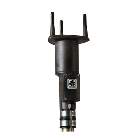
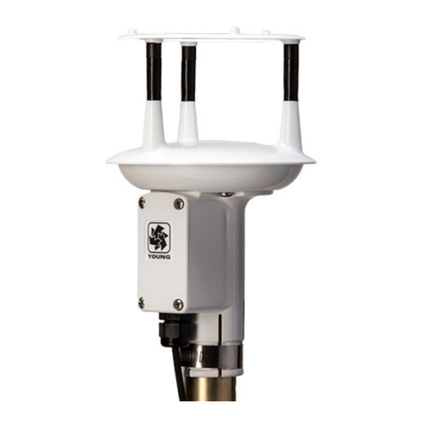
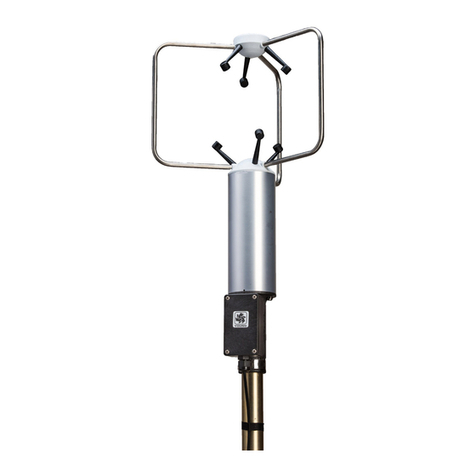
Young 86000-SDI User manual

METEOROLOGICAL INSTRUMENTS
INSTRUCTIONS
R.M. YOUNG COMPANY 2801 AERO PARK DRIVE, TRAVERSE CITY, MICHIGAN 49686, USA
TEL: (231) 946-3980 FAX: (231) 946-4772 WEB: www.youngusa.com PN: 86000-SDI-90
REV: G051820
ULTRASONIC ANEMOMETER
MODEL 86000-SDI

86000-SDI-90(G)
Page 1
MODEL 86000-SDI
ULTRASONIC ANEMOMETER
1.0 SPECIFICATIONS
WIND SPEED
Range: 0-75 m/s (168 mph)
Resolution: 0.01 m/s
Accuracy: 0 to 30 m/s ±2% or 0.1 m/s
30 to 75 m/s ±3%
WIND DIRECTION
Azimuth Range: 0-360 degrees
Resolution: 0.1 degree
Accuracy: ± 2 degrees
SERIAL CONNECTION
Interface Type: SDI-12 v1.3
GENERAL
Power Supply: 10 to 16 VDC
4 mA typical, 85 mA max
Protection Class: IP65
EMC Compliance: FCC Class A digital device
IEC standard 61326-1
Dimensions: 29 cm high x 11 cm wide
Weight: 0.4 kg (0.9 lb)
Shipping Weight: 1.6 kg (3.5 lb)
Operating Temperature: -40 to +60°C
2.0 INTRODUCTION
The YOUNG 86000-SDI Ultrasonic Anemometer is a 2-axis, no-
moving-parts wind sensor with SDI-12 interface. The sensor is
ideal for general meteorological applications requiring accurate
and reliable measurement. The sensor features wide operating
range, compact size, easy installation and low power operation.
The 86000-SDI measures wind speed and direction based on the
transit time of ultrasonic pulses between three transducers.
Measurement results are available in either polar (speed and
direction) or Cartesian (u and v) format using standard SDI-12
commands. Extended SDI-12 commands can be used to set all
signicant operating parameters.
The sensor uses ultraviolet-stabilized thermoplastic for superior
environmental resistance. It is easily mounted on standard 1 inch
(IPS) pipe. An orientation ring preserves mounting position when
the sensor is removed.
The 86000-SDI arrives fully calibrated and ready to use. Connect
as shown in wiring diagram.
TEST COMPLEX CONFIGURATIONS
BEFORE INSTALLATION IN THE FIELD.
3.0 INSTALLATION
3.1 PLACEMENT
Proper instrument placement is important. Eddies from buildings,
trees, or other structures can inuence measurements. For most
applications, locate the sensor well above or upwind of obstructions.
As a general rule, air ow around a structure is disturbed to 2 times
the height of the structure upwind, 6 times the height downwind, and
up to 2 times the height of the structure above ground.
3.2 MOUNTING AND ALIGNMENT
Mount the sensor to standard 1-inch (IPS) pipe that has an outside
diameter of 1.34 inches (34 mm).
Most applications require aligning the sensor to geographic north (0
degrees). In this orientation the sensor junction box faces SOUTH
(180 degrees). See the diagram in APPENDIX B.
3.2.1 Place orientation ring over pipe with guide pin up.
3.2.2 Place sensor mounting post over pipe.
3.2.3 Using the transducers as a sighting aid, align the sensor
with a feature on the horizon that represents the proper
orientation. After alignment, tighten the mounting post
band clamp to secure the position. DO NOT OVER-
TIGHTEN.
3.2.4 Slide the orientation ring up so its guide pin is fully
engaged in the sensor mounting post notch. Tighten the
orientation ring band clamp to secure its position. DO
NOT OVER-TIGHTEN.
If the sensor needs to be removed later, leave the orientation ring on
the pipe to preserve sensor alignment.
3.3 WIRING CONNECTIONS
With long cable lengths, resistance in the power supply wires reduces
the available voltage at the sensor. Power at the sensor must be
in the range of 10 to 16 VDC when the sensor is operating. See
WIRING DIAGRAMS on following pages.

86000-SDI-90(G)
Page 2
4.0 OPERATION
4.1 SDI-12 MEASUREMENT COMMANDS
Model 86000-SDI uses the SDI-12 (v1.3) serial communication
protocol to initiate wind measurements and set sensor operation
parameters. The default sensor address is 0 (zero), and can be
changed to any valid single-character value if needed. Additional
details about the SDI-12 protocol may be found at www.sdi-12.org.
After initial power-up with 12 VDC, the sensor is in a low-power
standby state with a quiescent current of 2.3 mA.
A valid and properly addressed SDI-12 command wakes the sensor
to initiate a wind measurement, or set or check operating parameters.
After command processing has nished, the sensor returns to the
low-power standby state.
SDI-12 'M' or 'C' commands initiate a wind measurement. The sensor
response message indicates the maximum time needed before the
measurement is ready, and that two data values will be available.
The maximum time ranges from 1 to 5 seconds depending on the
Sample Count.
If an 'M' command initiates a measurement, the sensor sends
a Service Request when the wind measurement is ready to be
retrieved. When the polling device receives the Service Request
it then sends a 'D' command to request measurement results from
the sensor. With 'C' commands, no Service Request is sent, and the
polling device must wait the full delay time before sending the 'D'
command to request the measurement.
Measurement commands and responses are listed below.
SDI-12
COMMAND RESPONSE
aM! attt2<CR><LF>
aMC! attt2<CR><LF>
aC! attt02<CR><LF>
aCC! attt02<CR><LF>
aD0! a+www.ww+ddd.d<CRC><CR><LF>
a±uu.uu±vv.vv<CRC><CR><LF>
where:
a= Sensor address
ddd.d = Wind direction (degrees)
www.ww = Wind speed (selected units)
ttt = Delay time (seconds)
±uu.uu = U-axis wind speed (m/s)
±vv.vv = V-axis wind speed (m/s)
<CRC> = CRC checksum (only where requested)
<CR><LF> = Carriage return, line feed (ASCII 13, 10)
Wind data format depends on the sensor Output Format parameter
setting (polar or Cartesian).
4.2 SDI-12 NON-MEASUREMENT COMMANDS
The SDI-12 protocol includes standard commands for identifying the
sensor and changing its address.
SDI-12
COMMAND RESPONSE
?! a<CR><LF>
a! a<CR><LF>
aI! a13 YOUNG 86000 v1.00<CR><LF>
aAb! b<CR><LF>
a= Sensor address
b= New sensor address
4.3 EXTENDED COMMANDS
The SDI-12 command set may be customized with Extended
Commands to accommodate manufacturer settings and other
functions. Extended Commands for the 86000-SDI and the sensor
response are listed below. Where two responses are shown, one
is for a valid command, the other is for an invalid (ERR) command.
Note that only the aXP! command sends a response message.
EXTENDED
COMMAND DESCRIPTION & RESPONSE
aXB! Burn parameter settings to ash.
aXB,OK<CR><LF>
aXFn! n = Output Format code.
0 or 1 (Polar or Cartesian)
aXF,F=n<CR><LF>
aXF,ERR F=0/1<CR><LF>
aXHn! n = Heater Enable.
Not applicable in this model. Do not enable.
aXMnnnnn!
nnnnn = WS Multiplier x 10000 (00000 to 30000)
aXM,M=nnnnn<CR><LF>
aXM,ERR M=00000-30000 ONLY<CR><LF>
aXO±nnnn!
±nnnn = Dir Offset (-3600 to +3600 degrees)
aXO,O=±nnnn<CR><LF>
aXO,ERR O=-3600 - +3600 ONLY<CR><LF>
aXP! Parameter report
aXP,H=h,F=f,U=u,T=t,S=s,W=w,O=o,M=m,V=v<CR><LF>
a = Sensor address
h = Heater enable
0=Disabled, 1=Enabled, 2=Test
f = Wind format 0=Polar, 1= Cartesian
u = Polar wind speed units
1=mph
2=knots
3=km/h
4=m/s
t = Threshold, polar only (0-150 cm/s)
s = Sample count, internal (1-800)
w = Wait (seconds)
o = Wind Direction Offset (degrees)
m = Wind Speed Multiplier
v = Supply Voltage (VDC)
aXSnnn! nnn = Sample Count (001-800 samples)
aXS,S=nnn<CR><LF>
aXS,ERR S=001-800<CR><LF>
aXTnnn! nnn = Wind Speed Threshold
000 to 150 cm/s
aXT,T=nnn<CR><LF>
aXT,ERR T=000-150<CR><LF>
aXUn! n = Wind Speed Units code
1=mph
2=knots
3=kmph
4=m/s
aXU,U=n<CR><LF>
aXU,ERR U=1/2/3/4<CR><LF>
IMPORTANT! PARAMETER CHANGES MUST BE STORED
IN FLASH MEMORY USING THE aXB! COMMAND OR THEY
WILL REVERT TO PREVIOUSLY STORED VALUES AT
POWER UP. The aXB! command may be sent after all changes
have been made, or not sent at all if the changes are temporary.
(Continued on following page)

86000-SDI-90(G)
Page 3
HEATER ENABLE (aXHn!)
This enables, disables, or tests the heater control circuit. Disabling
the heaters removes power from the control circuit. If the Test option
is used, limited power is continuously sent to each heater zone to
test heater function at room temperature
SAMPLE COUNT (aXSnnn!)
This command sets the number of internal samples used to
calculate the median measurement result. More internal samples
consume more power while providing greater immunity to conditions
like turbulent high-speed wind. Fewer samples consume less
power while providing less immunity to disruptive conditions.
Default setting is 100.
THRESHOLD (aXTnnn!)
Threshold sets the minimum wind speed needed before a new polar
wind direction is calculated. The default value is 25 cm/s (0.25 m/s).A
greater-than-zero threshold can help provide more meaningful scalar
wind direction averages. The threshold for Cartesian (u-v) output
format is automatically zero regardless of this setting.
WIND SPEED MULTIPLIER (aXMnnnnn!)
All wind speed measurements are multiplied by this parameter. The
default value is 10000 for a multiplier of 1.0000.
WIND DIRECTION OFFSET (aXO±nnnn!)
Use this parameter to add or subtract a wind direction offset. Value
is degrees x 10 and may be positive or negative. Wind direction is
always re-scaled to a 0-360 range after offset is applied. The default
value is 00000.
4.4 LOW POWER OPERATION
With default settings and a 2-second sampling period, the average
current consumption is less than 4 mA. Average current consumption
may be reduced further by making fewer measurements (one every
5 or 10 seconds, for example) or lowering the Sample Count to
fewer than 16. Lowering the Sample Count below 16 may limit
measurement accuracy in winds greater than 30 m/s.
4.5 TROUBLESHOOTING
Symptom: After using setup program, SDI-12 mode is disabled.
(Note: Setup program is only for RS232 mode.)
Cause: Saving parameters in setup program disables SDI-12
mode.
Solution: While in RS232 command mode, send the following
commands via the “Communications” tab in the setup
software or via a terminal program to re-enable
SDI-12 mode. (“>” is the command prompt):
>SET025
>SET77
Power cycle the sensor.
Sensor will be in SDI-12 mode.
WIRING DIAGRAM
Use shielded cable. Connect cable shield to earth ground as shown.
Model 86000-SDI
Ultrasonic Anemometer
5.0 EMC COMPLIANCE
This device complies with Part 15 of the FCC Rules. Operation is subject
to the following two conditions: (1) this device may not cause harmful
interference, and (2) this device must accept any interference received,
including interference that may cause undesired operation.
This equipment has been tested and found to comply with the limits
for a Class A digital device, pursuant to part 15 of the FCC Rules.
These limits are designed to provide reasonable protection against
harmful interference when the equipment is operated in a commercial
environment. This equipment generates, uses, and can radiate radio
frequency energy and, if not installed and used in accordance with
the instruction manual, may cause harmful interference to radio
communications. Operation of this equipment in a residential area
is likely to cause harmful interference in which case the user will be
required to correct the interference at his own expense.
This ISM device complies with Canadian ICES-001.
Cet appareil ISM est conforme à Ia norme NMB-001 du Canada.
EN55011/CISPR 11, Group 1, Class B device.
Class B equipment is suitable for use in domestic establishments and
in establishments directly connected to a low voltage power supply
network which supplies buildings used for domestic purposes.
6.0 WARRANTY
This product is warranted to be free of defects in materials and construction
for a period of 12 months from date of initial purchase. Liability is limited
to repair or replacement of defective item. A copy of the warranty policy
may be obtained from R. M. Young Company.
7.0 CE COMPLIANCE
This product has been tested and complies with European
CE requirements for the EMC Directive. Please note that shielded
cable must be used.

86000-SDI-90(G)
Page 4
SENSOR ORIENTATION AND DIMENSIONS
Table of contents
Other Young Measuring Instrument manuals

Young
Young 81005A User manual

Young
Young Wind Sentry Series User manual

Young
Young 27106T User manual

Young
Young 81000V User manual

Young
Young 06201 User manual

Young
Young 06201 User manual

Young
Young 85000 User manual

Young
Young 32400 SERIAL INTERFACE User manual

Young
Young 09101 User manual

Young
Young WIND MONITOR-AQ 05305 User manual