EIUK PTB 600 User manual

PTB600-MAN-V10.4 PTB 600 Instruction Manual
1
PTB 600
Portable Temperature Calibrator
Instruction Manual
Eurotron Instruments (UK) Ltd
Unit 13 Riley Close, Royal Oak Industrial Estate
NN11 8QT- Daventry, United Kingdom
T+ 0044 (0) 1327 871044
F: 0044 (0) 1327 301 255
www.eurotron-uk.com
info
@
eurotron-uk.com

PTB600-MAN-V10.4 PTB 600 Instruction Manual
2
INSTRUCTIONS MANUAL REV. DATA
PTB600 10.4 Oct.: 2011
VALID FROM SERIAL NUMBER K322 11
INDEX
WARNING ..........................................................................................................................................................3
1 - INTRODUCTION...........................................................................................................................................4
1.1 -PURPOSE AND SUMMARY OF INSTRUCTIONS................................................................................................4
2 - SCOPE OF SUPPLY.....................................................................................................................................5
2.1 -NAME: ......................................................................................................................................................5
2.2 -TECHNICAL DATA: .....................................................................................................................................5
2.3 -SERVICE (FUNCTION):................................................................................................................................6
2.4 -QUANTITY:................................................................................................................................................6
2.5 -CONSTRUCTOR: ........................................................................................................................................7
2.6 -N° OF CORRESPONDENT CATALOGUE SHEET: .............................................................................................7
2.7 -LIST OF FIRST EQUIPMENT ACCESSORIES:...................................................................................................7
3 - GENERAL RECOMMENDATIONS..............................................................................................................8
4 - SAFETY INSTRUCTIONS ............................................................................................................................9
5 - PREPARATION OF OPERATION..............................................................................................................10
5.1 -INSTALLATION.........................................................................................................................................10
5.1.1 - Removal of packaging.................................................................................................................10
5.1.2 - Positioning the calibrator............................................................................................................10
5.1.3 - Supply ...........................................................................................................................................10
6 - OPERATION PROCEDURE.......................................................................................................................12
6.1 -OPERATION DESCRIPTION ........................................................................................................................12
6.2 -DESCRIPTION OF INSTRUMENT..................................................................................................................12
6.2.1 - Thermoregulator ..........................................................................................................................12
6.2.2 - Main switch...................................................................................................................................12
6.2.3 - Carrying handle............................................................................................................................12
6.2.4 - Heating resistance.......................................................................................................................12
6.2.5 - Equalising block...........................................................................................................................13
6.2.6 - Temperature sensors...................................................................................................................13
6.2.7 - Safety thermostat.........................................................................................................................13
6.3 -START-UP INSTRUCTIONS.........................................................................................................................14
6.4 -USE OF THE FUNCTIONS...........................................................................................................................16
6.4.1 - Reading the external probes (only for TC version)..................................................................16
6.4.2 - Switch test (SW. ON SW. OFF) ..................................................................................................17
6.4.3 - Serial communication..................................................................................................................17
7 - MAINTENANCE INSTRUCTIONS..............................................................................................................17
7.1 -ROUTINE INSPECTIONS INSTRUCTIONS......................................................................................................17
8 - SEQUENCE OF MAINTENANCE..............................................................................................................17
9 - TYPICAL FAULTS......................................................................................................................................18
10 - APPENDICES...........................................................................................................................................19
10.1- REGULATION FRONT PANEL ...................................................................................................................19
10.3 -COMMUNICATION PROTOCOL RS232/C..................................................................................................26
10.4 -LIST OF SPARE PARTS:230V MODEL......................................................................................................29
10.5- DECLARATION OF CONFORMITY AND CHECK REPORT................................................................................29
10.6 -DRAWING AND WIRING DIAGRAM ............................................................................................................29
PTB600-MAN-V10.4 PTB 600 Instruction Manual
3
WARNING
Hazardous voltages are present in this electrical equipment during operation.
Non-observance of the safety instruction can result in severe personal injury or property
damage.
Only qualified personnel should work on or around this equipment after becoming
familiar with all warnings, safety notices, and maintenance procedures contained herein.
Only qualified personnel or our personnel should work on this equipment for
maintenance operation.
The successful and safe operation of this equipment is dependent on proper handing,
operation and maintenance.
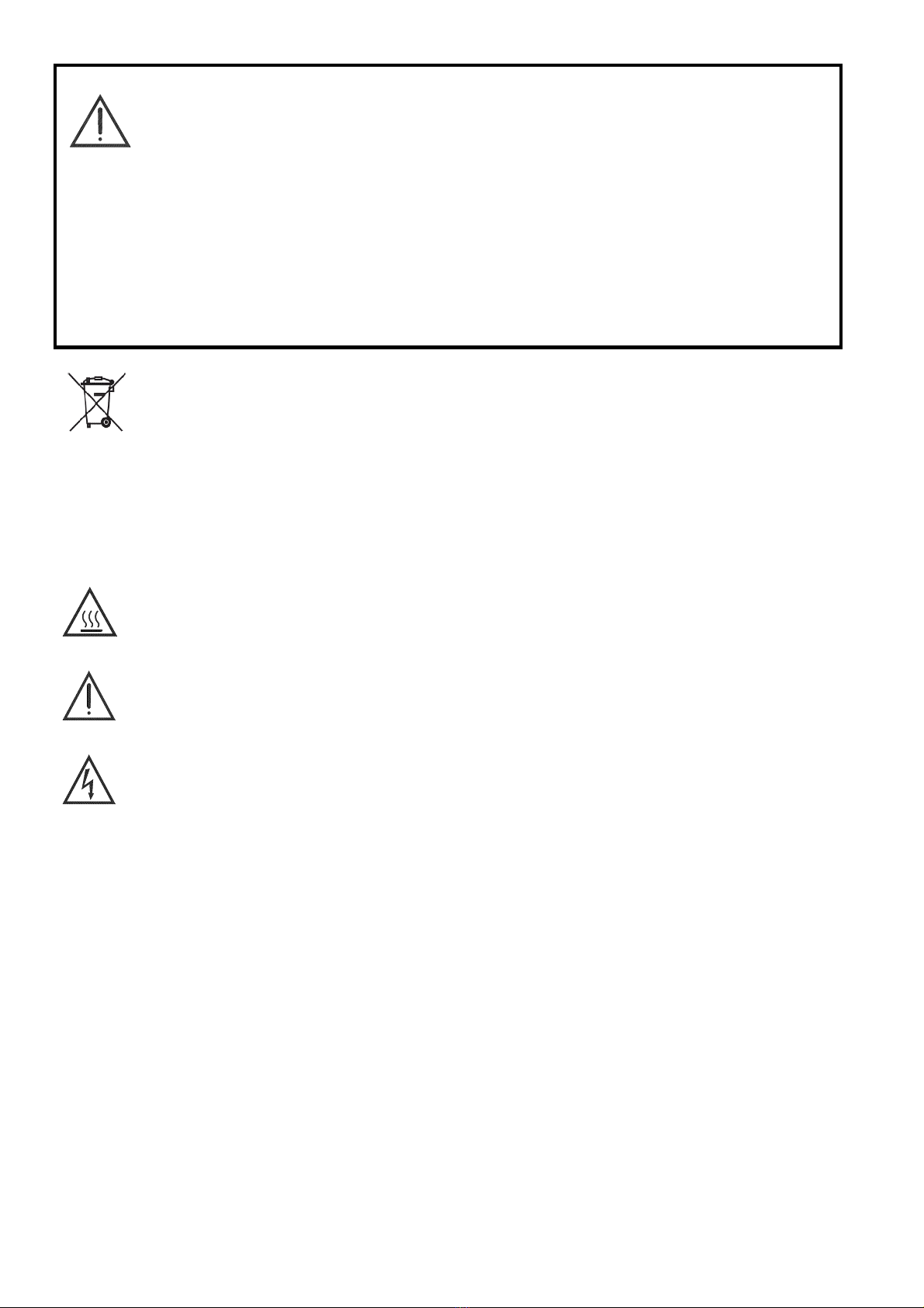
Electrical and electronic equipments with this symbol cannot be thrown away in public
dump sites. According to the EU directive 2002/96/EC, the European users of electrical
and electronic equipment have the opportunity to return to the distributor or manufacturer
used equipment purchasing a new equipment. The illegal disposal of electrical and
electronic equipments is punished by pecuniary administrative sanction.
SYMBOLS BEING USED IN THIS MANUAL OR ON THE INSTRUMENT
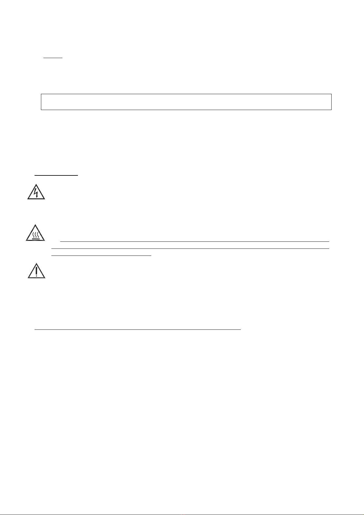
CAUTION: HOT SURFACE OR PART
CAUTION: REFER TO ACCOMPANING DOCUMENTS
CAUTION: RISK OF ELECTRICAL SHOCK
Note:
In this manual: where not specified, the numbers in parentheses make reference to the annexed
drawing.

PTB600-MAN-V10.4 PTB 600 Instruction Manual
4
1 - INTRODUCTION
1.1 - Purpose and summary of instructions
This manual contains instructions for use and maintenance of the family of temperature calibrators
PTB600‐TS‐230‐UKTemperatureCalibrator,Tambto600⁰CTSversion230VAC
PTB600‐TS‐115‐USTemperatureCalibrator,Tambto600⁰CTSversion116VAC
PTB600‐TS‐230‐EUTemperatureCalibrator,Tambto600⁰CTSversion230VAC
PTB600‐TC‐230‐UKTemperatureCalibrator,Tambto600⁰CTCversion230VAC
PTB600‐TC‐115‐USTemperatureCalibrator,Tambto600⁰CTCversion115VAC
PTB600‐TC‐230‐EUTemperatureCalibrator,Tambto600⁰CTCversion230VAC
The instructions reported in this manual, for the above-mentioned equipment, are those relevant to:
* Start-up preparation
* Operation description
* Using of the equipment
* Re-calibration procedure
* Preventive maintenance
* Typical faults and ways of their remedies
Users must observe all the usual safety rules out in this manual for own security and to avoid equipment
failure.

PTB600-MAN-V10.4 PTB 600 Instruction Manual
5
2 - SCOPE OF SUPPLY
2.1 - Name:
Portable Temperature Calibrator PTB600, including accessories, as listed (reference to paragraph 2.7)
2.2 - Technical data:
Structure in flanged plate with handle.
Micro-processor operated temperature regulator.
Safety thermostat with thermocouple.
Switch test.
Internal oven in stainless steel.
Electronic control components thermally insulated.
Forced air cooling system.
Removable upper protection grid.
Total absence of environmentally harmful cooling liquids.
Socket with main cable and protection fuses.
Display back light control.
Electromagnetic compatibility : Emission EN50081-2
Immunity EN50082-2
Model with copper block measuring 50mm diameter and insert of diameter 35mm
PTB60035CU-xx-x
Operative range : Environment ÷ +600°C**
Stability : ±0.05°C a 450°C **
Reading accuracy : ±0,3°C a 450°C
Maximum ascent rate : 20÷22°C/1’ **
Maximum descent rate : 6÷10°C/1’ ** (t = 300°C).
Standard insert : 5 holes ø3,2-4,5-6,5-9,5-11,5 x 185mm
Weight of calibrator : 10Kg
Display resolution : 0,01/0,1°C
Reading accuracy : ±0,3°C a 450°C
Regulation & reading probe : Pt 100 class A din43760
Auxiliary input : Pt100 and Tc J, K, N, R, S, E(only for Model 2I)
Reading : °C or °F or K.
Interface : RS 232
Temperature ramps : minimum 0,1°C/1’
Thermostat test : 12 Vcc.
Power supply : 230V 50/60Hz (110/115V by request)
Power : 800VA.
Size : 140x370 x 330 mm
Case size : 330x520 x H. 500 mm
Customized insert with drilled holes for best accuracy
NOTE: The data marked with ** has been recorded at an ambient temperature of 20°C±3, power supply
230V±10%, with Pt100 ø4.5mm inserted in the block.
The above-mentioned data keep valid for one year after the issuing of the calibrating certificate;
afterwards it is necessary to carry out the oven re-calibration.
Environmental range: temperature +10 ÷ +45°C, R.H. max. 80%.
MICROPROCESSOR DATA
* Display : 2 lines 20ch x line (3.2x5.5) back lighting.
* Resolution : 0.01°C/0.1°C.
* processor : 80C552
* A/D converter : Σ-∆24 bits
* E2PROM memory for recording parameters.
* RS232 Single serial output.

PTB600-MAN-V10.4 PTB 600 Instruction Manual
6
2.3 - Service (function):
The portable temperature calibrator PTB600 has been designed for:
Control & calibration of thermocouples, temperature sensors... , in the laboratory and in the field, in
conformity with ISO 9000 standard.
Thermal test on materials.
The calibrator has been designed to reduce the EMC effect in accordance with the harmonised regulation for
residential, commercial, light industry and heavy industry.
N.B: PTB600 endowed with WindowsTM Software is designed to:
completely check the oven by PC
automatically or manually calibrate many probes
cyclically check temperature sensor long life or stress condition
register and print results obtained according to ISO 9000 standards.

PTB600-MAN-V10.4 PTB 600 Instruction Manual
7
2.4 - Quantity:
1 piece.
2.5 – Manufacturer
Eurotron Instruments (UK) Ltd
Unit 13 Riley Close, Royal Oak Industrial Estate
NN11 8QT- Daventry, United Kingdom
T+ 0044 (0) 1327 871044 F: 0044 (0)1327 301 255
www.eurotron-uk.com
2.6 - N° of correspondent catalogue sheet:
PTB-D-V02 ( 15112011)
2.7 – Ordering Code:
PTB600‐TS‐230‐UKTemperatureCalibrator,Tambto600⁰CTSversion230VAC
PTB600‐TS‐115‐USTemperatureCalibrator,Tambto600⁰CTSversion115VAC
PTB600‐TS‐230‐EUTemperatureCalibrator,Tambto600⁰CTSversion230VAC
PTB600‐TC‐230‐UKTemperatureCalibrator,Tambto600⁰CTCversion230VAC
PTB600‐TC‐115‐USTemperatureCalibrator,Tambto600⁰CTCversion115VAC
PTB600‐TC‐230‐EUTemperatureCalibrator,Tambto600⁰CTCversion230VAC
PTB600‐INS‐01blankinsertDN.35x190mm
PTB600‐INS‐02InsertDN35x190mmwith5holes:φ.3,5‐5.0‐6,5‐8,5‐12,5mm.
PTB600‐INS‐03InsertDN35x190mmcustom(max5holesfrom3,5to20mm)
PTB600‐INS‐04InsertDN35x190mmcustom(max3holesfrom3,5to20mm)
PTB600‐INS‐05InsertDN35x190mmcustom(max2holesfrom3,5to20mm)
PTB600‐INS‐IRBlackbodyInsertDN35x190c/wReferenceSensor
PTB600‐TC‐OPT‐01SRS‐PRT‐45‐190Breferencesensorandspecial UKAScalibration
PTB‐CASE‐02AluminiumTransportCasewithspaceforaccessories(PTB/PLB)
PTB‐CASE‐01VinylCasewithPocketsforaccessories(PTB/PLB)
Certification: all the instruments are supplied with final testing, stability and accuracy certification
traceable to International standards. UKAS calibration available on request

PTB600-MAN-V10.4 PTB 600 Instruction Manual
8
3 - GENERAL RECOMMENDATIONS
ATTENTION
The processor regulator has been configured in factory with the parameters suited to work in the
respect of the technical specifications.
Don’t change these parameters to avoid malfunction or breaking of the calibrator with risks of
serious personal injury.
- Position of the probe:
To obtain the best results, follow the advises:
Measure the diameter of the probe being checked.
Check that the diameter of the hole in the calibration block is
1. at least 0.5mm bigger than the diameter of the probe for diameter of the probe up to 8mm,
2. at least 0.7mm bigger than the diameter of the probe for diameter of the probe up to 12mm,
3. at least 0.5mm bigger than the diameter of the probe for diameter of the probe up to 8mm . If this is
not the case If this is not the case use the reduction wells with the above-mentioned tolerances
(fig.1).
Avoid using holes that are too accurate and do not force the probes into the block.
Put the probe or the insert in the block only at ambient temperature; for reduction insert using the tweezer
Insert the probe up to the bottom of the block: the sensitive element is in the optimal calibration zone (fig. 2).
Calibration with a reference: take care to position the two probes, the standard one and the calibration
one, at the same dept and as close together as possible (fig. 3).
Always verify the range of the probes to be calibrated before using; the maximum temperature of the probes
should be higher then the internal temperature otherwise the probe could break
Fig.1 Fig.3Fig.2
PTB600-MAN-V10.4 PTB 600 Instruction Manual
9
- Advice:
The temperature difference is proportional to the difference between the diameter of the probe and the
diameter of the hole.
Do not insert the probe when the instrument has already reached the set temperature; thermal shock
causes instability and breakage of the sensitive element.
For the calibration of temperature transducer with special execution, call our technical office and ask for
equaliser block with special drillings.
REMEMBER TO SET THE AMBIENT TEMPERATURE AND LEAVE COOL THE
CALIBRATOR BEFORE SWITCHING OFF
4 - SAFETY INSTRUCTIONS
ATTENTION:
Due to the fact that the calibrator is a portable instrument to be used in the field, it is very important
to ensure that the socket has been earthen correctly when connecting it to the power supply.
Carry out the maintenance and repair operation only with the equipment at ambient temperature
and disconnected from the electric power.
During the use of the calibrator, the upper protection grid may overheat.
Don’t touch the probe to calibrate when it’s in the block.
After using wait for the stabilisation at ambient temperature before returning the calibrator to its
carrying case. Don’t switch off the calibrator when it works at high temperature because the protection
grid and the carpentry may overheat.
Never put any type of liquid inside the block.
Don’t change absolutely the configuration parameters
Don’t put anything on the top of the calibrator.
Do not connect any voltage higher then 5V to the input 4-5-15
Don’t put fuel objet near the calibrator.
...... use common sense any time.
The equipment adopt the following devices to protect operation from hazard:
Max. temperature safety thermostat (10) to disconnect the heating system.
Protection grid to avoid any contact with the internal oven.
Protection fuses (3)
Ground conductor.

PTB600-MAN-V10.4 PTB 600 Instruction Manual
10
5 - PREPARATION OF OPERATION
Remove the calibrator from the packaging (5.1.1) and place it on a flat surface (5.1.2).
Make sure that the instrument has been correctly earthen.
Supply the oven with line 230V, 50Hz + earth (5.1.3).
Insert the equalising block into the furnace: reference at the instruction on paragraph 5.1.4
Before start the calibration read with attention the instruction manual, specially the paragraph 3: -
General recommendation.
5.1 - Installation
5.1.1 - Removal of packaging
The calibrator is equipped with packaging suitable for transport and traditional shipping systems. Any
damage caused during transport must be notified immediately to the carrier and a claim must be made.
5.1.2 - Positioning the calibrator
Position the calibrator in a safe clean place; leave enough space around the calibrator to allow the air to
circulate well.
**DANGER: The calibrator is suitable for operating at high temperatures with the consequent danger of
fire. Keep it away from any type of inflammable materials and, never put any type of liquid
inside the block (reference to paragraph 4)
* WARNING: To avoid any smell in the room it is better to switch on the calibrator outside the room for the
first time
5.1.3 - Supply
The calibrator runs on a voltage of 230 Vac (115V by request), 50/60Hz.
A 2.5mt. cable is supplied with the calibrator fitted with 2 conductors plus earth.
Make sure that the plant is earthen correctly before switching the instrument on.

PTB600-MAN-V10.4 PTB 600 Instruction Manual
11
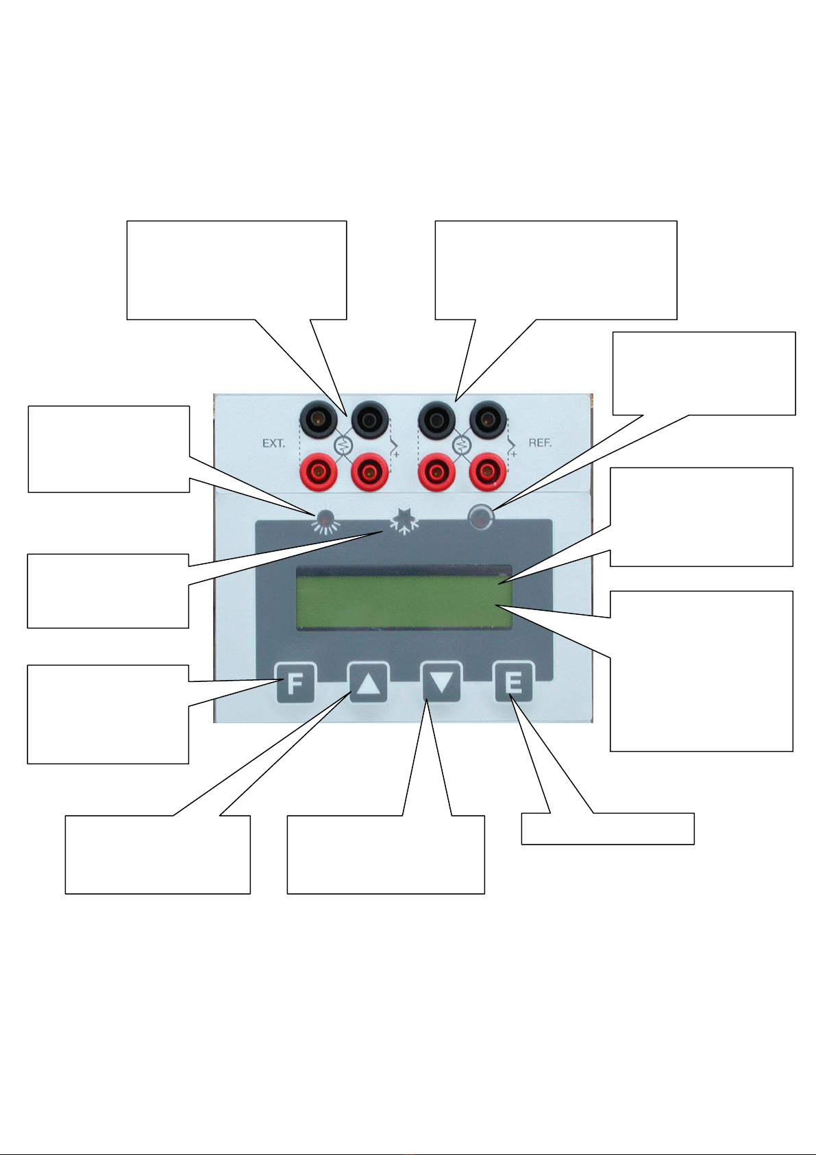
COMMAND LIST
POS. DESCRIPTION
1 SUPPLY SOCKET
2 MAIN SWITCH
3 PROTECTION FUSES
4 SWITCH TEST BUSHES
5 RS-232 SOCKET
7 THERMOREGULATOR +DISPLAY
7.1 HEATING LED
7.2 COOLING LED
7.3 SWITCH TEST LED
15 EXTERNAL PROBES SOCKETS (TC version only)
7
7.1
7.2
7.3
15
54
23
1

PTB600-MAN-V10.4 PTB 600 Instruction Manual
12
6 - OPERATION PROCEDURE
6.1 - Operation description
The PTB600 calibrator consist of an anticorodal block fitted with holes into which the sensors to be calibrated
are inserted.
A heater element heats the block and an electronic μcontroller with Triac output checks and regulates the
temperature.
A fan mounted in the rear side generates a constant air flow that reduces the temperature of the case.
6.2 - Description of instrument
6.2.1 - Thermoregulator
The thermo-regulator (7) is a PID microprocessor, which can be set from 0 to 550°C.(600 for model BA)
DISPLAY UPPER LINE: indication of the temperature measured inside the block.
DISPLAY LOWER LINE: indication of the set point; external probes if selected, setting parameters .
KEY: used to increment (decrement) any numerical parameter. The increment (decrement) speed is
proportional to the time the key remains depressed.
F KEY: allow access to the various parameters (repeatedly press), access to the various phases of
configuration (press F +).
E KEY: allow confirming the set parameter.
The calibrator is endowed with eight terminals (optional) that can be set as Pt100 or Tc.
6.2.2 - Main switch
The main switch (2) is fitted with a socket for the voltage cable, the main switch and two fuses as for the
following table:
MODEL V230 V110/115
PTB600-TC
PTB600-TS
5A 10A
Note: use only fuses F. 5x20mm. All the electrical part is found below the main switch.
6.2.3 - Carrying handle
The calibrator is fitted with a carrying handle .
6.2.4 - Heating resistance
The resistance (13) is stainless steel made; the max. power is 800W (1200W for the ¢65, 230V models)
and it can reach temperatures approaching 600°C.
Bear in mind, however, that constant use at extreme temperatures reduces the life of the resistance itself.
Limit the number of hours at which the resistance is used at maximum temperatures to the time required by
the calibrator in order to prolong the life of the resistance.

PTB600-MAN-V10.4 PTB 600 Instruction Manual
13
6.2.5 - Equalising block
The function of the block is to make the temperature uniform on calibration zone.
If you want to fit the calibrator with a block with different holes we recommend that you should contact the
technical support department who will check to see if it is feasible. This will avoid any unfortunate problems
which might arise if the wrong tolerances are used. The equalization block is in aluminium, Aluminium-
Bronze or Copper depending on the models; holes have been made on the inside to make it possible to fit
various types of probes.
6.2.6 - Temperature sensors
The temperatures sensor used for regulating is a Pt100 and the temperature sensors used to protect the
instrument is a thermocouple.. Both are inserted directly into the equalization block so as to supply a
temperature value close to the real value in the block. There could, however, be some differences due to the
tolerances of the sensors themselves.
6.2.7 - Safety thermostat
The calibrator is supplied with max. temperature safety thermostat (10) that disconnect the heating system.
In case the thermostat intervenes:
Waiting the cooling of calibrator: the temperature must decrease at least 60÷80°C respect to maximum
set point.
Switch off the calibrator then switch on again a few second later on.
If problem persist: disconnect the electrical cable to the oven and proceeding to repair of eventual faults
(reference to paragraph 4); therefore switch on the oven. Consulting chapter 9 – typical faults – for any
problems on the thermostat.
N.B.: the thermostat mounted on standard ovens has been calibrated in factory to intervene at 560 or 610°C
±5°C depending on the models.
PTB600-MAN-V10.4 PTB 600 Instruction Manual
14
6.3 - Start-up instructions
ATTENTION:
The calibrator can only be used correctly if the user has a good knowledge of its basics.
Before starting with the calibration following the instructions for the positioning of the equalising block
(paragraph 5); carefully read paragraph 3 and 4.
To calibrate the probe it is possible to follow two ways: calibration with internal indicator (7), or calibration
with external reference.
Calibration with the internal indicator (7):
Make reference to the temperature value of the display (7:
fig.4).
It is opportune to refer the value to the test report to
compensate the error of the display.
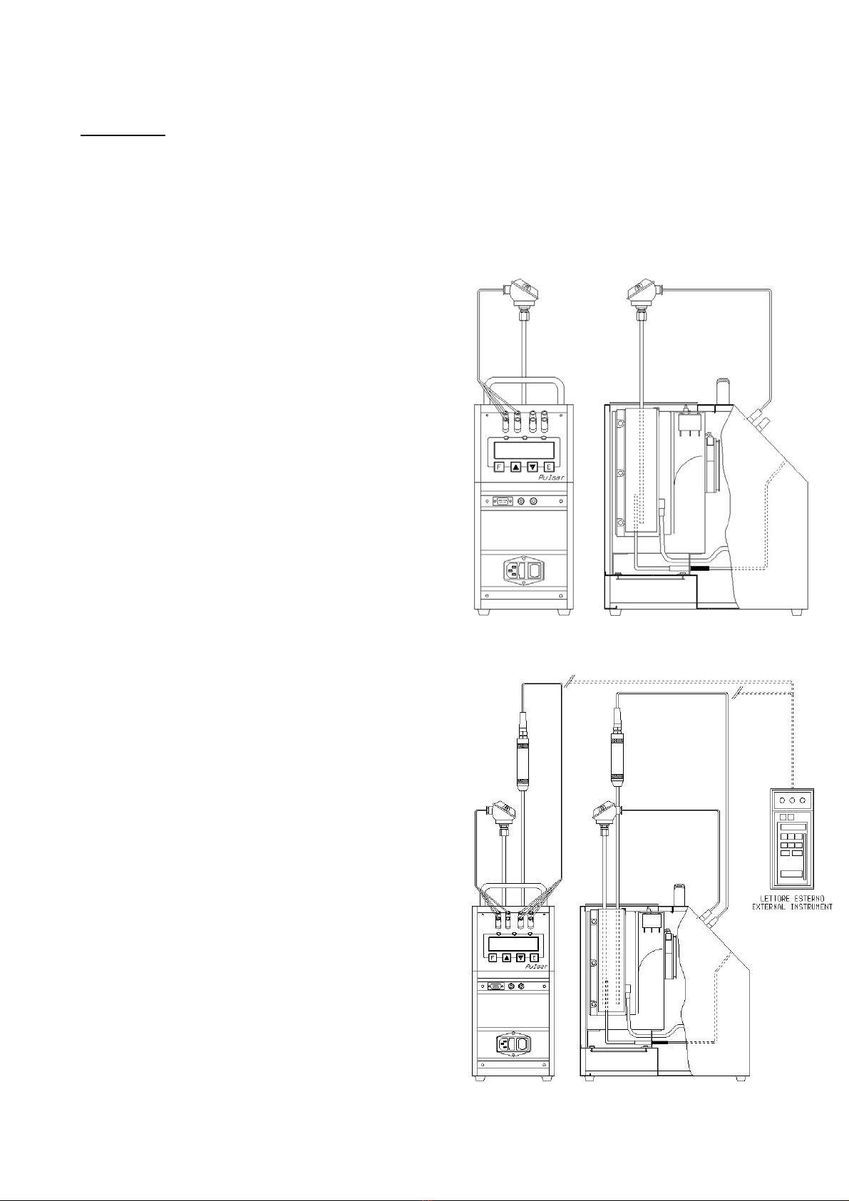
Calibration with external reference and reading on the
calibrator display:
Make reference to the temperature value of the external
standard instrument inserted in the equalizer block and
connected directly to the Solar (Fig.5); temperature is read
on the second line of display (for the configuration of the
external reference seeing 10.1). When possible: put the
sensitive elements of the probes near and at the same dept
(reference to Fig.1-3)
Calibration with external reference and reading on an
external instrument:
Make reference to the temperature value of the external
standard instrument inserted in the equalizer block and
connected to an external instrument (Fig. 5). When
possible: put the sensitive elements of the probes near and
at the same dept (reference to fig.1-3).
Fig.4
Fig.5

PTB600-MAN-V10.4 PTB 600 Instruction Manual
15
Before any calibration follow the general recommendation:
Starting the calibration only at ambient temperature: thermal shock can break the sensitive element of the
probe and cause harm to operator.
To fit the equaliser block inside the oven: reference to paragraph 5.1.4.
Put the probe to check into the equaliser block: reference to chapter 3 (fig 1-3).
Push on the main switch (2) and waiting for the end of autotest procedure.
Set the required temperature value on the set point following the instructions below:
Press the
key to increment the set point value.
Press the
key to decrement the set point value.
Press the E key to confirm
Wait for the stabilisation of the oven before starting any calibration (symbol ÷ on the first line of the
display).
To working at different temperatures set the set point at the new value and wait for the stabilisation.
When the set point is changed, the temperature read on the display and that measured in the block may
not proceed at the same speed; this is because there are differences between the sensors used and the
position of the same inside the block.
The temperature indicated by display must not be considered as a reference temperature but only as a
general indication of the temperature inside the block.
We suggest to insert a primary standard in the block; compare the measure with the values indicated by
the standard.
Don't ever use the primary standard: it's possible to calibrate the instrument to more significant points,
comparing the displayed temperature with the temperature of the primary standard.
ATTENTION:
At the end of the calibration DO NOT remove the probe if it is still at high temperature. Always
allow the calibrator to cool off with the probe still inserted in order to avoid thermal shock to the probe
itself and harm to people or things.
Before switch off the calibrator make sure that the temperature of the block is almost the same as
ambient temperature.
Cooling:
To reduce the oven’s temperature, change the set point and wait for the cooling.
PTB600-MAN-V10.4 PTB 600 Instruction Manual
16
6.4 - Use of the functions
6.4.1 - Reading the external probes (only TC version)
It is possible to display one or two probes tied to the EXT and REF inputs.
The following probes can be connected:
1. THERMOCOUPLES TYPE J, K, R, S, N, E with automatic compensation
of the terminal clamp temperature.
2. THERMAL RESISTANCE Pt 100 to 2, 3 or 4 wires.
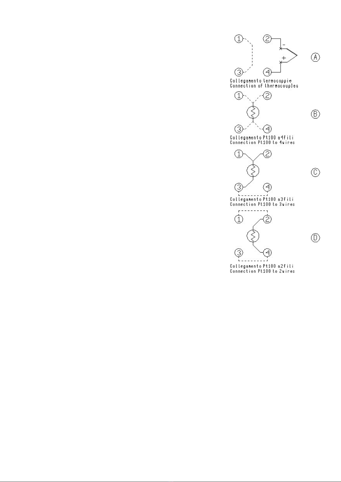
Connect the probe’s wires to the clamps as it is indicated in the figures.
Thermocouple – connect the wires to the clamps 2-4 to make
attention to the polarity; connect the clamps 1-3 as indicated.
Reference to Fig. 7-A
Pt100 to 4 wires – connect the clamps 1-2-3-4 as indicated in Fig.
7-B
Pt100 to 3 wires – connect the wires to clamps 1-2-3; connect the
clamps 3-4. Reference to Fig. 7-C
Pt100 to 2 wires – connect the wires to clamps 2-4; connect the
clamps 1-2 & 3-4. In case of two wires connections remembers to
us shortest wires possible. Refer to Fig. 7-D
In order to read the external probe’s temperature press the Fkey up to
read SENSOR, select EXT or REF or EXT + REF then confirm with E
key. Press theand Fkeys together to jump to the second level of the
parameters, press Fto read EXT SENSOR TYPE and REF SENSOR
TYPE and press the and the keys to select the probe; the
temperature will be displayed on the at the bottom of the display.
Press theand Fkeys together to jump to the first level again , the
temperature will be indicated on the bottom of the display.
In order to read in the '°F' way, refer to the procedure explained in
paragraph 10.1 till Units°C/°F/K; the conversion of the new scale will be
carried out at once.
NOTE: The calibrator always thermally adjusts with the control probe
situated inside the block.
MESSAGE OF ERROR OF THE EXTERNAL PROBES DISPLAY
The display in the case of connection or configuration errors indicates:
EST SENSOR FAIL : wrong connection or configuration of the EXT probe
REF SENSOR FAIL: wrong connection or configuration of the REF probe
SENSORS FAIL: wrong connection or configuration of the REF and EXT probes
Fig. 7
PTB600-MAN-V10.4 PTB 600 Instruction Manual
17
6.4.2 - Switch test (SW. ON SW. OFF)
It is possible to control the intervention point of thermostats by the 'SWITCH TEST' function.
Insert the sensor of the thermostat in the most suitable hole of the calibrator (refer to notes in paragraph 3).
Connect the thermostat’s electrical terminals to the bushes terminals (4).
Turn the equipment on.
Set the thermostat intervention temperature and check the release by the lighting of the indication light
(7.3).
The thermostat’s release values are recorded. In order to display the recorded value, refer to the
procedure explained in paragraph 10.1 till ‘SW ON - SW OFF’.
Press the
and keys at the same time in order to reset the 'SW.ON - SW.OFF' values.
Refer to paragraph 10.1 to set the ascent and descent ramps.
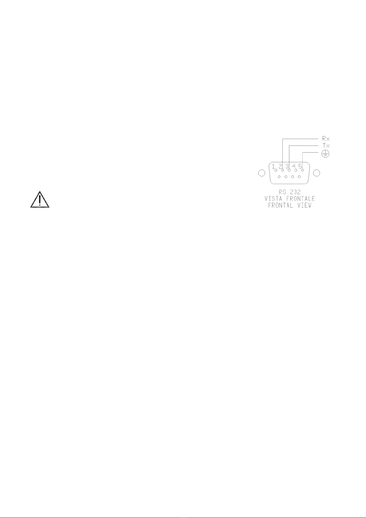
6.4.3 - Serial communication
On the front of the calibrator there is a 9 pole socket (5) connected to the
thermo-regulator, which enables the calibrator to be completely controlled by a
PC (reference to fig.8). The standard adopted RS-232 (contact the technical
department for the communication number).
The external PC must be conform to the IEC950 standard.
7 - MAINTENANCE INSTRUCTIONS
7.1 - Routine inspections instructions
Check that the holes of the calibrator are cleaned, any liquid or oil inside the hole could make oxides or
dirty during the use at high temperature.
Check once a year the calibration date. Frequency of calibration is depending to the use of instrument;
however we suggest to calibrate the instrument every year.
To re-calibrate the instrument is necessary to have a standard temperature instrument, the software
‘CALIBRA’ and follow the instructions of the software or alternately follow the instructions of item 10.1.
8 - SEQUENCE OF MAINTENANCE
Not applicable
Fig.8

PTB600-MAN-V10.4 PTB 600 Instruction Manual
18
9 - TYPICAL FAULTS
Before carrying out these operations the instrument must be disconnect from the electricity supply; the
equaliser block must be at ambient temperature.
N°
FAULT DESCRIPTION
FAULTY COMPONENT OR
FUNCTION METHOD FOR REMOVAL
1
The calibrator does not work
when the power cable is
connected and the main switch is
turned on.
- The fuse (3) is cut off.
- The power cable is cut off.
- The main switch is faulty.
-Replace the fuses.
-Replace the power cable with
a similar one.
-Replace the cup socket (1-3)
2
The fuses (3) are triggered when
the power cable is connected
and the main switch is turned on.
- The power card is faulty.
- Replace the power card.
3
The control panel is working
properly but the temperature
does not increase.
-
-The thermoregulator (7) is
faulty.
-The static relay on the supply
card (11) is faulty.
-The heating element is cut
off.
-The safety thermostat (10)
has been triggered.
-Replace the supply card.
-Replace the thermoregulator.
-Replace the heating resistor
-Reset the thermostat (ref. to
6.2.8)
4
The display indicates a different
temperature from the one
measured in the block.
-The probe (9) is faulty.
-The thermo regulator (7) is
faulty.
- Replace the probe.
- Replace the thermo regulator.
5
The temperature does not stop
at the value of the point that has
been set.
-The supply card (11) is faulty. - Replace the supply card.
6
The temperature does not
decrease to the set value as
quickly as it should.
-The thermo regulator (7) is
faulty.
-The cooling fan (6) is faulty.
- Replace the thermo regulator.
-Replace the fan
7
The display indicates
“Overrange” or RTD failure
-The control probe (9) is cut off
or is in short circuit.
-The thermo regulator (7) is
faulty.
- Replace the thermocouple.
- Replace the thermo regulator
PTB600-MAN-V10.4 PTB 600 Instruction Manual
19
10 - APPENDICES
10.1- Regulation Front Panel
SWITCH TEST LED
When the led is on the
thermostat’s contact is
closed
Confirmation of the values
It reduce the value showed on
the display 2. If you keep
pressed the key “DOWN” the
speed of reduce rises
It increase the value showed
on the display 2. If you keep
pressed the key “UP” the
speed of increase rises
Access to the function
menu.
Pressed with the key
it let you enter to the ‘Set
Up’ menu
DISPLAY 2
Indication of the value of the
set point.
Indication of the external
probe if selected.
During the program
operation it shows the
parameter selected by the
‘F’ key.
DISPLAY 1
It shows the value of the
variable temperature or the
engineer unit
COOLING LED
When the led is on the
calibrator decrease the
temperature
HEATING LED
When the led is on the
calibrator increase the
temperature
EXTERNAL PROBE INPUT
Selectable between Pt100, Pt100
3W, Tc K, Tc S, Tc N, Tc J, Tc R,
Tc E type according to the probe
you calibrate
REFERENCE PROBE INPUT
Selectable between Pt100, Pt100
3W, Tc K, Tc S, Tc N, Tc J, Tc R, Tc
E type according to the probe you
calibrate

PTB600-MAN-V10.4 PTB 600 Instruction Manual
20
DESCRIPTION OF REGULATOR’S MENU
The calibrator has three menu levels( see image 10.2):
at the first level there are the functions for the continuous usage,
at the second level there are more specific functions for the regulation of the calibrator,
at the third level there are the typical functions for each calibrator and the calibration procedures.
1st MENU LEVEL
PRESS THE FKEY TO STEP THROUGH THE MENU
- SP
SET POINT: temperature set which the oven has to reach following technical specifications, press the
or key to adjust the set point and press E key to accept new the new value.
- SP2
SET POINT2: temperature set which the oven reaches with the set gradient and the ongoing launched
ramp procedure, press the or key to adjust the set point and press E key to accept new the new
value.
- GRAD
GRADIENT: set point variation speed during the change from one temperature value to the SP2 value,
press the or key to adjust the set point and press E key to accept new the new value.
The set gradient must be negative for descent ramps.
NOTE: gradient values to be set must be lower than the ones stated in the technical data, at point 2.2
(cooling grad. max.: -7°C/min.; heating grad. max. 18°C/min).
- RAMP
Ramp procedure enabling/disabling.
Select ON or OFF by the or key and press E key to accept; the oven will reach the set SP2
temperature with the set gradient, starting from the same temperature as the one with which the ramp
has been confirmed. The starting temperature does not depend on the Set Point temperature.
If a negative ramp is set put the gradient is left positive and/or the SP2 is higher than the current
temperature, the little over will not accept the ramp start and an alarm will begin running.
When the ramp is on, the display will show the word "Ramp:......." followed by the Set Point value on the
second line of the text. The Set Point value will reach the speed related to the set gradient.
When the block temperature reaches the SP2 set temperature, the oven will produce an alarm and the
ramp procedure will be automatically set off; the SP2 value will be considered as the new set point value
and the oven will be steadily set at that temperature.
During the ramp process, the derivative parameter will not be considered.
RAMP PROCEDURE EFFECTIVE EXAMPLE
Let’s say that the set temperature is the ambient one and that it is necessary to reach 400°C with a
gradient of 2°C/min.
- Press the F key and set SP2 to 400°C using the or keys. Press the Ekey to accept.
- Press the Fkey and set GRAD to 1°C/min using the or keys. Press the Ekey to accept.
- Press the Fkey and set RAMP to ON using the or keys. Press the Ekey to accept.
After pressing the E key to confirm the ramp start, the oven temperature will ascend with the set slope.
Of course, there will be some oscillations at the beginning since the ramp slope will not be suitable but
they will stop in a short time and then the oven temperature will follow the ramp’s set point.
- RIS. 0.1/0.01
Display reading resolution; Press the or key to select 0,1 or 0,01 and press E key to accept.
- SW. ON
Switch on; displays the temperature at which the thermostat connected to the terminals "SWITCH TEST"
is closed.
This manual suits for next models
6
Table of contents


