insize ISR-C300 User manual

MN-ISR-C300-E
www.insize.com
V3
ROUGHNESS TESTER
(SEPARABLE TYPE)
OPERATION MANUAL
ISR-C300
1 2
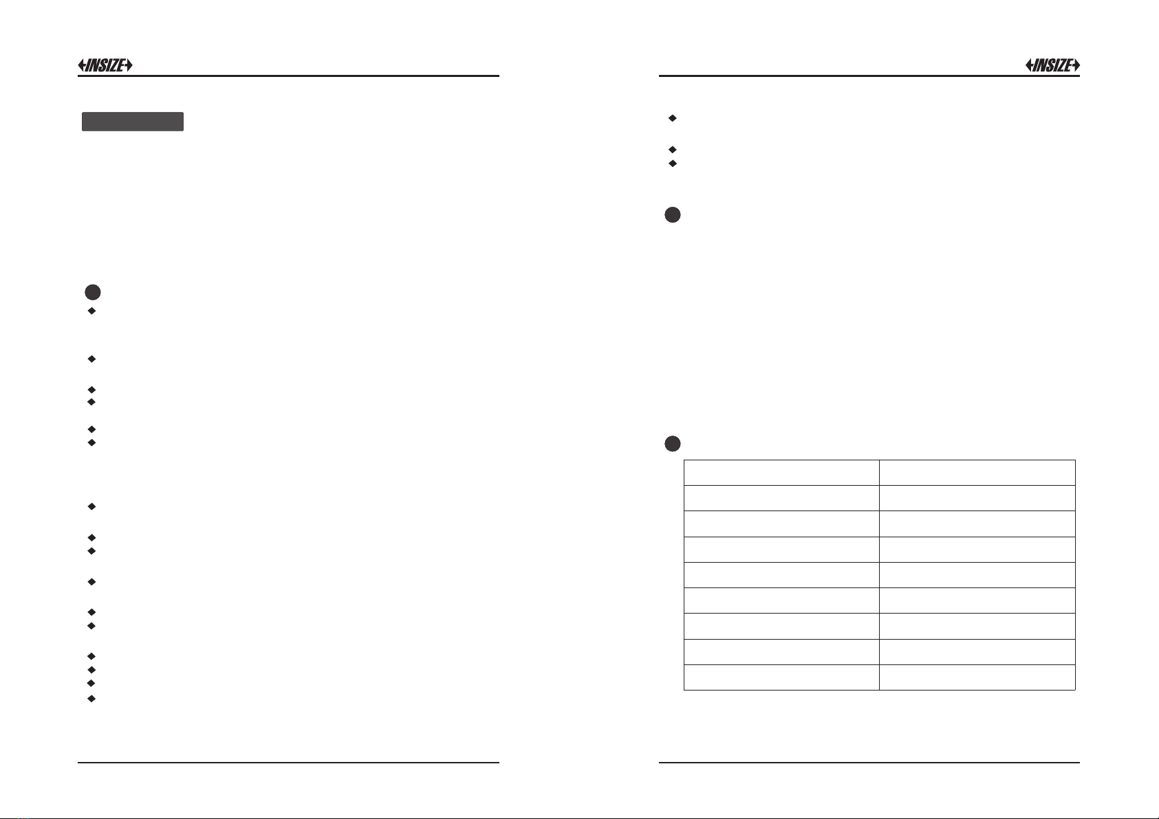
1Features
The surfaces roughness tester is a small handheld instrument, for shop
floor use and mobile measure, it operation simple, function overall,
measure fast, accuracy stability, take convenience. This tester applies to
production site and can be used to measure surface roughness of various
machinery-processed parts. This tester is capable of evaluating surface
textures with a variety of parameters according to various international
standard. The measurement results are displayed digital/graphically on the
color graphic LCD display, And output to the printer.
Composite structure of main display unit ,driver unit and Sensor.
Electromechanical integration design, small size, light weight, easy to
operation;
Data can be output to Excel by connecting with computer via bluetooth
or USB cable;
Support Bluetooth printing and mobile APP wireless operation;
Multi parameters: Ra, Rz, Rq, Rt, Rp, Rv, R3z, R3y, Rz(JIS), Rs, Rsk,
Rsm, Rku, Rc, Ry, Rmax, Rmr;
320μm Large measurement range;
The 3.5-inch color graphic LCD provides excellent readability and an
intuitive display that is easy to negotiate. The LCD of 480*320 dot
matrix includes a adjustable backlight for improved visibility in dark
environments. Wide angle of view;
DSP chip control and data processing, high speed, low power
consumption;
Display full information, intuitive and graphical displays all parameters;
The tester Complies with the following standards:ISO-1997, DIN, ANSI,
JIS2001;
Built-in 3200mAh lithium-ion rechargeable battery and control circuit,
high capacity, no memory effect;
Can work more than 50 hours while the power is enough;
Large capacity data storage, can store 100 item of raw data and
measured profile;
Real-time clock setting and display for easy data recording and storage
With automatic sleep, automatic shutdown power-saving features;
Reliable circuit and software design of prevent the motor stuck;
Instrument can display a variety of information tips and instructions. For
example Measurement result display, the menu prompts and error
messages;
Introduction Metal case design for driver unit, rugged, compact, portable, high
reliability;
Can connected to the computer and printer;
All parameters can be printed or print any of the parameters which set
by the user;
2Measurement principle
When measuring roughness of part surface, the pickup is placed on
the surface of the part and
then tracing the surface at constant rate. The pickup acquires the
surface roughness by the sharp stylus in pickup. The roughness
causes displacement of pickup which results in change of inductive
value of induction coils thus generate analogue signal which is in
proportion to surface roughness at output end of phase-sensitive
rectifier. This signal enters data collection system after amplification
and level conversion. After that, those collected data are processed
with digital filtering and parameter calculation by DSP chip and the
measuring result can be read on LCD, printed through printer and
communicated with PC.
2
3Standard Configuration
Item
Standard probe
Calibration block and support
Connecting cable
Magnetic stand adapter
Adjustable stand
Touch pen
USBcableandsoftware
AC/DC adapter
1pc
1pc
1pc of each
1pc of each
1pc
1pc
1pc
1pc
1pc
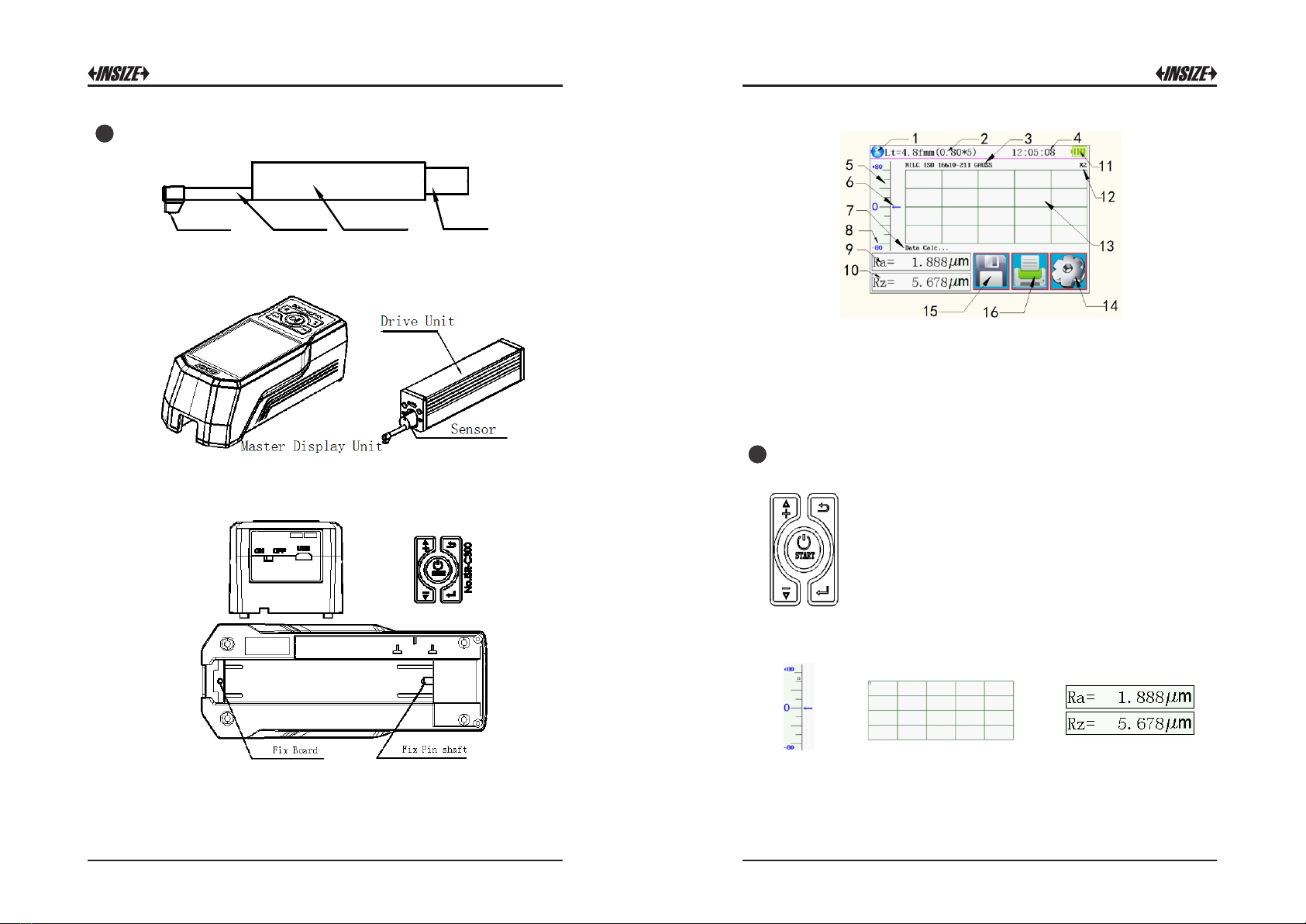
4Name of each part
Sensor
3
4
{┱〈┆■┧ Tube Sensor body Socket
Front view
Back view
Power switch is a total power switch on the instrument.
Turned off when not in use for a long time.
1 Bluetooth Mark;2 Assess length;3 Filter;4 Working Time;
5 Start Touch key area;6 Pickup position;7 Hint information area;
8 Range;9 Master results display;10 Slave results display;
11 Battery level;12 Profile scale;13 Profile display area;
14 Menu touch key;15 Save touch key;16 Print touch key
5Buttons define
Power key: Press and hold START 2 seconds On/Off tester
Start measurement key: Start the instrument to measuring
Up /Add key: Increase the value
Cancel / Exit key: Used to exit the menu and unset
Enter key: Confirmation setting
Down / decrease key: decreased the value
touch key of Hidden
Start touch key Profile zoom touch key Multi results and
Profile touch key
56
When battery voltage is too low (that is, battery voltage symbol display
on screen to prompt low voltage), the instrument should be
charged as soon as possible. USB port of the instrument for charging.
You can use the built-in power adapter for charging, you can also use
computer's USB port for charging. If use the other power adapter for
charging, the output voltage should be 5V DC , the current should be
greater than 1000mA.
Instrument displays charging animation when charging after full
animation ends, the display is full of symbols. Charging time of 5
hours.
This instrument adopts lithium ion chargeable battery without memory
effect and charging can be fulfilled at any time without affecting normal
operation of the instrument.
6Battery Charging
6
6
6
6
6
6
6
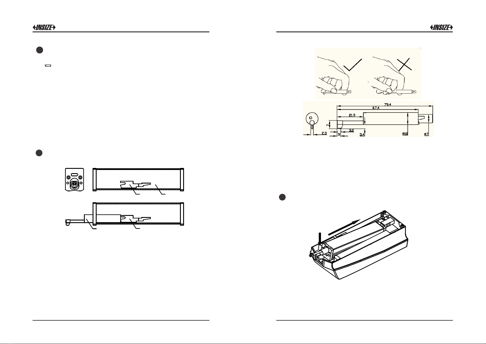
7Connection method of sensor and drive unit
When installing and remove sensors, turn off the power first.
a 2
2 3
1 sensor 2 Socket of drive unit 3 Drive unit
For installation, hold the main body of sensor with hand, push it into
socket at the the drive unit as shown in Figure and then slightly pushed
it to the end of the sheath. To remove, hold the main body of sensor or
the root of protective sheath with hand and slowly pull it out.
1. Sensor is key part of this tester and great attention.should be paid to
it.
2. During installation and remove, the stylus of sensor should not be
touched in order to avoid damage and affecting measurement.
3. Connection of sensor should be reliable during installation.
4. The sensor doesn't need to be removed when not in use.
5. Calibration is recommended after each new sensor is installed.
8Connection method of Drive unit and Main Display unit
a
2
Installation method
1 The driver unit is embedded into the main display unit according to
the direction of arrow 1, so that it is installed on the fixed pin shaft.
2 Press the drive unit in the direction of arrow 1 and down the direction
of arrow 2 to install the driver unit on the fixed plate.

7
8
Remove method
a
2
3
1 Press the driver unit toward arrow 1 and lift it toward arrow 2.
Remove the driver unit from the fixed plate.
2 Pull the driver unit in the direction of arrow 3 and take out the drive
unit.
9Extension cable usage
If the drive unit is not installed on the main display unit, please connect
the main display unit and the drive unit with the extension cable as
shown in the following figure before using it.
1 Preparation for Measurement
Switch-on to check if battery voltage is normal;
Clear the surface of part to be measured;
Place the instrument correctly, stably and reliably on the surface to be
measured;
Trace of the pickup must be vertical to the direction of process line of
the measured surface.
Measuring Operation
2Turning On/Off
Press the POWER key to hold 2 seconds after the instrument will
automatically boot, boot will display type, name and manufacturer
information, and then enter the basic measurement status main display
interface.
In any state, press the POWER key to hold 2 seconds after the
instrument will be turned off.
Introductions:
1. The next boot will be displayed when the last shutdown set content.
2. Startup and shutdown, press and hold the key for about 2 seconds to
open the instrument will perform the appropriate action.
3. Long time not to use, the instrument should be on the side of the
power switch turned off.
3Pickup Position
First, view pickup position to determine the location of the sensor. The
best location is in the middle position of the range.
Arrow indicates if it is not at zero point. The instrument can also be
measured normally.
As long as the entire measurement process does not exceed the set
range, it will not affect the measurement results.

9
10
4Start measurement
In the main interface display mode,
Press the Start key or Start key touch area to start measuring.
The measurement can be stopped according to ESC.
5Measurement result display
After the measurement, if you need to look at all the measurement
results, touch the main and secondary display area will be able to see
all the calculation results. The touch profile display area will zoom the
profile by 1-2-4-8.
More results touch area Zoom key touch area
The instrument can be connected to the printer. The measurement
results will be printed. After measurement, Press key to print the
measured data to a serial printer.
The instrument can set the print output according to the actual
requirements of arbitrary parameters choose to print or print all the
parameters, how to set the parameters, refer to "Print Settings".
6Print measurement results
6
7Storage measurement results
In the main display interface mode, press the key to save the
measurement results stored in the instrument memory. Instrument built-
in large capacity memory, can store 100 groups of raw data and profile
data.
Data storage recording date and time the file name automatically
generated according to the last data record is always stored the
most recent recording time, the last data record stored recording
record number will be 001.
8Setting Main Menu
In the main display interface mode, press the key enter main menu

11
12
9System Setting
Touch system setting area can page up system settings.
1.Master results display and slave results display
2.BPS rate setting
The BPS rate of communication between instrument and printer or
between instrument and APP of mobile phone.
Default BPS rate 115.2K
3.Auto shutdown
Set to ON instrument for 600 seconds without operation will be
automatically shutdown . When OFF is set, it will work all the time.
4.Bluetooth mode
There are 2 mode to operate Bluetooth module, print mode and
data transmission mode.
Set it to print when Bluetooth printing is needed and to Ctrl when
communicating with mobile APP
Bluetooth switch can only be operated when Bluetooth power is off.
5.Bluetooth Power
Please set the Bluetooth mode first, then turn ON the Bluetooth
power, the instrument will automatically set the Bluetooth module
as required.
Because of the unnecessary battery capacity loss caused by the
long-term opening of the Bluetooth function, the instrument will turn
off the Bluetooth power after each boot. If you need to use
Bluetooth function, please open it yourself.
6.Touch Screen calibration
When the instrument is manufactured, the touch screen has been
calibrated. Generally, calibration is no longer required, but the
physical parameters will change over time. If you find that the
button is not correct, please calibrate again. Please follow the
screen prompts.

13
14
7.Rpc Details settings
According to user's demand, Rpc-parameter's calculation can be
selected from "μm" and "%".
8.Date and Time settings
If you want to change the date and time, please press STOP first,
after the modification is finished, press START.
9.LCD Display brightness settings
10.Reset factory settings
11.Format memory
Data formatting is the deletion of data records. Once formatted, all
data will be emptied. Before the data formatting, the instrument has
the confirmation prompt information. After the user confirms, the
data will not be restored. Please proceed with caution.
Format memory takes about 1 minutes, please do not turn off
the power.
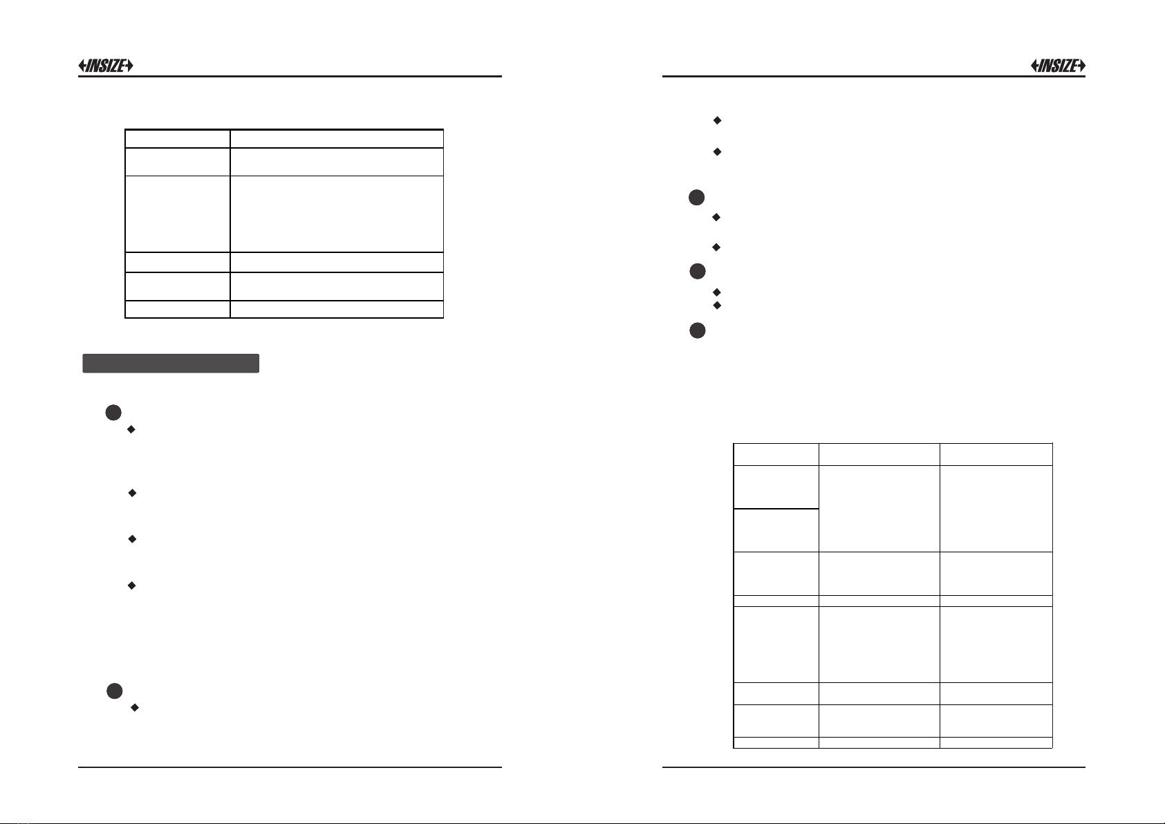
10 Measuring Condition Settings
Cut off length λc
0.25mm;0.80mm;2.50mm
Number of Sampling lengths
(×n)
1-5
Range
±20μm; ±40μm; ±80μm; ±160μm
Unit
Inchmm
Filter
RC;PC-RC;GUASS;D -P

15
16
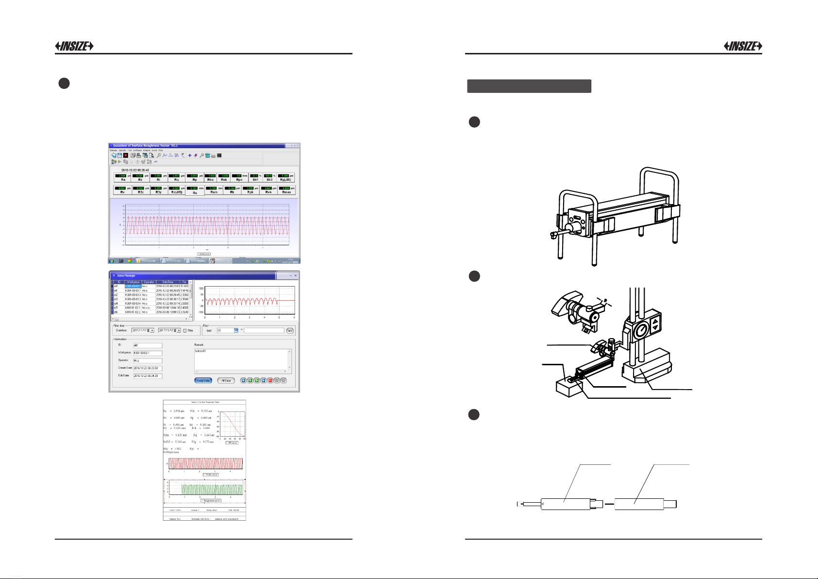
11 Record Management
Click on the corresponding record to see the details of the record.
12 Software Information
Instruments software and hardware information can help users easily
upgrade and maintain the product, unique serial number of the
instrument software information items are displayed.
13 Parameter calibration
Before measuring, the instrument usually required calibration on
standard calibration block. The instrument is configured with a standard
calibration block, before measurement, instruments should test on the
block. Under normal circumstances, when the difference between the
measured value and the block value is in the acceptable range, the
measurement value is valid, can be measured directly.
If the measured value and the block value which difference is greater
than a accuracy error range of the instrument, or the user require high
accuracy, can be used to correct the indication calibration function and
improve measurement accuracy. The value of the calibration procedure
is as shown.
Illustration is based on a model calibrated 1.63μm steps to calibrate the
model for the actual calibration of the nominal value of the set value.
1. Under normal circumstances, the instrument in the factory have been
rigorously tested, showing error is much less than ± 10%, in this case,
the user is not showing the value of the calibration frequently used
functions.
2. After setting the calibration value, you must press the START key for
a full measurement, instrument calibration to be valid.
3. New parameters after calibration must be carried out once a
complete measurement and press the Save&Exit key is stored in the
instrument.
4. Press "Exit"key to return the menu without saving calibration results.
14 Print Function setup
The instrument can be tested according to the actual requirements of
any parameter selection Print or Print All, the steps shown in Figure.

17
18
و ﮭ ى%
6.5%
5.1%
4.1%
20%
15%
10%
5%
10 0%
C( Rt)
10 0%
Rm r0Rm r
C( Rt)
Rq= 1691よm
Rz= 4.2 75よm
Ra= 1.5 98よm
** ***** ** ***** ***** *** **
Su rface R oughn ess T est er
** ***** ** ***** ***** *** **
20 13.04 .1 8 11:05 :08
Ln = 0. 8mmX5
Ra nge = 40um
Fi lter = GA USS
Ra = 1. 598um
Rz = 4. 275um
Rq = 1. 691um
Rt = 5. 113um
Rp = 1. 966um
Rv = 2. 309um
Rs = 0. 08mm
R3 z = 3 .853u m
R3 y = 4 .059u m
Rz JIS = 3.90 1um
Rs k = - 0.16
Rk u = 1 .18
Rs m = 0 .08mm
10 0% Rm r0
10 0% C(Rt)
C( Rt) Rmr
1 0% 7. 2%
2 0% 41. 8%
3 0% 49. 8%
4 0% 52. 1%
5 0% 54. 2%
6 0% 55. 9%
7 0% 58. 6%
8 0% 66. 5%
9 0% 96. 6%
15 Data output to Excel
Data can be output to Excel by connecting with computer via bluetooth.
set up Communication port, baud rate, data bit, parity check, stop bit,
traffic control and other data.
1. The roughness meter is set to print mode, the baud rate is set to
115.2k, and bluetooth pairing is turned on Connect the instrument to
the computer via bluetooth receiver.
2. Inset bluetooth receiver receiver to the computer , When the green
light shows two flashes at the interval, the pairing is successful, the
data can be directly transmitted to Excel by press “Enter” key .
16 Mobile APP
This instrument supports the wireless Bluetooth function, such as in the
high altitude or pipeline operation is inconvenient to directly operate the
instrument keys, Bluetooth remote operation function can be used.
This mobile phone APP currently supports Android version 6 or more.
Use mobile phone APP to control the instrument, please set the
Bluetooth mode to data transmission mode, and turn on the Bluetooth
power ,the connection password is 1234, It can be used when connect
with mobile phone via bluetooth.
Note: please note that the parameters of "result" is selected in "print
details set", otherwise there will be no data output to Excel
19
20
17 Dataview of software
Dataview of software can easily be waveform analysis and print
measurement results uploaded to the PC machine.
Use USB cable to connect computer data processing software to set
the tester baud rate 921.6 k.
1Adjustable height support feet
When the measured surface of the workpiece is smaller than the bases
of the instrument, the adjustable height support feet can be used as an
auxiliary support to complete the measurement.
2Height gauge adapter
Options and Usage
a∞…┧■┣∞∏ └Ⅶ─∞Ⅷ┱
Height gauge adapte
Protecting Nosepiece
Drive unit Height Gauge
3Extension rod (50mm)
Extension rod increases the depth for pickup to enter the part. Length
of extending rod is 50mm.
9ŝĊś■ŕ ╜■┼ w◘ŕ
Sensor
21 22
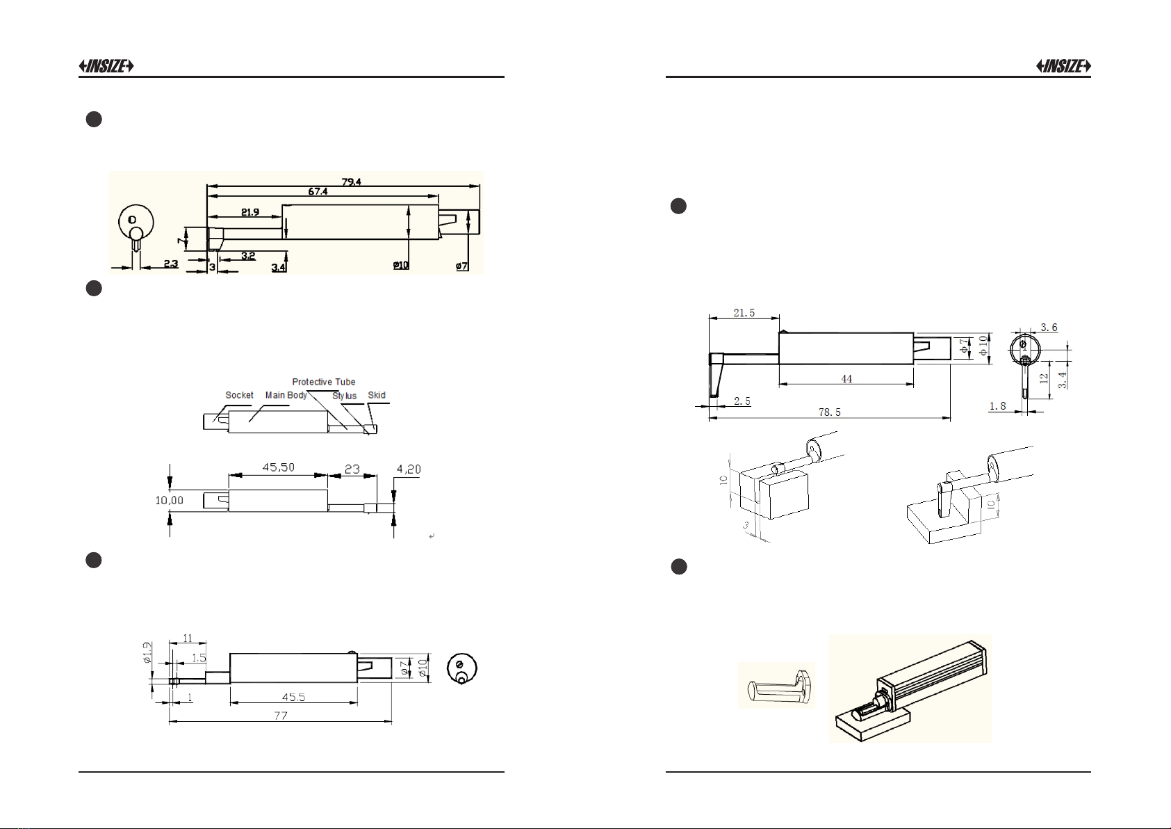
4Groove Sensor
5Small hole Sensor
The groove sensor is the standard sensor of the roughness meter, and
its demension are as follows:
Small hole sensor can measure the plane, inclined plane, cone surface,
inner hole and other surface roughness.
Minimum measurable hole diameter:Ф5mm
The use of small hole sensors must be installed on the measuring
stand for measurement.
6Extra small hole sensor
Using Extra small hole sensor, the inner surfaces of holes with radius
more than 2.5mm can be measured. Refer to the following Figure for
detailed dimension.
Extra small hole sensor operation method
The skid of the extra small hole sensor is behind the stylus. When it
contacts the workpiece, the pickup position is first high and then low.
The use of extra small hole sensors must be installed on the measuring
stand for measurement.
With deep groove sensor, it is possible to measure groove with width
wider than 3mm and depth deeper than 10mm, or the surface
roughness of step with height less than 10mm, Also can used to
measure the planar, cylindrical used with platform. please see figure for
detailed dimension.
7Deep Groove Sensor
8Support for flat surface
It is suitable for measuring the roughness of the measured object which
is smaller than the roughness tester and the measuring plane is plane.
The support can protect the sensor effectively.

23 24
9Support for cylindrical surface
It is suitable for measuring the roughness of cylindrical object which
can not be measured directly. The nosepiece can protect the sensor
effectively.
Technical Parameter and Features
10 Bluetooth printer
The printer is a Bluetooth interface, , and the roughness meter needs
to be matched with the wave, the specific rate is set to 115.2k, and the
bluetooth mode is set to "print" mode and turn on the bluetooth, the BT
indicator lights up when the roughness instrument is connected
successfully.
Note: in all of the above different measurement methods, it is
necessary to ensure that the probe has a certain downforce.The touch
pointer on the screen shall not prevail. The visual probe shall be
parallel to the object under test.
Name
Content
Measurement
Range
The Z axis
(vertical)
320μm (-160μm~160μm) / 12600よin (-6300よin~+6300よin)
The X axis
(horizontal)
17.5mm/ 0.69"
Resolution
The Z axis
(vertical)
0.002μm/±20μm
0.004μm/±40μm
0.008μm/±80μm
0.02μm/±160μm
Measurement
item
Evaluation
Parameter
Ra Rz Rq Rt Rc Rp Rv R3z R3y Rz(JIS) Ry
Rs Rsk Rku Rmax Rsm Rmr RPc Rk Rpk Rvk
Mr1Mr2
Standard
ISO4287,ANSI b46.1,DIN4768,JISb601
Graphic
Primary profile, Roughness profile, load curves
LCD dimensions
3.5-inch 480*320
Filter
RC,PC-RC,Gauss,D-P
The sampling length (lr)
0.25,0.8,2.5mm
Assessment length (ln)
Ln= lr×n n=1~5
Sensor
Principle
The displacement differential inductance
Stylus tip
Natural Diamond, 90 cone angle, 5μm tip radius
Measuring force
4mN
Skid force
Less than 400mN
Skid
RubyLongitudinal radius 40mm
Measuring speed
lr=0.25, Vt=0.135mm/s
lr=0.8, Vt=0. 5mm/s
lr=2. 5, Vt=1mm/s
Return Vt=1mm/s
Accuracy
No more than±10%
Repeatability
No more than 6%
Power supply
Built-in 3.7VLithium ion batteryCharger :DC5V,800mA/5hour
Working Time
More than 50 hours
SIZE
L×W×H
Display unit
158×55×52mm
Drive unit
115×23×27mm
Mass
About 500g(Display Unit + Dirve Unit + Sensor)
working Environment
Temperature- 20 ~ 40
Humidity< 90% RH
Store and Transportation
Temperature- 40 ~ 60
Humidity< 90% RH
25 26
Measuring Range
Param eter
M easuring range
Ra
Rq
0.005μm ~ 32μm
Rz
R3z
R y
Rt
Rp
Rm
0.02μm ~ 320μm
Sk
0 ~ 100%
S
Sm
1m m
tp
0 ~ 100%
General Maintenance
probe
Any time swap probes are to be especially careful, careful not to
touch the guide head and a stylus, because this is a key part of the
whole instrument, to try to hold the probe guide head bracket roots
(the front of the body) plug.
To complete the measurement work, please timely probe into the
box;
3. Please pay attention to protect the needle part measuring probe.
The probe's precision components, any knock, touch, fall off
phenomenon may damage the probe, should try to avoid such
situations.
The probe is a damageable parts, do not belong to the scope of
warranty parts, only provide repair. In order not to affect the
measurement work, users are advised to buy backup probe used
for emergency.
1
Main Unit
The instrument is a precision measuring instrument, should
always be handled with care, to avoid the shock.
Pay attention to add oil to maintain regularly every year to
prevent internal wear.
Battery
Always observe the battery prompt, when the low voltage,
please charge.
The charging time is 3 hours, try not to long time charge.
Standard Sample Plate
The surface of a standard sample plate must be kept clean.
To avoid scratches on the surface of sample area.
Troubleshooting
When the tester breaks down, handle the troubles according to
measures described on Fault Information. If troubles still exist,
please return the instrument to factory for repair. Users should not
dismantle and repair the device by themselves. Returned
instrument should be accompanied with sample plate attached.
Phenomenon of problem should be explained.
2
3
4
5
Error message
Cause
Solutions method
After the boot, the
display interface is
about 1 minutes,
turn off.
The cable plug is not tight.
Re insert socket
The sound of the
motor can not be
heard after turning
on the tester.
Touch screen failure
Touch Parameter loss
touch screen calibration
In the main display
interface, press ESC key for
6 seconds.
Motor error
Motor stuck
Reboot
Out of Range
1. The measured surface
signal exceeding the
measurement range
2. Placed away from the
center of the stylus position
Increase Measuring range
Adjust the Stylus position
No test data
After the boot does not
measure.
The actual measurement:
one time
Measurement
Accuracy
Out of Range
Set the parameter error
Calibration data error
Set the parameter
measurement
Calibrate the tester
Pay attention to maintaining the Main Unit surface clean, often
with a soft dry cloth to clean its surface.

27 28
References
Terms
The instrument calculate parameters on the filter profile and the
direct profile , all calculated in line with the GB / T 3505-2000
"Geometrical Product Specification(GPS) —— Surface texture:
Profile method——Term,definitions and surface texture
parameters."
Terms
Filtered profile: profile signal after primary profile is filtered to
remove waviness.
D-P (direct-profile): adopt central line of Least Square Algorithm.
RC filter: analogue 2RC filter with phase difference.
PC-RC filter: RC filter with phase-correction.
Gauss filter: ISO11562.
Traversing Length
Parameters Definitions
Arithmetical Mean Deviation of Profile Ra
Ra is arithmetic mean of the absolute values of profile deviation
Z(x) from mean within sampling length.
Z1
Z2
Zi Zn
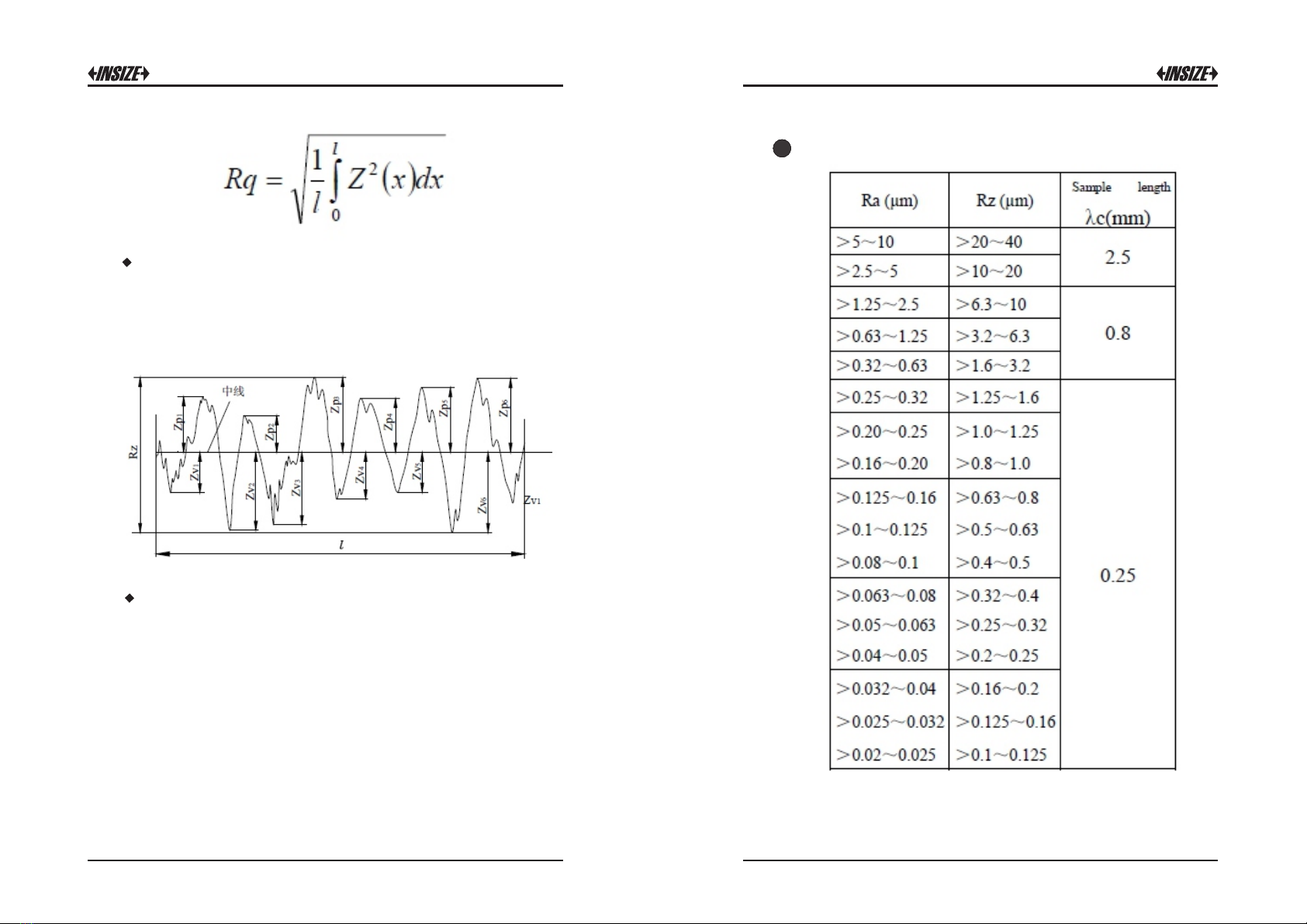
Root-mean-square Deviation of Profile Rq
Rq is the square root of the arithmetic mean of the squares of
profile deviation Z(x) from mean within sampling length.
11
12
29 30
Maximum Height of Profile Rz
Rz is The sum of height Zp of the highest profile peak from the
mean line and depth Zv of the deepest profile valley from the mean
line within sampling length。
Total Peak-to-valley Height Rt
Rt is the sum of the height of the highest peak Zp and the depth of
the deepest valley Zv over the evaluation length.
Recommended table of the sampling length
1113
Table of contents
Other insize Test Equipment manuals

insize
insize ISH-MRD200 User manual

insize
insize ISH-PHB User manual

insize
insize IST-TT Series User manual

insize
insize ISR-S300 User manual

insize
insize ISH-RD200 User manual

insize
insize IST-TT Series User manual

insize
insize ISHR-D121 User manual

insize
insize ISH-PHA User manual

insize
insize ISHR-P151 User manual

insize
insize ISHW User manual


