CheckingandsettingheadlampsNationalregulationsmustbeobserved)
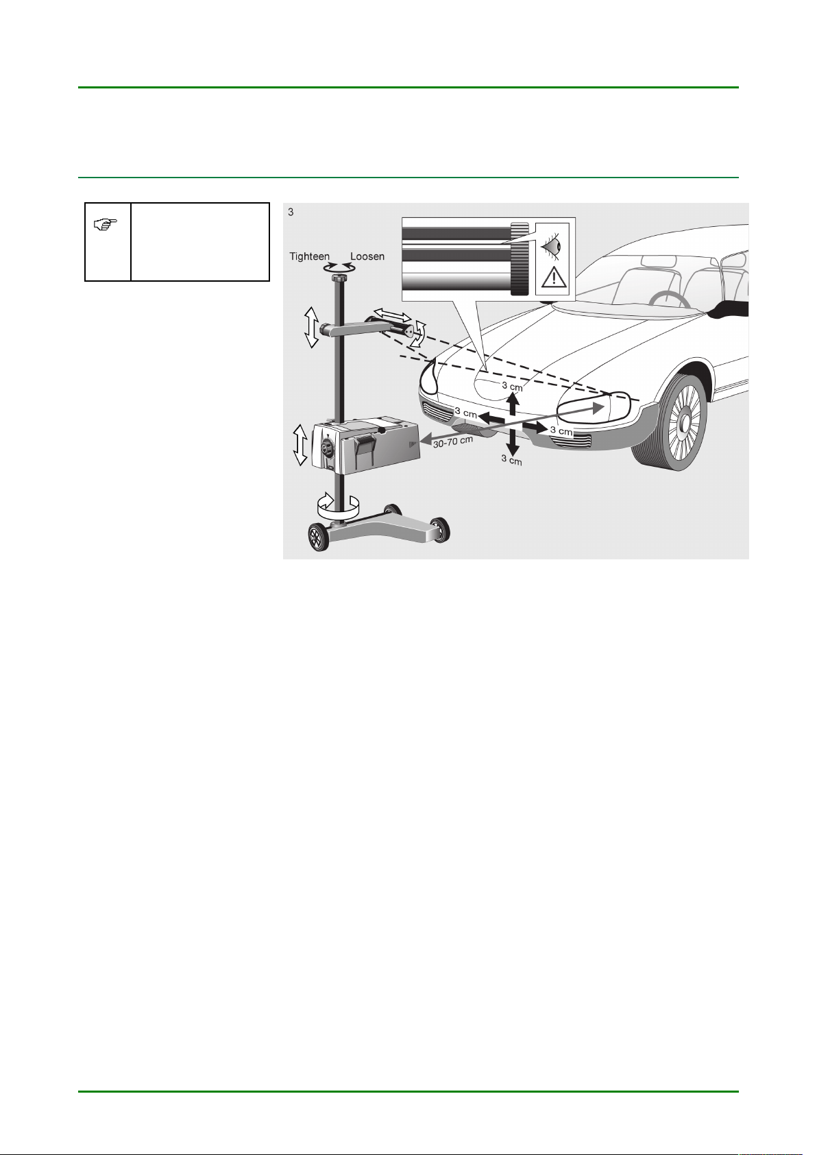
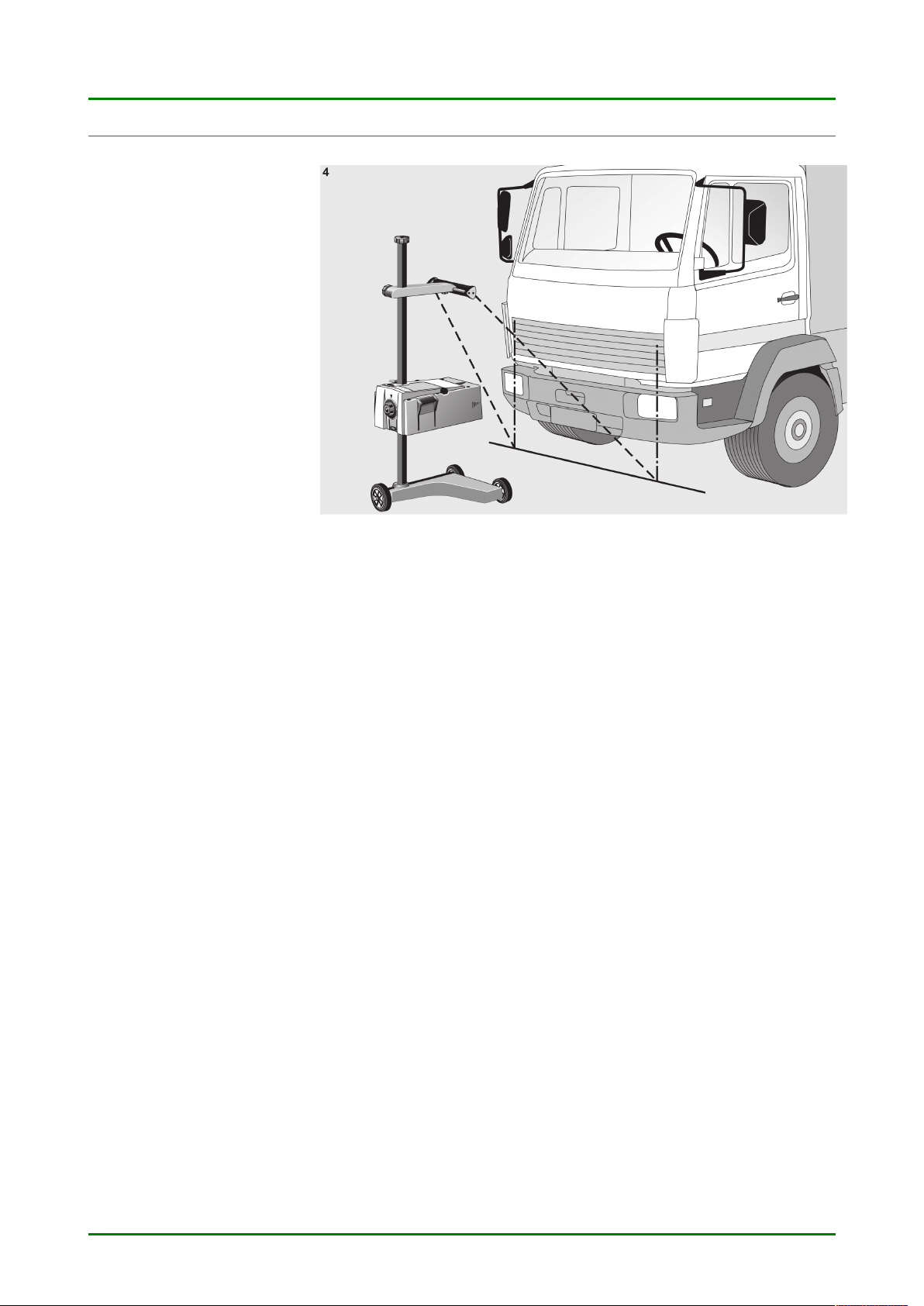
Settingup
5CheckingandsettingheadlampsNationalregulations
mustbeobserved)
NOTE
Theheadlightaimingdevicecanbeusedtoinspectallheadlightsystems,includingDE,FF,LED
andXENONheadlights.Therectangledrawnonthetestscreencorrespondstothesizeofthetest
surfacewhichismandatoryundertheDirectivefortheadjustmentofvehicleheadlamps.After
headlampshavebeenadjusted,theymustbefastenedonthevehicleinsuchawaythatitisnot
possibleforthemtobeaccidentallymovedoutofalignment.Headlampsettingsshouldbechecked
wheneverrepairshavebeencarriedouttoavehicle’ssuspension.Thisisalsorecommended
wheneveraheadlampbulbhasbeenreplaced.
Ifthevehicleisfittedwithanautomaticmechanismtocompensateformovementsinthebodyworkorheadlamps
causedbychangesintheload,thecharacteristicsofthismechanismasdescribedinthemanufacturer’sinstructions
mustbetakenintoaccount.
Tosettheheadlamps,iftheycanbeadjustedbyhandonthisparticularvehicle,theadjustmentmechanismmustbe
intheexactprescribedpositionforthebasicsetting.
Iftheadjustmentmechanismonlyprovidesfortwopositionsfortheheadlamps,andtheexactpositionisnotspecially
marked,theprocedureisasfollows:
•Ifthelightbeamrisesasthevehicle’sloadisincreased,thesettingmustbecarriedoutwiththeadjustment
mechanisminitsendpositionandthelightbeaminitshighestposition.
•Ifthelightbeamfallsasthevehicle’sloadisincreased,thesettingmustbecarriedoutwiththeadjustment
mechanisminitsendpositionandthelightbeaminitslowestposition.
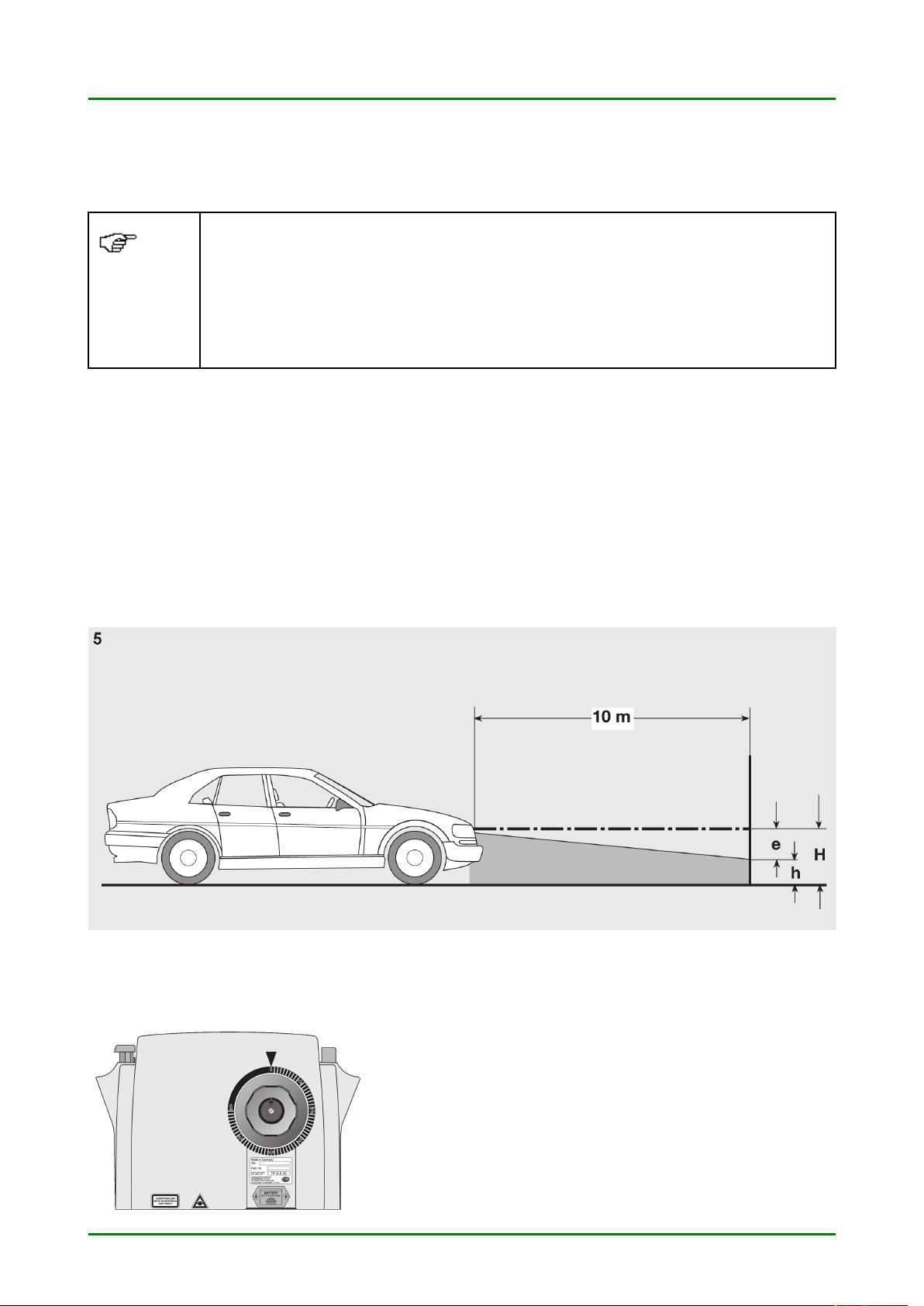
e=Distanceincmbywhichthecut-offlinemustbeinclinedatadistanceof10metres
H=Heightofthecentreoftheheadlampabovethefloor,incm
h=Heightofthedividinglineofthetestareaabovethefloor,incm.
Scaledwheel
Variousdifferentanglesofinclinationofthecut-offlineexpressedin
%areprescribedforthevarioustypesofvehilcleseeadjustment
table—cut-offlinein%x10correspondstodimension“e”)
10