EK-Team VE 600 User manual

©
Page 1 of 25
Operating Instructions
Release: June 13, 2013
EK Vario Engraver VE 600
full size (A3) / half size (A4)

Page 2 of 25
1. Introduction...................................................................................................3
2. Scope of Supply ...........................................................................................4
3. Product Overview .........................................................................................6
4. Taking into Operation....................................................................................7
5. Operation ....................................................................................................11
6. Cleaning and Care .....................................................................................16
7. Accessories ................................................................................................17
8. Fault Rectification .......................................................................................19
9. Technical Data ...........................................................................................20
10. Packing Instructions for the VE 600 ........................................................21
11. Safety Instructions ...................................................................................22
12. Contact Information ..................................................................................25
Operating Instructions
Content
EK Vario Engraver VE 600
full size (A3) / half size (A4)

Page 3 of 25
1. Introduction:
By buying the VE 600 you have acquired a flexible engraving device which will enable
you to engrave materials made from plastics, aluminum, brass and special steel,
easily and rapidly.
●Tough device structure made of aluminum profiles
●Action area dimensions 220 mm x 305 mm
●Easy exchange of fixing plates for different engraving materials
●Engraving materials in thickness of up to 2.5 mm can be worked.
Special solutions up to a height of 10 mm are also possible
●Universal voltage supply of 100-240V AC
●PC interfaces: USB connection 2.0
●Command language: HPGL
●Material fixing by means of vacuum fixing plate or adhesive mat (option)
●Firmware update for VE 600 possible by means of PC connection, and therefore via
the Internet
●Vacuum cleaner connection for suction removal of engraving chips
●Engraving depth indicator

Page 4 of 25
2. Scope of Supply for the VE 600 Engraver
When you take delivery of the engraver, please check that the consignment is
complete. Please keep the outer packing, so that the device can be transported safely
when it comes to servicing.
The scope of supply consists of the following components:
1. Vario Engraver VE 600
2. Mains power cable 3. USB data cable
4. Operating Instructions 5. Engraving spindle with
engraving needle, .5 mm, 15°

Page 5 of 25
Scope of Supply for the VE 600 engraver
6. Connection cable for engraving spindle 7. Suction hose for engraving unit
8. Connection cable for vacuum cleaner 9. Stand tube
10. Clamp for hose and engraving
spindle cable

Page 6 of 25
3. Product Overview
1) Engraving surface
2) Connection for engraving spindle
3) Connection for vacuum cleaner
4) On/Off switch
5) Fuse
6) Mains connection
7) USB connection
8) Operating panel/keypad
9) Engraving arm
10) Contact surface for zero setting of the engraving needle
11) Retaining pins for support plates
12) Engraving head
13) Engraving depth indicator
14) Mounting for cable and hose stand
2
45 6
11
Segment 1 Segment 2
11
98
12
7
1
3
10
14
13

Page 7 of 25
4. Taking the Vario Engraver VE 600 into operation
4.1 Setting up the engraver
The engraver is best set up a dry area, as free of dust as possible. Do not expose the
device to direct sunlight. Make sure that the connections are accessible at all times.
Set the VE 600 up in such a way that it stands securely and firmly on the surface
used.
Ensure that the engraving arm can move freely and is not blocked by any objects.
4.2 Connection
Connect the device by means of the mains power cable provided to a socket which
has been installed in the regulation manner. The VE 600 has a variable input AC
voltage of 100-240V~ 50-60Hz. The mains cable is exchangeable and can be adapted
to various different countries with different mains plugs.
The mains power connection is located on the
top left-hand side of the VE 600, which is where
you insert the mains cable provided.
Next to are the connections for the
vacuum cleaner and the engraving spindle.
Located at the connection point, as well as the On/Off switch, is
also the miniature fuse (4A).
Next, connect the device by means of the
USB data cable provided.
The connection point is located on the top
right-hand side of the VE 600.

Page 8 of 25
4.3 Insert the engraving spindle into the engraving head
As shown in the illustration, place the engraving spindle into the
engraving head and clamp the spindle tight with the quick-action
tightener. The engraving spindle is already fitted with an
engraving needle.
Note: Make sure the connection of the engraving spindle is
pointing towards the lever.
Caution:
Please read and take note of the safety instructions
for operation
4.4 Fitting the cable and hose stand
Insert the aluminum tube into the mounting.
Insert the clamping element for the engraving cable and the suction
hose into the aluminum tube.
4.5 Connections at the engraving head
Place the engraving head by hand (the engraver must be switched off)
into the bottom right-hand corner.
Connect the engraving spindle cable to the spindle and
tighten the screw connection of the plug to hand tightness. Now, as
shown in the illustration, lay the cable in a loose loop and clamp it
into the clamping element of the stand. Connect the other end of
the cable to the VE 600 and likewise tighten the screw connection
to hand tightness. Now plug the suction hose onto the engraving
head and lay the hose, like the cable, in a loose loop, then clamp
the hose into the clamping element of the stand.
4.6 Vacuum cleaner connection
You have the option of using the VC 500 vacuum cleaner, which is part of the product
range, or a conventional commercial vacuum cleaner for the suction clearance of the
engraving chips.
Caution:
Under no circumstances should you work without vacuum cleaning, since
otherwise the chips will cause serious dirt contamination of the engraver

Page 9 of 25
The EK-TEAM VC 500 vacuum cleaner is characterized by its
low noise development, and can be used in sustained
operation.
Note: If you use a conventional commercial vacuum
cleaner, take care to ensure that it is not overloaded by
excessively long operation.
4.7 Connection of the VC 500 vacuum cleaners
If possible, place the vacuum cleaner on the left
next to the engraver.
Now connect the vacuum cleaner connection
cable provided with the engraver to the
vacuum cleaner and the engraver, and tighten the screw
connections to hand tightness.
Next, remove the stopper on the vacuum cleaner and insert
the vacuum cleaner hose into the vacuum cleaner.
Note: During the engraving process the vacuum cleaner
switches on automatically and switches off again when the
process has ended.
4.8 Changing the vacuum cleaner filter
Conventional commercial vacuum cleaner bags are used for the
vacuum cleaner. Replacement bags can be obtained from us or via
a retail outlet.
To change the vacuum cleaner bag, actuate the catch on the
vacuum cleaner. The cover with the suction hose and vacuum
cleaner bag will open.
Before taking the bag out of its mounting, you must take off the
suction hose. To do this, rotate the hose and draw it outwards at
the same time. Re-installation takes place in the reverse order.
4.9 Replacing or cleaning the motor filter
Once you have opened the cover as described above, you can
remove the motor protection filter. To do this, you must reach
into the chamber for the vacuum cleaner bag and take out the
motor filter. It is sufficient to clean this filter from time to time.
Replacement filters can be obtained from EK-TEAM.

Page 10 of 25
4.10 Connecting a conventional commercial vacuum cleaner
If you want to use a conventional commercial vacuum cleaner, you need appropriate
adaptations, a switchbox for adapting the electrical arrangement
and a suction hose adapter. These can be optionally obtained
from us.
Plug the switch box provided into a socket installed in the
regulation manner.
Now connect the vacuum cleaner connection
cable supplied with the engraver to the switch
box and to the VE 600 and tighten the screw
connections to hand tightness.
Connect the suction hose fitted to
the VE 600 to the adapter
provided, and plug the hand
piece of the vacuum cleaner into
the rubber sleeve.
Plug the mains cable of the vacuum cleaner into the socket of
the switch box and turn the vacuum cleaner on.
Note: During the engraving process the vacuum cleaner
switches on automatically and switches off again when the process has ended.

Page 11 of 25
5. Operation
Once you have set up the VE 600, and the power supply and the data cable are
connected, you can switch the device on.
Caution:
Before the device is switched on, please make sure that there are no obstructive
objects on the working surface of the engraver which could interfere with the free
movement of the engraving arm.
Operating panel
Switching the vacuum
cleaner on and off
Changing the rotational
speed of the engraving
spindle
Failure with the
engraving spindle
Delete transferred
data from the PC Interruption or
breaking off the
engraving activity
5.1 Switching the VE 600 on and off
Turn the device on or off using the mains switch. When the device is switched on, the
engraving arm moves into the upper right-hand corner of the processing area, and
carries out auto-calibration. The green display lights up when the device is switched
on. The device is now ready for operation and can receive data from the PC.
All settings and actions are carried out via the operating panel.
VE 600 ready for
operation
Standardising the
engraving needle
zero setting
Changing the engraving
speed
Engraving spindle in
operation
Vacuum cleaner in
operation
Changing the penetration
speed
Page 12 of 25
5.2 Stop button
If the Stop button is actuated during a current job, the job will immediately be
interrupted and the engraving head will move into the upper right-hand corner of the
device. The red display indicates the interruption. When the button is actuated again,
the engraving arm will be calibrated and the job continued. The red display will go out.
5.3 Delete data memory with Clear Buffer button
If there are data present in the VE 600, this will be indicated by the yellow display
lighting up. You can delete these data by using the Clear buffer button. To do this, the
device must be in Stop mode (red display illuminated).
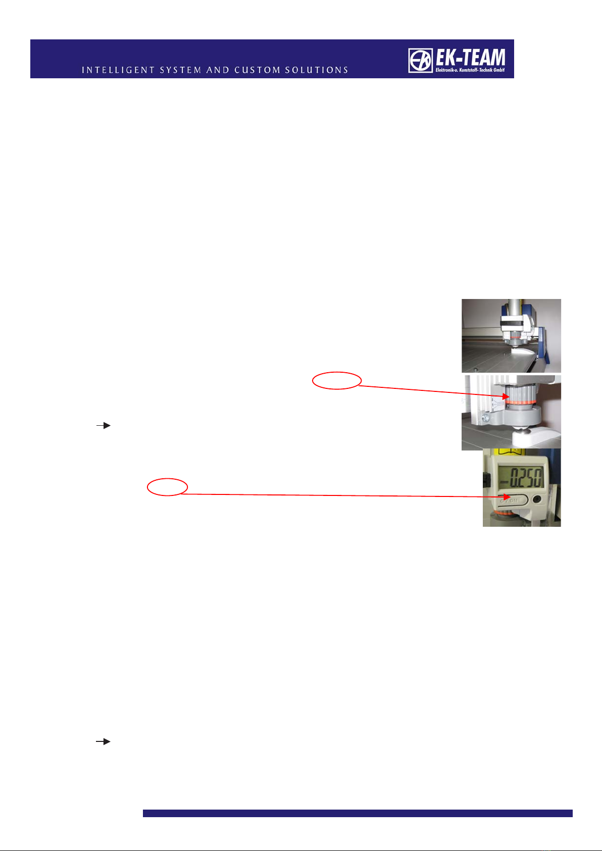
5.4 Norm button (standardisation of the engraving needle, zero setting)
If the Norm button is actuated, the engraving head will move to the
position (bottom right of the device) beneath which a contact
surface is located, and the engraving head will be lowered slowly.
As soon as the engraving needle reaches the contact surface, the
lowering of the engraving head will stop and an audible
signal will be issued. Now turn the depth adjuster to the left until the
audible signal stops.
This sets the engraving needle to the “zero position.”
Note: If there is no audible signal when the engraving head is
lowered, turn the depth adjuster to the right until the signal does
sound. Then turn it by one latch engagement position to the left.
The signal will go out and the “zero position” is set.
Press the button in order to zero the nos. of the indicator.
5.5 HIGH / LOW rotational speed of engraving spindle
When engraving data are transferred from the PC to the engraver, the
rotational speed of the engraving spindle will also be automatically transferred. If you
want to change these data during the engraving process, you can change the speed
by means of the appropriate buttons.
Actuation of the HIGH button will increase the engraving spindle speed 5000 rpm
(revolutions per minute), and actuation of the LOW button will reduce it by 5000 rpm.
5.6 HIGH / LOW engraving speed
When engraving data are transferred from the PC to the engraver, the engraving
speed will also be automatically transferred. If you want to change these data during
the engraving process, you can change the speed by means of the appropriate
buttons.
By actuating the HIGH button, the engraving speed will be increased by
2 mm/sec., and by actuating the LOW button it is reduced by 2 mm/sec.
Note: The adoption of the speed change takes place with a slight delay.

Page 13 of 25
5.7 HIGH / LOW penetration speed
When engraving data are transferred from the PC to the engraver, the penetration
speed will also be automatically transferred. If you want to change these data during
the engraving process, you can change the speed by means of the appropriate
buttons.
By actuating the HIGH button, the penetration speed will be increased by 2 mm/sec.,
and by actuating the LOW button it is reduced by 2 mm/sec.
Note: The adoption of the speed change takes place with a slight delay.
5.8 Placing support plates for fixing the engraving materials
There are a number of different support plates optionally available for fixing the
engraving material. Place the support plate being used over the retaining pins on the
engraving unit.
1) Universal support plate DIN A4/A3 (adhesion mat)
The universal support plate is suitable for materials up to
dimensions of 400x300 mm. The thickness of the material must not
exceed 2.5 mm.
The adhesion mat secures the engraving material against sliding.
2) Universal support plate DIN A4 with vacuum connection
The universal support plate is suitable for materials up to
dimensions of 200x300 mm. The thickness of the material must not
exceed 2.5 mm. The support plate has a vacuum connection
to which you can connect an in-house vacuum line.
As an option, we can offer a vacuum pump or a converter
which produces a vacuum out of compressed air
(see Accessories).
3) 3-fold Universal support plate
You can process three engraving plates on this support plate, up to
dimensions of 90x100 mm. Material thickness up to 2.5 mm.
4) 4-fold Universal support plate
You can process four engraving plates on this support plate, up to
dimensions of 60x100 mm. Material thickness up to 2.5 mm.
5) 9-fold Universal support plate
You can process nine engraving plates on this support plate, up to
dimensions of 30x100 mm. Material thickness up to 2.5 mm.
Page 14 of 25
5.9 Adjusting the engraving depth
The engraving depth is determined by means of the depth adjuster on the engraving
spindle. Different script widths for the engraving are attained as a function of the width
and grinding angle of the engraving needle used, as well as the penetration depth into
the material.
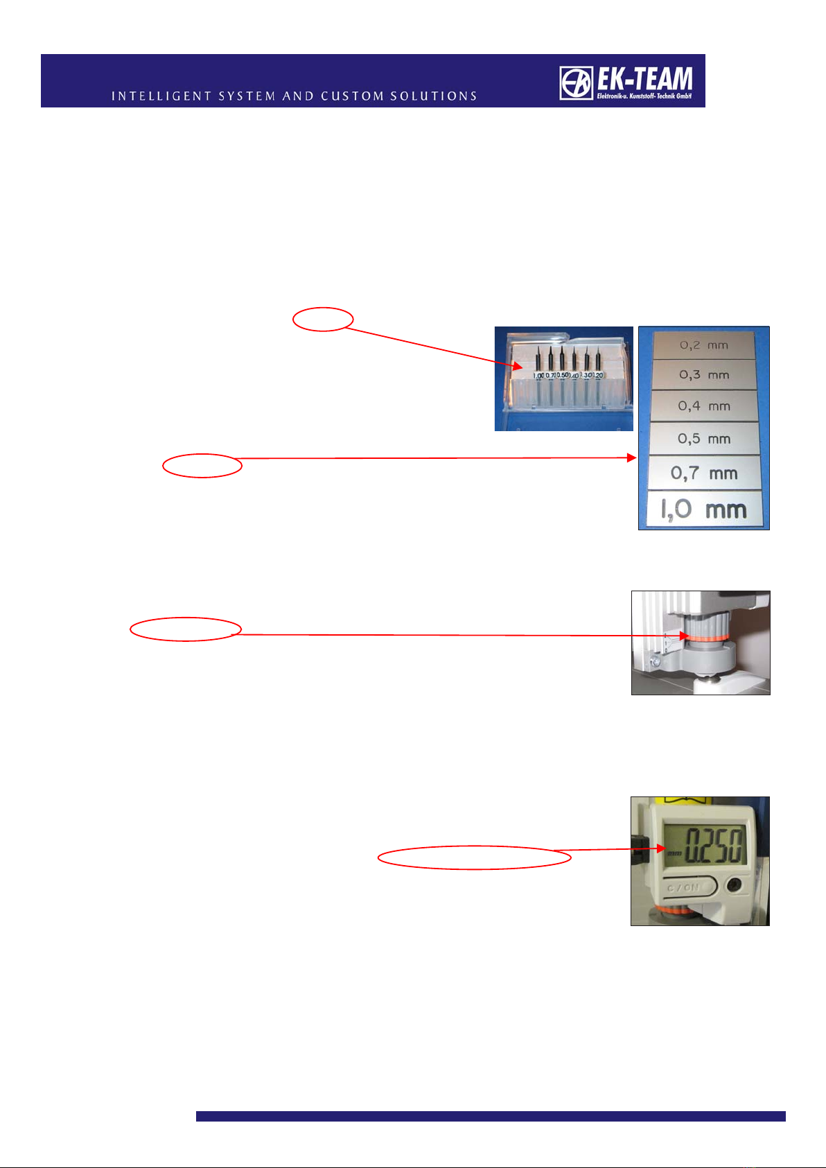
For normal use we recommend the use of engraving needles with a grinding angle
of 15°.
These are available in widths of 0.2; 0.3; 0.4;
0.5; 0.7; 1.0 mm.
Special shapes are available on request.
The examples shown will give you an idea of
the different results of the engravings.
5.9.1 Engraving depth indicator
The setting of the engraving depth is carried out by rotating the
depth adjuster. By turning it to the right, the depth of the engraving
is increased, and by turning it to the left it is reduced.
When you actuate the depth adjuster, you will feel
a latching engagement.
With each engagement, the engraving needle is set higher or lower by 0.05 mm. Once
you have turned the adjuster by one revolution to the right, you will have
reached an engraving depth of 1 mm
(20 latch engagements of 0.05 mm each).
You can read off the depth on the engraving depth indicator on the
left next to the engraving spindle.
Caution: The tips of the engraving needle are highly sensitive and must be
treated very carefully. Avoid damaging the tips. If they are damaged, the quality
of the lettering will be severely impaired.

Page 15 of 25
5.10 Changing the engraving needle
To change the engraving needle, proceed as follows: Release the securing
arrangement on the engraving
head and take out the
engraving spindle.
The connection cable does not
need to be detached. Now
rotate the depth adjuster away from the engraving spindle.
Caution: The engraving needle and the spindle may have
become hot due to operation.
Next, you must release the clamping jaws by using
the rotary knob at the end of the spindle. To do this,
push the knob in and turn it to
the left.
The jaws will now be open and
you can remove the
engraving needle.
Caution: Only release the clamping jaws just enough to allow the engraving
needle to be removed. The clamping jaws should only be opened completely for
cleaning purposes.
In order to ensure the correct length of the engraving needle, only use
engraving needles supplied exclusively by EK-TEAM with the identification ring.
We cannot undertake any guarantee for script quality or damage to the units if
other makes are used.
Caution: The tips of the engraving needles are highly sensitive and must be
treated very carefully. Avoid damaging the tips. If they are
damaged, the quality of the lettering will be severely impaired.
Slide the engraving needle into the clamping jaws as far as the
identification ring, and then tighten it up again.
Now rotate the depth adjuster onto the engraving spindle again,
until the tip of the engraving needle is still not quite projecting
(finger or material test).
Now put the engraving spindle back into the engraving head and tighten the clamping
block again with the quick-action clamping device.
For the zero setting of the engraving needle, now actuate the Norm switch and
proceed as described under 5.4.

Page 16 of 25
6. Cleaning and Care
Protect the VE 600 from dust and other dirt contamination.
Cover it over when it is not in use.
Wipe the device with a duster occasionally after use, either dry or moistened with a
mild cleaning agent.
Caution:
Never use aggressive cleaning agents to clean the Vario Engraver VE 600.
Never oil the mechanical parts of your engraver.
6.1 Handling the engraving spindle
The engraving spindle is a sensitive unit and should be treated extremely carefully.
Please use the spindle in dust-free areas only. An excessive dust burden will lead to
the sensitive bearings becoming clogged with dust, and then wearing out rapidly.
Never use compressed air to clean the spindles, because that will remove the
lubricant from the ball bearings. Do not use any lubricants when engraving. Never
clean the engraving spindle with water.
If, despite this, dust particles do appear in the clamping jaws, this may be indicated,
for example, by unclean engraving. In this case, remove the
engraving needle and rotate the jaws out with the aid of the rotary
knob. Wipe out the front part of the jaw seat with a
clean cotton swab (Q-tip), (see illustration).

Page 17 of 25
7. Accessories
Description Part no. Illustration
Engraving needle 15° - .2 mm 3501 0003
Engraving needle 15° - .3 mm
Engraving needle 15° - .4 mm
3501 0002
3501 0001
Engraving needle 15° - .5 mm
Engraving needle 15° - .7 mm
Engraving needle 15° - 1.0 mm
Engraving needle 15° - Set of .2; .3; .4; .5; .7; 1.0
3501 0000
3501 0004
3501 0005
3501 0006
Engraving needle 36° - .2 mm
Engraving needle 36° - .3 mm
Engraving needle 36° - .4 mm
Engraving needle 36° - .5 mm
3501 0015
3501 0016
3501 0017
3501 0018
Engraving needle 36° - .7 mm
Engraving needle 36° - 1.0 mm
Engraving needle 36° - Set of .2; .3; .4; .5; .7; 1.0
Engraving needle 60° - .2 mm
3501 0019
3501 0020
3501 0021
Engraving needle 60° - .3 mm
Engraving needle 60° - .4 mm
Engraving needle 60° - .5 mm
Engraving needle 60° - .7 mm
3501 0022
3501 0023
3501 0024
3501 0025
Engraving needle 60° - 1.0 mm
Engraving needle 60° - Set of .2; .3; .4; .5; .7; 1.0
Engraving needle 90° - .2 mm
Engraving needle 90° - .3 mm
3501 0026
3501 0027
3501 0028
Engraving needle 90° - .4 mm
Engraving needle 90° - .5 mm
Engraving needle 90° - .7 mm
Engraving needle 90° - 1.0 mm
3501 0029
3501 0010
3501 0011
3501 0012
Engraving needle 90° - Set of .2; .3; .4; .5; .7; 1.0
Engraving needle 35° - .2 mm
Engraving needle 35° - .4 mm
3501 0013
3501 0014
Double tooth cutter fishtail .50 mm
Double tooth cutter fishtail .60 mm
Double tooth cutter fishtail .80 mm
3501 0030
3501 0031
3501 0032
Double tooth cutter fishtail 1.00 mm
Double tooth cutter fishtail 1.20 mm
Double tooth cutter fishtail 1.40 mm
Double tooth cutter fishtail 1.60 mm
3501 0033
3501 0034
3501 0035
3501 0036
Double tooth cutter fishtail 2.00 mm
Double tooth cutter fishtail 2.40 mm
Double tooth cutter fishtail 3.00 mm
Double tooth cutter fishtail - Set of .50; .60;
3501 0037
3501 0038
3501 0039
.80; 1.00; 1.20; 1.40; 1.60; 2.00; 2.40; 3.00

Page 18 of 25
Description Part no. Illustration
Universal support plate
for Engraving and Plotting 3490 2106
half size
(
DIN A4
)
Engraving material please call for details
full size DIN A3/ half size DIN A4
blank sheet or pre-sized tags
Universal support plate 3490 2156
for Engraving and Plotting
half size
(
DIN A4
)
Vacuum
Vacuum cleaner bags (5 bags) 3502 0000
Adapter set to connect with 3400 0057
standard vacuum cleaners
Converter compressed air to vacuum 3491 0012
Vacuum pump for vacuum support plates 3491 0011
Universal support plate 3490 2117
90x100 mm
Universal support plate 3490 2116
60x100 mm
Universal support plate 3490 2115
30x100 mm
Optical measurement tool 3400 0058
Engraving for VE 600
VC 500 Vacuum cleaner 3400 0056

Page 19 of 25
8. Fault Rectification
VE 600 engraver cannot be
switched on.
The green “Power” LED
is not lighting
up.
The red LED is illuminated on
the VE 600,
“Spindle fault“.
Caution:
Engraving unit interrupts the
en
g
ravin
g p
rocess.
Check whether the mains power connection cable is connected.
Check whether the socket being used is in good order.
Check whether the mains infeed fuse on the VE 600 is in good order.
To do this, pull out the mains cable at the infeed module and the fuse
element next to the mains switch.
See Handbook page 7
High-frequency spindle is defective or there is an overload.
To check this, actuate the buttons HIGH and LOW together on the
VE 600. This allows you to increase or reduce the rotational speed of
the spindle with the buttons. If the red fault LED lights up again, the
spindle is defective and must be replaced.
Engraving operation not
possible
Check whether the connection cable between the VE 600 and the
spindle is connected. Refer to the instructions in the script
creation software VarioSign. Has the correct output device been
selected?
Check the interface cable.
Engraving is not being carried
out cleanly. Poor script image
and/or burr formation on the
engraved characters.
Check the engraving needle. If the tip is broken off or damaged the
engraving needle must be replaced.
Check whether there are any engraving chips in the spindle head or in
the spindle clamping jaws. To do this, unscrew the depth adjuster and
take the jaws out of the spindle. Clean the depth
adjuster and the spindle clamping jaws as described in the
Cleaning and Care section, “Handling the engraving spindle”,
see page 16.
Caution: Do not use compressed air to carry out cleaning.
The desired engraving depth is
not being reached.
Next, check whether there is a sufficient distance between the depth
adjuster and the engraving material, min .5 mm to about
1 mm.
To do this, move the engraving head, with the VE 600 switched off, by
hand over the engraving material and check the distance in this way.
RemedyFault description

Page 20 of 25
9. Technical Data
Vario Engraver VE 600
x-y unit: Flatbed engraver
Maximum engraving surface: A3: 440 mm x 305 mm/17.32 inch x 12.01 inch,
A4: 220 mm x 305 mm/8.66 inch x 12.01 inch
Engraving speed: max. 20 mm/s / .79 inch/s
Interfaces: USB Level 2.0
Command language: based on HP-GL 7475A
Data buffer: 16 MB
Drive: Two-phase stepper motor
Addressable resolution: .01 mm / .0004 inch
Repetition precision: .05 mm / .002 inch
Voltage supply: 100-240V AC 50-60Hz
Input current: .7 A max.
Ambient conditions: Operation: 10°C - 35°C / 50°F - 95°F
35% - 75% rel. air humidity
Storage: -10°C - 50°C / 14°F - 122°F
10% - 90% rel. air humidity
Safety certificates: EN 60950-1
Operational reliability: EN 55022 B
EN 61000-4-2 bis 6
EN 61000-4-11
Dimensions: A3: 660 mm (A4: 440 mm)x 440 mm x 125 mm/
25.98 inch(A4: 17.32 inch)x 17.32 x 4.92 inch
Weight: A3: approx. 8,85 kg / 17.64 inch,
A4: approx. 7 kg / 15.43 inch
Engraving spindle
Rotational speed: min. 5000 RPM, max. 50.000 RPM
Torque: 6 Ncm
Frequency: 83-830 Hz
Power consumption: max. 60 W
Clamping jaws: Shaft diameter 3 mm / .12 inch;
Clamping mechanism: Head gripping
Concentricity with clamping jaws: .03 mm / .001 inch
Motor design: Three-phase AC asynchronous, brushless
Housing: Aluminum
Clamping diameter: 25 mm / .98 inch
Ball bearing type: Steel, permanent lubrication, two-fold
Cooling: Self-ventilating with integrated fan
Weight: approx. 280 g / .62 lbs
Overall length: approx. 175 mm /6.89 inch
Scope of use: Exclusively for engraving
Guaranteed bearing service life: min. 1000 hours with appropriate use
Table of contents


