EKF Diagnostics Hemo Control User manual

User Manual
Sales
EKF-diagnostic GmbH
Ebendorfer Chaussee 3
D-39179 Barleben / Magdeburg
Germany
Tel. +49 (0)39 203 7850
www.ekfdiagnostics.com 3040-9001-0247 Science made Simple
User Manual
Hemo Control
CLIA
wAIved
Hemo Control

Hemo Control
Hemoglobin Measuring System
User Manual

This document is protected by copyright. It may not be reproduced or
distributed to third parties without the prior written consent of
EKF-diagnostic GmbH.
Subject to alteration. Errors excepted.
EKF-diagnostic GmbH
Ebendorfer Chaussee 3
39179 Barleben
Germany
Phone: +49 (0) 3 92 03 / 511 - 0
Fax: +49 (0) 3 92 03 / 511 - 171
Manual revision: 3.02
Released: 05/2016
Software version: 3.00.0 and higher
Hardware version: 3.5.0 and higher

Contents
User Manual Hemo Control
1
0. Contents
0. CONTENTS .....................................................................1
1. IMPORTANT INFORMATION.........................................4
1.1 SAFETY NOTES ..............................................................4
1.2 ABBREVIATIONS.............................................................5
2. INTENDED USE ..............................................................6
3. SETTING UP....................................................................7
3.1 COMPONENTS................................................................7
3.2 OPERATION ...................................................................7
3.2.1 Setting up and initial start up...................................7
3.2.2 Switching the device on and off...............................8
3.2.3 Mains operation.......................................................9
3.2.4 Battery operation.....................................................9
4. SAMPLING ....................................................................10
4.1 HANDLING OF THE MICROCUVETTE................................10
4.2 TAKING A SAMPLE OF CAPILLARY BLOOD .......................11
4.3 TAKING A SAMPLE OF VENOUS OR ARTERIAL BLOOD.......12
5. MEASUREMENT...........................................................14
5.1 SWITCHING ON THE DEVICE ..........................................14
5.2 MEASUREMENT............................................................15
5.3 RESULT SCREEN..........................................................16
5.4 QUALITY CONTROL (QC)..............................................16
5.4.1 Self test..................................................................16
5.4.2 Control cuvette ......................................................17
5.4.3 Control solutions....................................................17
5.5 MEASURED VALUE MEMORY..........................................18
6. DEVICE MENU..............................................................19
6.1 INFORMATION ..............................................................19
6.2 CONNECT....................................................................20
6.3 DATE...........................................................................20
6.4 TIME ...........................................................................20
6.5 UNIT............................................................................20
6.6 HB LIMITS ....................................................................20
6.7 CONTRAST ..................................................................20
6.8 REGION.......................................................................20

Contents
User Manual Hemo Control
2
2
6.9 OPTIONS .....................................................................21
6.9.1 Hematocrit.............................................................21
6.9.2 Print .......................................................................21
6.9.3 Sound ....................................................................21
6.9.4 Backlight................................................................21
6.9.5 Stand By................................................................21
6.9.6 Connection ............................................................22
6.9.6.1 Broadcast.............................................................22
6.9.6.2 Protocol................................................................22
6.9.7 Maintenance..........................................................22
6.9.8 Scan Service BC ...................................................22
6.9.9 Service...................................................................22
6.10 CONTACT ....................................................................22
7. ACCESSORIES AND CONNECTIONS.........................23
7.1 DATA CABLE ................................................................23
7.2 PRINTER......................................................................23
7.3 HEMO DOCK................................................................24
7.3.1 Description.............................................................24
7.3.2 Technical parameters............................................24
8. MAINTENANCE.............................................................25
8.1 CLEANING AND DISINFECTION .......................................25
8.1.1 Mains adaptor, housing and display......................25
8.1.2 Cuvette holder .......................................................25
8.1.3 Internal optical unit.................................................26
8.2 INTEGRATED RECHARGEABLE BATTERY.........................26
8.3 DISPOSAL....................................................................27
9. TROUBLESHOOTING...................................................28
9.1 DEVICE RESET.............................................................30
10. TECHNICAL DATA ...................................................31
10.1 HEMO CONTROL PHOTOMETER ....................................31
10.2 MICROCUVETTE ...........................................................32
11. THEORETICAL PRINCIPLES...................................33
11.1 REFERENCE RANGES ...................................................33
11.2 DESCRIPTION OF THE MEASURING PROCESS..................33
11.2.1 Reaction in the microcuvette.............................33
11.2.2 Principle of photometric measurement..............33
11.3 CALIBRATION...............................................................35
11.4 CALCULATION OF HEMATOCRIT VALUE...........................35

Contents
User Manual Hemo Control
3
12. APPENDIX.................................................................36
12.1 REPLACEMENT PARTS AND CONSUMER MATERIALS........36
12.2 CONTACT ....................................................................37
12.3 SYMBOLS ....................................................................38

Important Information
User Manual Hemo Control
4
4
1. Important Information
1.1 Safety notes
It is essential that you read the following notes in order to avoid risks to
persons and damage to the device and other equipment.
EKF-diagnostic GmbH does not accept any responsibility for damage
arising from non-observance of the following notes.
! Warning !
Follow the user manual!
Each time the device is used precise knowledge of and
compliance with this user manual is required. Only use the
Hemo Control photometer for the purpose described in Section
2 on page 6.
! Danger !
Danger of fatal electric shock!
Under no circumstances should you open the mains adaptor.
There are no components inside which require servicing or
maintenance.
Never use a mechanically damaged mains adaptor, live
connections might be exposed.
Never let the mains adaptor come into contact with liquids. Note
the maintenance instructions in Section 8.1.1 on page 25.
Only use the mains adaptor plug in sockets, which have been
installed to IEC guidelines. Check whether the mains voltage
and frequency printed on the mains adaptor type label match
your mains socket.
! Warning !
Do not use in areas where there is a risk of explosion!
The device is not approved for use in areas where there is a risk
of explosion.
Keep the device away from liquids!
The device is not insulated against fluid ingress. Note the
maintenance instructions in Section 8.1 on page 25.
Only use original accessories!
Only attach accessories expressly approved for use with the
Hemo Control.

Important Information
User Manual Hemo Control
5
Allow the device to reach room temperature!
When changing from a cold into a warm environment
condensation can form inside the device. Wait for about one
hour before you connect the device to the mains or switch it on.
Do not open the device!
There are no components inside which require maintenance.
Repairs must only be performed by authorized service staff. For
further maintenance, instructions please refer to Section 8 on
page 25.
1.2 Abbreviations
QC Quality control
Hb Hemoglobin
Hct Hematocrit
DM Data Management
POCT Data Manager Software to connect the device to an electronic
information system as well as for device
configuration

Intended Use
User Manual Hemo Control
6
6
2. Intended Use
The Hemo Control measuring system is intended to be used for the
quantitative determination of hemoglobin (Hb) concentrations in human
blood. It consists of the Hemo Control photometer and Hemo_Control
Hemoglobin Microcuvettes.
Using the reagent filled microcuvette a small amount of arterial, venous
or capillary blood is taken up by capillary action. The filled microcuvette
is inserted into the Hemo Control photometer. The color produced by
chemical reaction in the microcuvette is measured and the Hb value is
displayed. The microcuvettes are intended for singular use only and
must be disposed of after their use as potentially infectious waste in
accordance with the current regulations applicable to your
establishment.
The Hemo Control photometer is intended for use in medical practices
and in clinical laboratories to assist in medical diagnostic investigations.
In addition, it can be used in emergency and intensive care units and in
medical facilities such as blood donor sessions and blood banks.
Only qualified personnel with profound skills in handling in vitro
diagnostic devices and this system should be allowed to take blood
samples and operate the Hemo Control photometer.
Setting Up
User Manual Hemo Control
7
3. Setting Up
3.1 Components
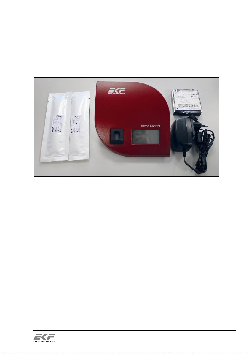
Before you set up and connect the Hemo Control, check that you have
received all components belonging to the product free of mechanical
damage.
Figure 1 - Hemo Control with mains adaptor, control cuvette and cleaner
Hemo Control photometer
Mains adaptor
Control cuvette
2 Cleaner
3.2 Operation
3.2.1 Setting up and initial start up
Select a suitable place for setting up the device and make sure to:
Avoid direct sunlight
Avoid strong electromagnetic fields
Avoid direct influence from ionizing radiation
Avoid rapid temperature variations (keep away from heaters,
open windows, ventilators, extraction or air conditioning
systems, etc.)
Operate the device in dry rooms on a flat surface

Setting Up
User Manual Hemo Control
8
8
For initial start-up connect the device to the mains. The device should
remain connected to the mains until the integrated rechargeable battery
has been fully charged.
! Warning !
The mains adaptor is designed for a mains voltage of
100 - 240 V and a frequency of 50 –60 Hz. For further
information refer to Section 10.1, Technical Data, on page 31.
For further enquiries contact your technical consultant or
distributor.
Figure 2 - Connection of mains adaptor
3.2.2 Switching the device on and off
The device is not provided with a separate switch. If the device is not
used for a longer period, it automatically switches to the energy-saving
Stand By mode. This period can be selected in the device menu; refer
to Section 6.9.5 on page 21.
The device can be switched on as follows:
Touch the display
Open or close the cuvette holder
Connect the mains adaptor to or disconnect it from the mains

Setting Up
User Manual Hemo Control
9
Please Open
Memory
Menu
15:00
3.2.3 Mains operation
The plug symbol indicates mains
operation.
An additional arrow in the battery symbol
indicates that the battery is being
charged.
Figure 3 - Mains operation
! Note !The device should remain connected to the mains until the
integrated rechargeable battery has been fully charged.
Set the mains frequency in the device menu to the correct value
of your region; refer to Section 6.8 on page 20.
(50 Hz or 60 Hz)
3.2.4 Battery operation
The battery symbol indicates its
remaining capacity. The device displays
the warning “Low battery” at low capacity.
If the battery is not recharged, the device
switches off after a while.
Figure 4 - Battery operation
In the battery mode the Hemo Control photometer can be operated for
about 100 hours. This value strongly depends on the utilization of the
device, and hence may vary.
! Note !
Continuous display backlighting is not possible under battery
operation. A temporary, energy saving lighting can be activated
in the device menu; refer to Section 6.9.4 on page 21.
Please Open
Memory
Menu
Low battery
15:00

Sampling
User Manual Hemo Control
10
10
4. Sampling
4.1 Handling of the microcuvette
Figure 5 - Microcuvette
The following rules should be observed when handling microcuvettes:
Microcuvettes are intended for singular use only.
Store the microcuvettes exclusively in their original box at room
temperature.
Remove only one microcuvette at a time from the box and close
the box immediately. The lid must be carefully closed all around.
Only use the handle and do not touch the optical eye of the
microcuvette.
The microcuvette is intended for in-vitro diagnostic use only.
Do not swallow the reagents.
Sampling
User Manual Hemo Control
11
4.2 Taking a sample of capillary blood
! Warning !
Risk of infection, please wear suitable gloves!
1. Take out a microcuvette from the supply box and close it again
tightly.
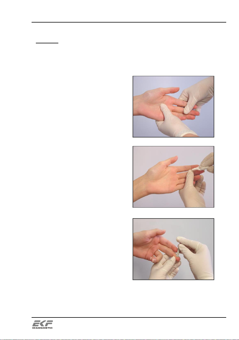
2. Lightly massage the fingers to
stimulate circulation.
Only use the middle or ring
finger. The patient should not
wear a ring on that finger.
Figure 6 - Stimulation of circulation
3. Disinfect the puncture site
and allow it to dry.
Figure7 - Disinfection
4. Press lightly on the finger tip
and puncture from the side to
a depth of about 2 mm.
Figure 8 - Puncturing of finger
Sampling
User Manual Hemo Control
12
12
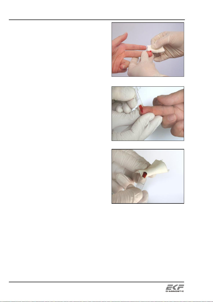
5. Blot away the first drop of
blood and press lightly again.
The second drop must be
large enough to fill the
microcuvette in one step.
Figure9 - Blotting away blood
6. Hold the tip of the
microcuvette in the middle of
the drop of blood and let the
cavity fill completely in one
step. The microcuvette must
be filled bubble-free.
Figure10 - Filling the cuvette
7. Remove any excessive blood
from the outside of the
microcuvette. Be careful to
prevent sucking out and
emptying of the microcuvette
cavity.
Figure 11 - Removing excessive blood
The microcuvette sample prepared in this way can be measured
immediately or within 10 minutes at the latest.
4.3 Taking a sample of venous or arterial blood
The Hemo Control can be used for determination of venous or arterial
blood samples if the blood was sampled not longer than 24 hours ago
and the sample material has been stored in a fridge. Prepare the sample
for the measurement as follows:

Sampling
User Manual Hemo Control
13
! Warning !
Risk of infection, please wear suitable gloves!
1. Take out the sample tube from the fridge and allow it to warm up
to room temperature. Mix the sample carefully by repeated
rotating and rolling.
2. Take out a microcuvette from the supply box and close it again
tightly.
3. Pipette a sufficiently large drop of blood (about 15 µL) on a
clean, non-absorbent material (e.g. PE film).
4. Hold the tip of the
microcuvette in the middle of
the drop of blood and let the
cavity fill completely in one
step. The microcuvette must
be filled bubble free.
Figure 12 - Filling the cuvette
5. Remove any excessive blood
from the outside of the
microcuvette.
Be careful to prevent sucking
out and emptying of the
microcuvette cavity.
Figure13 - Removing excessive blood
The microcuvette sample prepared in this way can be measured
immediately or within 10 minutes at the latest.

Measurement
User Manual Hemo Control
14
14
5. Measurement
5.1 Switching on the device
If the device is not used for a longer period, it automatically switches to
the energy saving Stand By mode.
The device can be switched on as follows:
Touch the display
Open or close the cuvette holder
Connect the mains adaptor to or disconnect it from the mains
Screen explanation
Figure 14 - Screen
Mains operation: The plug symbol indicates that the device is
under mains operation. If this symbol is not
displayed, the device is under battery operation.
Battery
operation: This symbol indicates the battery state of
charge.
Battery being
charged: An arrow in the battery symbol indicates that the
battery is being charged when connected to the
mains.
Info: Information, as may be required, is displayed
here.
Opening the cuvette holder sets the device ready for measurement.
Battery operation / Battery being charged
State
Info
Memory Button
Menu Button
Actual time
Mains operation
Low battery
Please Open
Memory
Menu
15:00

Measurement
User Manual Hemo Control
15
5.2 Measurement
Inserting the microcuvette and closing the cuvette holder starts the
measurement. Depending on the configuration, several options are
available prior to the measurement.
! Warning !
Ensure the cuvette is correctly positioned in the cuvette holder.
The microcuvette must be inserted flat. The angled handle of the
microcuvette must point to the right, see Figure 15.
Figure 15 - Correctly positioned cuvette Figure 16 - Incorrectly positioned cuvette
Figure 17 - Ready
PT: Selection of patient type. This button is only displayed if
measurement with Hb limit values is activated. This function is
activated in the Menu under item 6.6, Hb limits. If a patient type
has been selected, this type is displayed by an accordant symbol
in the PT button. (M=male, F=female, C=child)
Closing the cuvette holder starts the
measurement.
Figure 18 - Measuring
Angled handle
Angled handle
Ready
Patient Type M
15:00
Measuring
Memory
Menu
15:00

Measurement
User Manual Hemo Control
16
16
5.3 Result screen
The number of symbols displayed may
vary depending on the options selected
prior to the measurement.
Figure 19 - Patient result
(M): A patient type (male) has been selected. +or –behind the PT
signalises that the value has exceeded or fallen below the limit
value.
Hct: Approximate hematocrit value. If the option is activated in the
device menu under item 6.9.1, the hematocrit value is calculated
and displayed for measured values between 120 and 180 g/L.
Rej:A measured value can be rejected by the operator by pressing
Rej. A rejected value is marked accordingly.
R: The measured value has been rejected by the operator.
OK:Press to leave the result screen.
Showing +++ or −−− instead of a value indicates a value higher or lower
than the measurement range (see Section 10, page 31, Technical Data).
In this case, the used microcuvette and the blood sample should be
checked critically. Further it should be checked if an Adaptation is
applied (see Section 6.1, page 19, Information), which has an influence
on the displayed values.
5.4 Quality Control (QC)
EKF-diagnostic GmbH recommends regular performance of quality
control measurements, unless local laws, guidelines and orders will
demand it anyway.
5.4.1 Self test
The Hemo Control photometer has implemented an integrated algorithm
for checking the optical and electronic components of the device. This
self test is carried out automatically in regular intervals and demands no
operator action.
OK
Result
156 g/L
(M+) Hct≈46%
Rej
R

Measurement
User Manual Hemo Control
17
5.4.2 Control cuvette
The control cuvette is a physical standard for a comfortable and cheap
check of the device. We recommend measuring the control cuvette once
a day.
Store the control cuvette always in the original box. Avoid contamination
of the control cuvette with potential infectious material. Clean and
disinfect the cuvette holder and the device before using the control
cuvette (see section 8.1, page 25). Keep away humidity (air humidity
>85%) from the control cuvette. Do not clean the control cuvette with any
solutions. If necessary clean the control cuvette carefully with a dry
cotton bud.
! Warning !
Each control cuvette with indicated limit values belongs to a
specific device. Hence, do not confuse control cuvettes. If a new
control cuvette is needed, it must be ordered as a set and needs
to be calibrated to the device.
The control cuvette is measured like a normal sample, refer to Section
5.2 on page 15. Thereafter it needs to be checked, whether the result is
within the limit values indicated on the box of the control cuvette. If the
value is outside the limits refer to Section 9, Troubleshooting.
5.4.3 Control solutions
To verify the complete measuring system including the microcuvette
liquid control materials are used, which are very similar to the patient
sample. We recommend measuring the control solutions once a week.
For handling the control material refer to the respective instructions for
use. We recommend using the control material Hb-con, which is offered
in various concentrations (see Section 12.1, page 36). If you use other
control material we cannot guarantee for the accuracy of the results.
Table of contents
Other EKF Diagnostics Test Equipment manuals


