GDZX ZXHQ-A+ CT User manual

ZXHQ-A+ CT/PT
Characteristics Tester

- 1 -
Contents
Ⅰ. Introduction........................................................................................................ - 2 -
Ⅱ. Test Function..................................................................................................... - 2 -
Ⅲ. Technical Parameter........................................................................................ - 2 -
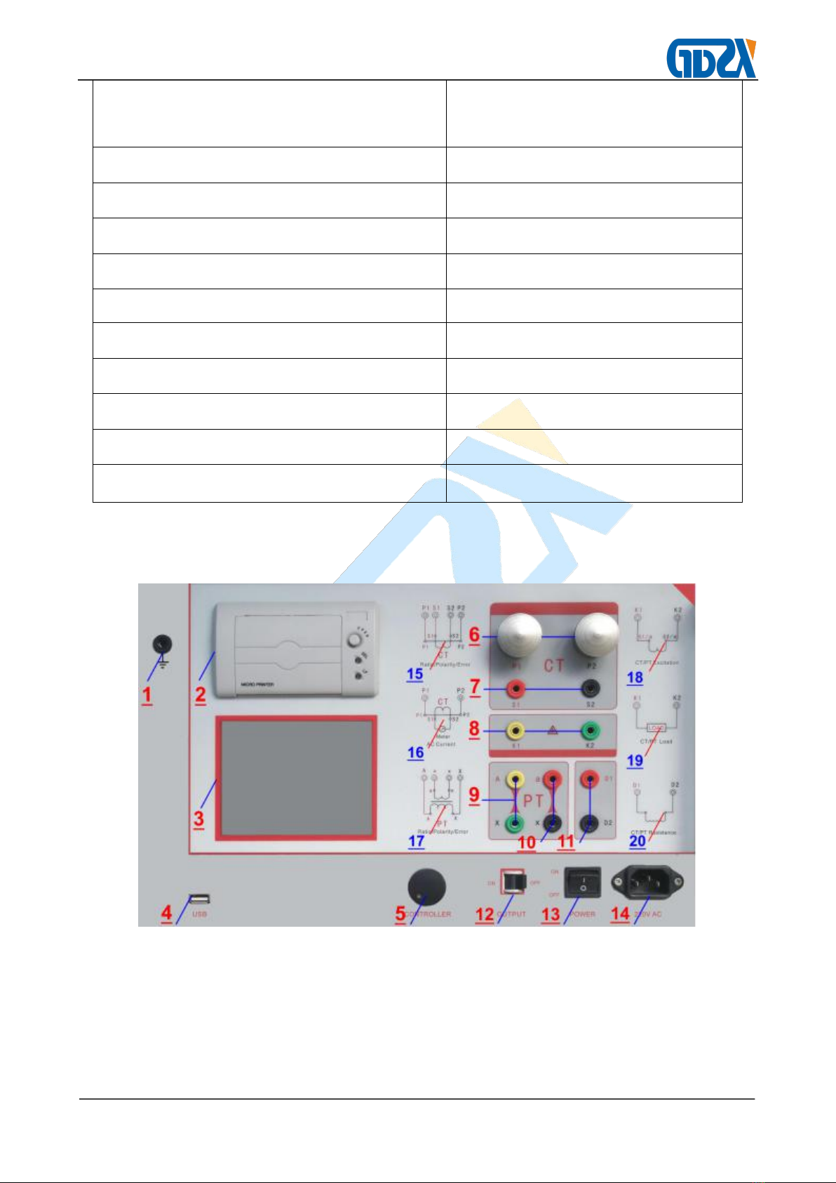
Ⅳ. Panel Introduction............................................................................................. - 3 -
Ⅴ. Operation Method............................................................................................. - 6 -
1. Controller...........................................................................................................- 6 -
2. Main Menu........................................................................................................ - 6 -
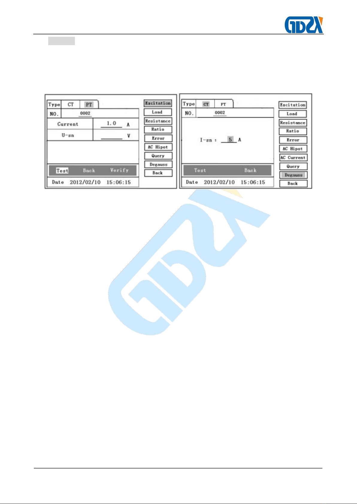
3. Excitation...........................................................................................................- 6 -
4. Degauss Test................................................................................................... - 9 -
5. AC Current:Current Output.......................................................................... - 10 -
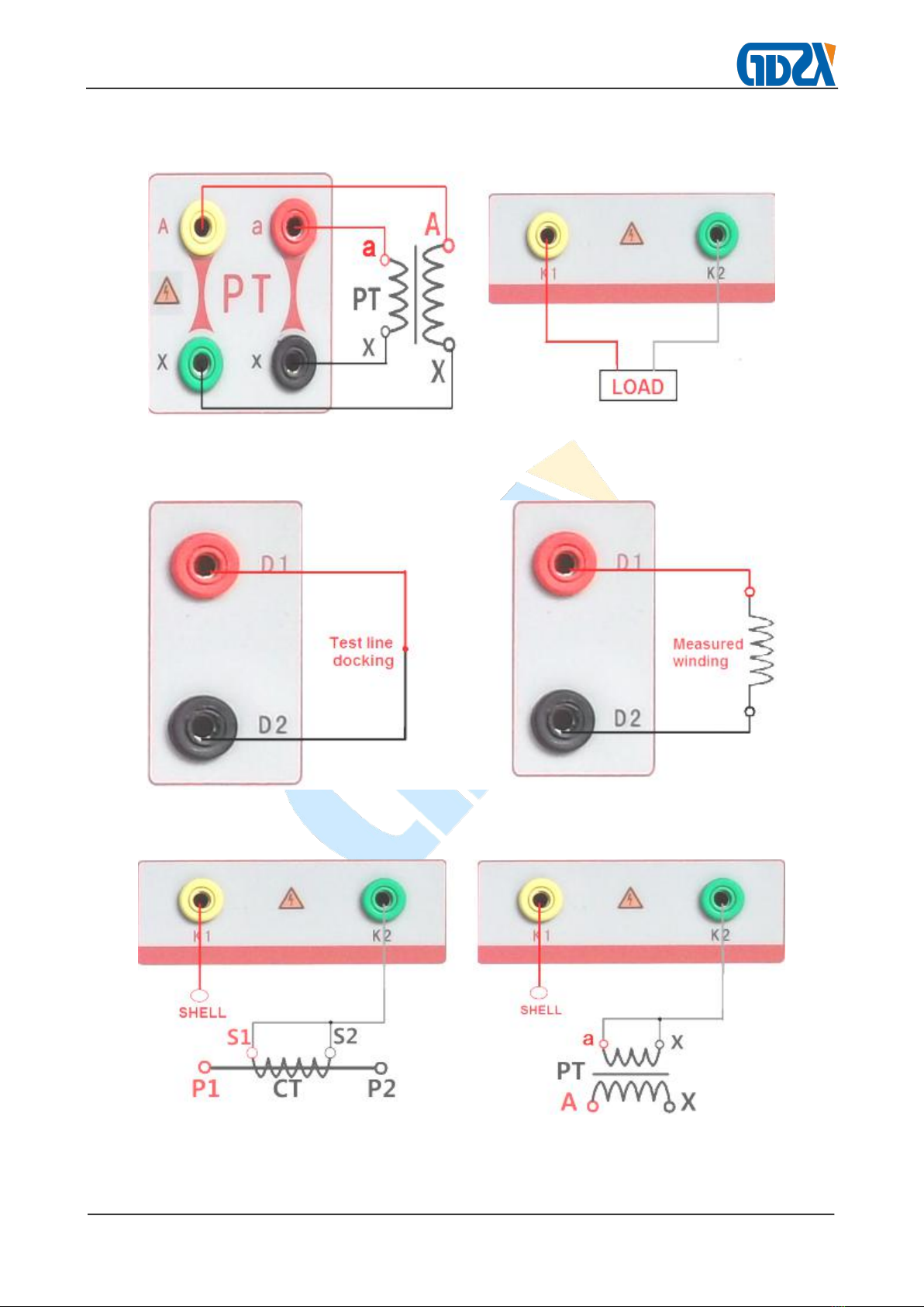
6. Ratio:Ratio and Polarity Test....................................................................- 10 -
7. Error Test........................................................................................................ - 12 -
8. Load Test........................................................................................................ - 13 -
9. Resistance Test............................................................................................. - 14 -
10. AC Hipot (Voltage Withstand Test of Alternating Current).................. - 15 -
11. Index (Query)............................................................................................... - 16 -
12. PC Software................................................................................................. - 17 -
Ⅵ. Precautions...................................................................................................... - 18 -
Ⅶ. Packing List......................................................................................................- 18 -
Appendix.................................................................................................................- 20 -

- 2 -
Ⅰ. Introduction
ZXHQ-A+ CT/PT Characteristics Tester is mainly used for field testing of P class CT
and PT. The test items mainly include excitation characteristic,transformation ratio, polarity,
Degauss,5% and 10% error curves,secondary circuit check,withstand test of power
frequency alternating current and secondary load.Adopt LCD,self-equipped minitype printer
supporting field printing;supporting to use USB flash disk to dump data,with simple and
convenient operation.
Ⅱ. Test Function
Current Transformer (CT)
Voltage Transformer (PT)
●Magnetization Curve
●Excitation Characteristic Test
●Transformation Ratio Test
●Polarity
●Polarity
●5% and 10% error curve
●Withstand Test of Power Frequency
●Current Injecting
●Degauss
●Degauss
●Calculation of Knee Point Value
●Withstand Test of Power Frequency
Alternating Current
●Actual Secondary Load Test
●Automatic Calculation of Excitation
Knee Point Value
●Resistance Test
●Actual Secondary Load Test
●Resistance Test
Ⅲ. Technical Parameter
Operational Power Supply
AC220V±20V, 50~60Hz
Equipment Power Supply Output Waveform
Sine Wave
Single Machine Output Voltage of Excitation
Characteristic
0~2500V
Excitation Output Current
0~20A

- 3 -
Ⅳ. Panel Introduction
Figure 1
Note of Panel:
1—— Grounding
2—— Printer
3—— Monitor
Single Machine Output Current of
Transformation Ratio Test
0~1000A
CT ratio measurement range
5~25000A/5A(5000A/1A)
PT ratio measurement range
1~500KV
Load Range
5~1000VA
Resistance measurement range
0.1~300Ω
Error
≤0.5%
(0.2%*Reading+0.3%*Range)
Operating Temperature
-10℃~+40℃
Relative Humidity
<90RH%
Altitude
≤1000m
Overall Dimension(Length×Width×Height)
400 *200 * 260(mm)
Weight
≤23 Kg

- 4 -
4—— USB
5—— Controller
6—— Current Output Terminal
7—— Current Input Terminal(Connected to Secondary Side for CT Transformation
Ratio Test)
8—— Excitation Characteristic Power Output/The Port of Actual Secondary Load Test
9—— Connected to Primary Side for PT Transformation Ratio Test
10 —— Connected to Secondary Side for PT Transformation Ratio Test
11 —— The Port of Resistance Test
12 —— Output (turned left for on and right for off.)
13 —— Power Switch
14 —— Power Socket
15、16、17、18、19、20 —— The wiring diagram of the test project
Figure 2 Figure 3
(CT Excitation Connection Diagram) (PT Excitation Connection Diagram)

- 5 -
Figure 4 (CT Current Figure 5(CT Connection Diagram
Output Connection Diagram) for Transformation Ratio, Polarity)
Figure 6(PT Connection Diagram Figure 7(CT/PT Actual
Transformation Ratio, Polarity) Secondary Load Connection Diagram)
Figure 8 (CT/PT Test line Figure 9(CT/PT Resistance
zero Connection Diagram) Connection Diagram)
Figure 10(CT Connection Diagram Figure 11(PT Connection Diagram
for Withstand Test of Alternating for Withstand Test of Alternating Current)

- 6 -
Ⅴ. Operation Method
1. Controller
The controller has three states: “Left Rotation”, “Right Rotation” and “Pressing down”. It is
used to move the controller, input data and select the test item.
Figure 12 (CT Main Menu) Figure 13 (PT Main Menu)
2. Main Menu
The main menu has seven items of “Excitation”、
“Load”、
“Ratio”、
“Error”、
“AC Hipot”、
“AC Current”、“Query”、“Degauss” and “Back”, which can be selected and set with
Controller.
Note: before test please set the number settings which will be saved as index information
to facilitate the user to inquire.
NO.: (0000~9999)
3. Excitation
Move the controller to Excitation For example to enter CT Test interface(Figure 14).
1) CT Excitation Characteristic Test: the connection mode is as shown in Figure 2.
Current:the setting range for output current is 0~20A (It is usually set to be 1A)
Voltage: The setting range for output voltage is 0~2500V
The function of calibration: mainly used to view the tester output voltage and current values
for the test project, Not to be used to test, The specific content to see Appendix I.
1Test
After ensuring the correct wiring, turn on the output, press the “Test” key to start the test,
After the completion of the test, the tester will automatically draw the figure of
magnetization curve(Figure 15).

- 7 -
Figure 14 Figure 15
2Excitation Characteristic Function Items (as shown in Figure 15)
All operating function items on the interface are as following:
Print: select “Print” item to print the excitation curve graphics and data.
Data: Select “Data” item and the screen will display the list of excitation characteristic
voltages and currents (shown in Figure 16). Page up and down through turning the
controller.
Save:select “Save” item to save the current test results in the memory of the equipment
and display “Saved”.
ErrCurve: as shown in the interface of Figure 15, select “ErrCurve” item and the screen
will display the setting menu for corresponding error curve(see Figure 17).
After the completion of the settings, the tester will automatically work out the error curve (as
shown in Figure 18). The specific content to see Appendix .
Return: return to the previous interface.
PrintSet:select “PrintSet” item and the screen will display the menu for the Data Set,you
can select “Custom” to setting the current value to be printed ,or select“Default” (see
Figure 19).

- 8 -
Figure 16 Figure 17
Figure 18 Figure 19
Setting of error curve
VA:CT secondary side impedance value.
I-sn:CT secondary side rating current (1A or 5A).
Kalf:As for protection type CT (5P10 20VA),“10”is Kalf
5%:Calculate the 5% error curve data and display the error curve.
10%:Calculate the 10% error curve data and display the error curve.
Error Curve Function Items
Print:print the error curve graphics and data.
Data:inquire error curve graphics and data.
Back:return to the previous menu.
2) PT Excitation Characteristic Test (with connection mode shown in Figure 3)
Move the controller to Excitation , to enter PT Test interface(Figure 20)
U-sn : 100V、100/√3V、100/3V、150V、220V.
Current : the setting range for output current is 0~20A (It is usually set to be 1A)

- 9 -
Warning: the zero terminal of primary winding of the voltage transformer shall be
grounded before the test, or high voltage will be output.
Please refer to the CT excitation characteristic test for the explanation of the operation
method and test result.
Figure 20 Figure 21
4. Degauss Test
1) CT Degauss Test (The connection mode is as shown in Figure 2.)
Parameter Setting: as shown in Figure 21,
I-sn:1A or 5A.
Move the controller to“CT”, Select Degauss to enter CT Degauss test interface (Figure
22).Select Test key to start the test. When the test is completed, the interface displays
"success",According to the actual situation, select “Test” or “Back”.
2) PT Degauss Test (See Figure 3 for connection mode)
Parameter Setting: as shown in Figure 22,
U-sn:100V、100/√3V、100/3V、150V、220V.
Move the controller to“PT”, Select Degauss to enter PT Degauss test interface (Figure
22).Select Test key to start the test. When the test is completed, the interface displays
"success",According to the actual situation, select “Test” or “Back”.

- 10 -
Figure 22 Figure 23
5. AC Current:Current Output (connection mode shown in Figure 5)
Set Currrent: 0~1000A,
Selection of output current (Figure 23): maximum output current from P1 and P2
terminals of the tester. With the changing of the operating voltage, the actual output current
will change with a deviation of 15%, which won’t affect the application. After the completion
of the setting, turn on the output, and select “Test” item. When the output current of the
equipment reaches the setting value, it will be held for a period of time (the holding time is
about 10MIN for the setting current less than 300A,between 300A and 500A the holding
time is about 2MIN, the holding time is about 3S for the setting current greater than 500A.)
During the test process, the controller will be displayed on the “Test” item and flashes
constantly unless automatically escaped when the test is completed or the test is
interrupted manually.
6. Ratio:Ratio and Polarity Test
1) CT Transformation Ratio and Polarity Test (connection mode shown in Figure 4)
Move the controller to“CT”, Select Ratio to enter CT transformation ratio test interface
(Figure 20). Connect the CT primary side to P1 and P2, and the CT secondary side to S1
and S2,
Parameter Setting: as shown in Figure 24,
I-p:Setting range of primary output current: 0~1000A.
I-s:1A or 5A.
After checking the correct wiring, Turn on the output. Move the controller to “Test” item to
start the test. With increasing of AC output to the primary side of CT, the current values

- 11 -
measured on the circuits on the primary and secondary sides will be displayed on the
screen in real time. After the test, the transformation ratio and the polarity state will be
worked out automatically.
Polarity Discrimination Method: the homochromatic terminal of the tester is in-phase
terminal, namely P1 connected to P1 of CT, and S1 connected to S1 of CT. The polarity is
“-”subtractive polarity according to the test result.
During the test process, the controller will be displayed on the “Test” item and flashes
constantly unless escaped from the automatic test interface when the test is completed or
the test is interrupted manually through pressing down controller. After the completion of
the test, select “Print”、“Save”or “Print”.
Figure 24 Figure 25
2) PT Transformation Ratio and Polarity Test (connection mode shown in Figure 6)
Parameter Setting: as shown in Figure 25,
U-p : Setting range of output voltage: 0~2500V.
U-s:100V、100/√3V、100/3V、150V、220V.
After checking the correct wiring, Turn on the output. Move the controller to start item of the
transformation ratio and polarity test menu and press down the controller to start the test.
The equipment will automatically give the transformation ratio result and polarity
state(Figure 21).
Polarity Discrimination Method: the homochromatic terminal of the tester is in-phase
terminal, namely A and a are in-phase terminals. The polarity is “-”subtractive polarity
according to the test result.
During the test process, the controller will be displayed on the “Stop” item and flashes

- 12 -
constantly unless escaped from the au tomatic test interface when the test is completed or
the test is interrupted manually through pressing down controller. After the completion of
the test, select “Print”、“Save”or “Print”.
7. Error Test
1) CT Error Test (connection mode shown in Figure 4)
Move the controller to“CT”, Select Error to enter CT Error test interface (Figure 26).
Connect the CT primary side to P1 and P2, and the CT secondary side to S1 and S2,
I-pn:Setting range of primary output current: 0~1000A.
I-sn:1A or 5A.
Rated Load:The capacity of analyzer.
Actual Load:
According to the rated load setting, automatic calculation of load and light load
of two kinds of state values (light load to full 25%).
After checking the correct wiring, Turn on the output. Move the controller to “Test” item to
start the test. With increasing of AC output to the primary side of CT, the current values
measured on the circuits on the primary and secondary sides will be displayed on the
screen in real time. After the test, the error test result will be worked out
automatically(Figure 27).
During the test process, the controller will be displayed on the “Test” item and flashes
constantly unless escaped from the automatic test interface when the test is completed or
the test is interrupted manually through pressing down controller. After the completion of
the test, select “Print”、
“Save”or “Print”. If the display is 9, then the error exceeds the display
range, please check the setting value.
Figure 26 Figure 27

- 13 -
Figure 28 Figure 29
2) PT Error Test (connection mode shown in Figure 6)
Parameter Setting: as shown in Figure 28,
U-pn: 0~2500V.
U-sn: 100V、100/√3V、100/3V、150V、220V.
Rated Load: The capacity of analyzer.
Actual Load: According to the rated load setting, automatic calculation of load and light load
of two kinds of state values (light load to full 25%).
After checking the correct wiring,Turn on the output. Move the controller to“Test”item of the
error test menu and press down the controller to start the test. The equipment will
automatically give the error result (Figure 29).
During the test process, the controller will be displayed on the “Test” item and flashes
constantly unless escaped from the au tomatic test interface when the test is completed or
the test is interrupted manually through pressing down controller. After the completion of
the test, select “Print”、
“Save”or “Print”. If the display is 9, then the error exceeds the display
range, please check the setting value.
8. Load Test
1) CT Load Test (The connection mode is as shown in Figure 7.)
Parameter Setting: as shown in Figure 30,
Line-Res:Set the resistance value of the test line.
I-sn:1A or 5A.
Move the controller to“CT”, Select Load to enter CT load test interface.Select Test key to
start the test and the test result will be displayed automatically. According to the actual

- 14 -
situation, select “Print”、“Save”or “Print”.
2) PT Load Test (See Figure 7 for connection mode)
Parameter Setting: as shown in Figure 31,
Line-Res:Set the resistance value of the test line.
U-sn:100V、100/√3V、100/3V、150V、220V.
Move the controller to“PT”, Select Load to enter CT load test interface.Select Test key to
start the test and the test result will be displayed automatically. According to the actual
situation, select “Print”、“Save”or “Print”.
Figure 30 Figure 31
9. Resistance Test
1) CT Resistance Test
Parameter Setting: as shown in Figure 32,
Move the controller to“CT”or“PT”, Select Resistance to enter CT resistance test interface
(Figure 23).The test should be preceded by a test line to zero.
Zero:One side connect to D1 and D2, Another side should to be shorted (The connection
mode is as shown in Figure 8.) and select the zero, after the end of the zero, the interface
zeroing is success.
See Figure 9 for connection mode, Select Test key to start the test and the test result will be
displayed automatically. According to the actual situation, select “Print”、“Save”、“Print”
or“Back”.
2) PT Resistance Test
The same to CT resistance test.

- 15 -
Figure 32
10. AC Hipot (Voltage Withstand Test of Alternating Current)
Move the controller to“CT”or“PT”, Select AC Hipot to enter AC Hipot test interface (Figure
33), The users can set the AC output voltage to be 0 ~2500V according to their
requirements.
Set Voltage:Voltage output range (0~2500V)
1) CT Test
The connection mode is as shown in Figure 10(CT), short circuit the secondary side S1 and
S2 and connect them to the tester voltage output terminal K2, while the other voltage
output terminal of the tester K1 is connected to the transformer shell.
move the controller to Test to increase the voltage and main it for 60S. If the flashover
phenomenon occurs in the test, then CT secondary insulation against ground is deemed to
be unqualified. If the leakage current is too much, the equipment will automatically return to
zero for protection.
Figure 33
2) PT Test

- 16 -
The connection mode is as shown in Figure11(PT), short circuit the secondary side ‘a’
and‘x’ and connect them to the tester voltage output terminal K2, while the other voltage
output terminal of the tester K1 is connected to the transformer shell.
Move the controller to Test to increase the voltage and main it for 60S. If the flashover
phenomenon occurs in the test, then CT secondary insulation against ground is deemed to
be unqualified. If the leakage current is too much, the equipment will automatically return to
zero for protection.
11. Index (Query)
1) Record Inquiry
Move the controller to“CT”or“PT”, Select Index to enter Index interface (Figure 34).
According to this interface, you can view the test results: “Excitation”、
“Load”、
“Ratio” 、
“Error” 、“Resistance”. Each piece of record will be displayed through “Number” and
“Save Date”. 8 pieces of data are displayed on each page, use controller to page up and
down.
If the user wants to inquire certain group of file, he can move controller to the files of this
group and then click it. The LCD screen will display the result.
2) Dump Data
Under the Figure 35 interface, insert the USB flash disk to the USB interface of the tester
and press down "Copy To", then the tester start dumping the data to the USB flash disk.
After that the screen will display “success”.
Warning: it is strictly forbidden to pull out the USB flash disk before the completion of the
unloading, or the USB flash disk or the equipment will be damaged permanently.
3) Delete Files
Press down “Delete”of “Excitation”、“Load” 、“Ratio”、“Error”or “Resistance”, then
all saved results can be deleted in one time.

- 17 -
Figure 34 Figure 35
12. PC Software
1) Operating ambient, WINDOWS XP and backward compatibility WINDOWS operating
system.
2) 2Function description: open host computer software Integrated Test Equipment of
Mutualinductor.
1Choose the category of mutualinductor“CT”or“PT”.
2Choose corresponding test functions. If you want to open transformation ratio and
polarity data, choose Transformation Ratio and Polarity Test option, and then click Open to
open transformation ratio and polarity data in USB disk. If you open transformation ratio
and polarity data in the interface of voltage-current characteristic test, it can not be display
correctly.
3Click Print in the interface of voltage-current characteristic to print voltage-current
characteristic curve and data. Click Print in the interface of deviation curve to print
voltage-current characteristic curve & data and deviation curve & data simultaneously.
4Click Report and import corresponding function data according to operation tips,
then report can be generated on A4 paper.

- 18 -
Figure 36
Ⅵ. Precautions
In order to ensure the safety of persons and equipment, please carefully read the
operation manual before using the tester.
The tester shall be reliably grounded when used, or persons or equipment may be
damaged.
Touching the connection terminals in the test is strictly forbidden.
The tested CT must be in offline state, or the normal application may be affected or the
test result may be incorrect.
The tester shall be operated by professional technicians.
Individually opening the equipment may lead to permanent damage.
Ⅶ. Packing List
No.
Model Name
Quantity
1
Host
1

- 19 -
2
Power Cable
1
3
Test Clamp
2
4
High Current Test Line
2
5
Test Line (Including Crocodile Clip)
2
6
Ground Wire (Including Crocodile Clips)
1
7
Fuse
5
8
Printer Paper
2
9
Manual
1
10
Test Report
1
11
Certificate / Warranty Card
1
This manual suits for next models
1
Table of contents
Other GDZX Test Equipment manuals