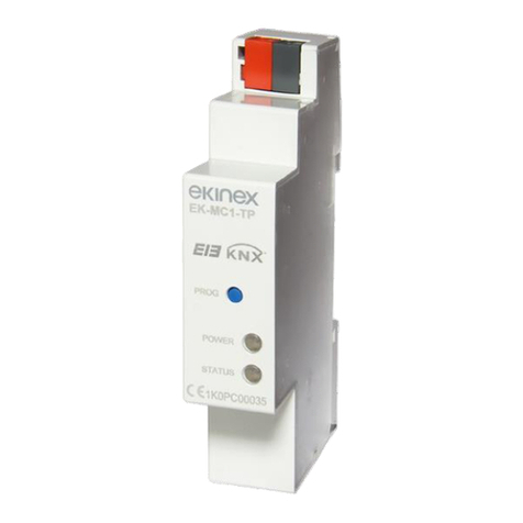
Ekinex EK-BO1-TP-RMA User manual

1
Description
The ekinex® EK-BO1-TP-RMA interface is a modular
KNX S-mode device that allows bidirectional communi-
cation between the RDZ air handling units, equipped with
control board with RS-485 Modbus communication port,
and the KNX system (TP). Thanks to the interface, the
functions performed by the air handling units can be con-
trolled and monitored by KNX devices. The unit has an
integrated KNX bus communication module and is reali-
zed for mounting on a 35 mm rail. Power is supplied via
the KNX bus.
Function
The interface represents a node on the KNX network
and performs the Master function on the Modbus net-
work to which the control board of the air handling unit
is connected as the only Slave. The interface manages
a bidirectional data ow between Modbus RTU (Remote
Terminal Unit) and KNX. The Modbus registers are read
cyclically and their value can be sent as a communication
object on the KNX bus. The data update on the KNX net-
work can take place cyclically and/or on variation event of
the data acquired by the Modbus network. The interface
acquires the value of KNX communication objects during
the exchange of telegrams on the bus. The acquired va-
lue is converted and written on the appropriate Modbus
register. The conguration is carried out by ETS by me-
ans of the corresponding application program.
RDZ supported air handling units
The interface supports RDZ air handling units for use in
residential buildings listed in the following table.
Data sheet STEKBO1TPRMA_EN
For more information on RDZ air handling units, MVHR
and dehumidication systems, please refer to the cor-
responding catalogue and technical documentation on
www.rdz.it.
Main characteristics
• Housing in plastic material
• Mounting on 35 mm rail (according to EN 60715)
• Protection degree IP20 (installed device)
• Safety class II
• Weight 70 g
• 2 modular units (1 unit = 18 mm)
• Dimensions 36 x 94 x 71 mm (WxHxD)
Technical data
Power supply
• 30 Vdc from KNX bus line
• Current consumption (from main bus line) < 13 mA
Environmental conditions
• Operating temperature: - 5 ... + 45°C
• Storage temperature: - 20 ... + 60°C
• Transport temperature: - 20 ... + 60°C
• Relative humidity: 5 - 95% not condensing
Switching, display and connection
elements
The device is equipped with 3 signalling LEDs, a terminal
for connection to the KNX bus line, a 3-pole screw termi-
nal for connection to a Modbus RTU line, a pushbutton
and a programming LED.
Switching elements
Pushbutton (B) for switching between normal operation
and programming mode
Modbus / KNX interface
for RDZ air handling units
Code: EK-BO1-TP-RMA
TP1
S
traffic
R
Error
Modbus / KNX interface for
RDZ air handling units
EK-BO1-TP-RMA
Modbus
Power
RX
TX
green
red
A B
Family Function Installation
CHR Mechanical ventilation with heat recovery Horizontal
(ceiling)
WHR Mechanical ventilation with heat recovery Verticale
(wall)
UAP PDC Air renewal with dehumidication Horizontal
(ceiling)
UC Air renewal with dehumidication Horizontal
(ceiling)
1. LED for Modbus trac
2. LED for device state
3. LED for error signalling
4. LED for KNX programming
A. Modbus terminal block
B. Programming pushbutton
C. KNX terminal block
traffic
R
Error
Modbus / KNX interface for
RDZ air handling units
EK-BO1-TP-RMA
Modbus
Power
RX
TX
green
red
A B
4
A
1
2
B
C
3

2
i
!
Display elements
• LED Modbus trac (1)
- red on: transmitting (TX)
- green on: receiving (RX)
• LED power (2)
- on: active device
- o: not active device
• LED error (3)
- on (xed): the air handling unit congured in ETS
does not correspond to the connected unit
- on (blinking): communication error on Modbus line
• LED programming KNX (4)
- display of the active mode: on = programming, o =
normal operating
Mounting
The device has degree of protection IP20, and is there-
fore suitable for use in dry interior rooms. The housing is
made for rail mounting according to EN 60715 in boards
or cabinets for electrical distribution. The installation is in
horizontal position, the correct position is when the KNX
bus terminal is located at the bottom. For the installation
of the device on the rail proceed as follows.
• with the aid of a tool bring the locking device in the
fully lowered position (a);
• place the upper edge of the rear inner prole on the
upper edge of the rail (b);
• rotate the device towards the rail (c);
• push the locking device upward until it stops (d).
b
a
c
d
Before removing the device, be sure the Modbus cable
has been disconnected and the KNX bus terminal has
been extracted from its slot. Use a screwdriver to slide
down the locking device and remove the device from the
rail.
Note. When mounting the device in boards and cabi-
nets it shall be provided the necessary ventilation so
that the temperature can be kept within the operating
range of the device.
Connection of the KNX bus line
The connection of the KNX bus line is made with the ter-
minal block (red / black) included in delivery and inserted
into the slot at the bottom of the housing.
Characteristics of the KNX terminal block
• spring clamping of conductors
• 4 seats for conductors for each polarity
• terminal suitable for KNX bus cable with single-wire
conductors and diameter between 0.6 and 0.8 mm
• recommended wire stripping approx. 5 mm
• color codication: red = + (positive) bus conductor,
black = - (negative) bus conductor
Warning! In order to supply the KNX bus lines use
only KNX bus power supplies (e.g. ekinex EK-AB1-TP
or EK-AG1-TP). The use of other power supplies can
compromise the communication and damage the devi-
ces connected to the bus.
traffic
R
Error
Modbus / KNX interface for
RDZ air handling units
EK-BO1-TP-RMA
Modbus
Power
RX
TX
green
red
A B
+
-
Bus
KNX
A
B
Modbus
RS-485

3
i
!
!
!
Connection of the KNX bus line
The connection of the KNX bus line is made with the ter-
minal block (red / black) included in delivery and inserted
into the slot at the bottom of the housing.
Characteristics of the KNX terminal block
• spring clamping of conductors
• 4 seats for conductors for each polarity
• terminal suitable for KNX bus cable with single-wire
conductors and diameter between 0.6 and 0.8 mm
• recommended wire stripping approx. 5 mm
• color codication: red = + (positive) bus conductor,
black = - (negative) bus conductor
Warning! The electrical connection of the device can
be carried out only by qualied personnel. The incor-
rect installation may result in electric shock or re.
Before making the electrical connections, make sure
the power supply has been turned o.
Conguration and commissioning
Conguration and commissioning of the device require
the use of the ETS® (Engineering Tool Software) program
V4 or later releases. These activities must be carried out
according to the design of the building automation system
done by a qualied planner.
Note. The conguration and commissioning of KNX
devices require specialized skills.To acquire these
skills, you should attend the workshops at KNX certi-
ed training centers.
Conguration
For the conguration of the device parameters the corre-
sponding application program or the whole ekinex® pro-
duct database must be loaded in the ETS program. For
detailed information on conguration options, refer to the
application manual of the device available on the website
www.ekinex.com.
Code Application program
(## = version)
EK-BO1-TP-RMA APEKBO1RMATP##.knxprod
Commissioning
For commissioning the device the following activities are
required:
• make the electrical connections as described above;
• turn on the bus power supply;
• switch the device operation to the programming mode
• by pressing the programming pushbutton located on
the front side of the housing. In this mode of operation,
the programming LED is turned on;
• download into the device the physical address and the
conguration with the ETS® program.
At the end of the download the operation of the device
automatically returns to normal mode; in this mode the
programming LED is turned o. Now the bus device is
programmed and ready for use.
Reset of the device
To reset the device remove the bus connection by ex-
tracting the bus terminal from its seat. Keeping pressed
the programming pushbutton, reinsert the bus terminal in
his seat; the programming LED blinks fast. Release the
programming button and remove the bus terminal again;
the reset was carried out. Now you need to address and
congure again the device via ETS.
Warning! The reset restores the device back to the
state of delivery from the factory. The address and
the value of the parameters set during con guration
will be lost.
Marks
• KNX
• CE: the device complies with the Low Voltage Directi-
ve (2014/35/UE) and the Electromagnetic Compatibility
Directive (2014/30/UE)
Maintenance
The device is maintenance-free. To clean use a dry cloth.
It must be avoided the use of solvents or other aggressive
substances.
Disposal
At the end of its useful life the product described in this da-
tasheet is classied as waste from electronic equipment
in accordance with the European Directive 2012/19/UE
(WEEE), and cannot be disposed together with the muni-
cipal undierentiated solid waste.
Warnings
• Installation, electrical connection, conguration and
commissioning of the device can only be carried out
by qualied personnel in compliance with the appli-
cable technical standards and laws of the respective
countries
• Opening the housing of the device causes the imme-
diate end of the warranty period
• In case of tampering, the compliance with the essen-
tial requirements of the applicable directives, for which
the device has been certied, is no longer guaranteed
• ekinex®KNX defective devices must be returned to the
manufacturer at the following address: Ekinex S.p.A.
Via Novara 37, I-28010 Vaprio d’Agogna (NO)
Other information
• The instruction sheet must be delivered to the end
customer with the project documentation
• For further information on the product, please contact
the ekinex®technical support at the e-mail address:
com
• KNX®and ETS®are registered trademarks of KNX
Association cvba, Brussels
© Ekinex S.p.A. 2020. The company reserves the right to make chan-
ges to this documentation without notice.
Warning! Incorrect disposal of this product may cau-
se serious damage to the environment and human
health. Please be informed about the correct disposal
procedures for waste collecting and processing provi-
ded by local authorities.
Other Ekinex Control Unit manuals
Popular Control Unit manuals by other brands

oventrop
oventrop Cocon 2TZ Installation and operating instructions

turck
turck TBPN-L1-FDIO1-2IOL user manual

Honeywell
Honeywell L5000-Wi-Fi installation guide

Graco
Graco Compact Dyna-Star 25P686 instructions

Data Translation
Data Translation DT9847 Series user manual

ICP DAS USA
ICP DAS USA MDC-700 Series quick start

Optimus
Optimus AV-4 Installation and operating instructions

SEW-Eurodrive
SEW-Eurodrive MOVITRAC LT Series operating instructions

Allen-Bradley
Allen-Bradley 1785-KE user manual

i3-TECHNOLOGIES
i3-TECHNOLOGIES iMO-LEARN - MDM user manual

ESBE
ESBE CRA110 series manual

Isenberg
Isenberg TVH.4501 installation manual