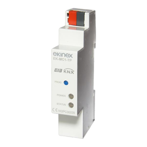
Ekinex EK-FE1-TP Instructions for use

Application manual
KNX binary output module
EK-FE1-TP 4/8-channel
EK-FF1-TP 8/16-channel

Application manual
KNX binary output modules EK-FE1-TP / EK-FF1-TP
Release 2.1 - Update: 10/2018 MAEKFE1FF1TP_EN
© EKINEX S.p.A. - All rights reserved Page 2
Contents
1Scope of the document.............................................................................................................................. 5
2Product description.................................................................................................................................... 6
3Switching, display and connection elements............................................................................................. 7
4Configuration ............................................................................................................................................. 8
5Commissioning .......................................................................................................................................... 8
6Function description................................................................................................................................... 9
6.1 Startup .................................................................................................................................................. 9
6.2 Offline operation.................................................................................................................................... 9
6.2.1 Operation with bus supply only..................................................................................................... 9
6.2.2 Operation with auxiliary supply only.............................................................................................. 9
6.2.3 Output restore ............................................................................................................................... 9
6.3 Manual operation ................................................................................................................................ 10
6.3.1 Status of the outputs across modes............................................................................................ 10
6.3.2 Activation of manual mode.......................................................................................................... 11
6.4 Online operation.................................................................................................................................. 12
6.4.1 Software working cycle ............................................................................................................... 12
6.4.2 State variables (Communication objects) ................................................................................... 12
6.4.3 Output independent mode and coupling..................................................................................... 12
6.4.4 Output features in independent mode......................................................................................... 13
6.4.4.1 Relay inversion....................................................................................................................... 14
6.4.4.2 Feedback ............................................................................................................................... 14
6.4.4.3 Time delay.............................................................................................................................. 14
6.4.4.4 Staircase function................................................................................................................... 15
6.4.4.5 Logic function......................................................................................................................... 19
6.4.4.6 Lock function.......................................................................................................................... 22
6.4.4.7 Forcing function...................................................................................................................... 23
6.4.4.8 Scene management............................................................................................................... 24
6.4.4.9 Operating hours / Energy consumption counter .................................................................... 25
6.4.4.10 Output restore values............................................................................................................. 25
6.4.5 Output features in coupled mode................................................................................................ 27
6.4.5.1 Coupled output control basics................................................................................................ 28
6.4.5.2 Valve control .......................................................................................................................... 29
6.4.5.3 Shutter control........................................................................................................................ 29
6.4.5.4 Venetian blind control ............................................................................................................ 30
6.4.5.5 Lock function.......................................................................................................................... 32
6.4.5.6 Forcing function...................................................................................................................... 32
6.4.5.7 Meteo alarms ......................................................................................................................... 32
6.4.5.8 Scene management............................................................................................................... 33
6.4.5.9 Output restore values............................................................................................................. 33
6.5 Device settings.................................................................................................................................... 34
6.5.1 Channels configuration ............................................................................................................... 35
6.5.2 Independent outputs: Output xA / xB configuration .................................................................... 37
6.5.2.1 Main parameters.................................................................................................................... 37

Application manual
KNX binary output modules EK-FE1-TP / EK-FF1-TP
Release 2.1 - Update: 10/2018 MAEKFE1FF1TP_EN
© EKINEX S.p.A. - All rights reserved Page 3
6.5.2.2 Staircase lighting function...................................................................................................... 42
6.5.2.3 Locking function..................................................................................................................... 43
6.5.2.4 Logic function......................................................................................................................... 44
6.5.2.5 Scenes function...................................................................................................................... 45
6.5.2.6 Watts / Hours counter ............................................................................................................ 46
6.5.3 Coupled outputs: Channel x configuration.................................................................................. 46
6.5.3.1 Main parameters.................................................................................................................... 46
6.5.3.2 Locking function..................................................................................................................... 50
6.5.3.3 Meteo Alarms......................................................................................................................... 50
6.5.3.4 Scenes function...................................................................................................................... 51
7Appendix.................................................................................................................................................. 53
7.1 Communication objects table.............................................................................................................. 53
7.2 Warning............................................................................................................................................... 60
7.3 Other information................................................................................................................................ 60

Application manual
KNX binary output modules EK-FE1-TP / EK-FF1-TP
Release 2.1 - Update: 10/2018 MAEKFE1FF1TP_EN
© EKINEX S.p.A. - All rights reserved Page 4
Release
Update
Date
2.1
Page 33: corrected the meteo alarms behavior when more than one alarms becomes
active, as noticed by Tapko.
Page 36: regarding the CO 155, the statement “Issued on absolute position movement
commands” was deleted, as noticed by Tapko.
15/10/2018
2.0
Hardware revision with new relais rated 16(10) A and power supply for microprocessor
exclusively from the bus with corresponding change to the ETS application software,
updated to 02 version (APEKFE1TP02.knxprod and APEKFF1TP02.knxprod)
04/12/2017
1.0
Emission
10/03/2014

Application manual
KNX binary output modules EK-FE1-TP / EK-FF1-TP
Release 2.1 - Update: 10/2018 MAEKFE1FF1TP_EN
© EKINEX S.p.A. - All rights reserved Page 5
1 Scope of the document
This application manual describes application details for the 2.0 release of the ekinex®KNX binary output
modules EK-FE1-TP (4/8 channels) and EK-FF1-TP (8/16 channels).
The document is aimed at the system configurator as a description and reference of device features and
application programming. For installation, mechanical and electrical details of the device please refer to the
technical description datasheet.
Application manual and application programs for ETS are available for download at www.ekinex.com.
Item
File name (## = release)
Version
Device rel.
Update
Technical datasheet
STEKFE1TP_EN.pdf
STEKFF1TP_EN.pdf
-
2.0
12 / 2017
Application manual
MAEKFE1FF1TP_EN.pdf
-
Application program
APEKFE1TP##.knxprod
APEKFF1TP##.knxprod
-
You can access the most up-to-date version of the full documentation for the device using following QR
codes:
For the 4-channel interface EK-FE1-TP:
For the 8-channel interface EK-FF1-TP:

Application manual
KNX binary output modules EK-FE1-TP / EK-FF1-TP
Release 2.1 - Update: 10/2018 MAEKFE1FF1TP_EN
© EKINEX S.p.A. - All rights reserved Page 6
2 Product description
The ekinex®binary output modules EK-FE1-TP and EK-FF1-TP are S-mode KNX modular devices for
independent switching respectively of 8 or 16 electrical loads; to this purpose, the outputs of the devices are
equipped with potential-free relay contacts.
The two devices differ only for the number of the output channels; their operation is the same in
every respect, except for the fact that, for the smaller unit, the parameters and communication
objects bound to the upper 8 channels are not available.
In this manual, for the sake of clarity, the larger 8/16 channel unit is referenced; only where
differences between the two types of units exist, they will be explicitly highlighted.
The device is equipped with an integrated bus communication module and is designed for rail mounting in
distribution boards.
For operation, the devices receives KNX telegrams from the bus, sent by another KNX device (such as a
pushbutton, a sensor, a display, a timer, etc.); these telegrams cause the activation or deactivation of one or
more relays.
Manual operation of an output channel is also possible by using the corresponding membrane keys on the
front side; indicator LEDs display the switching status of the relays.
The status of the outputs is maintained even in case of failure of the bus voltage, provided that the auxiliary
supply voltage does not also fail, and unless the device is programmed otherwise..
The device is powered by the KNX bus line with a 30 V DC SELV voltage only as far as the bus interface is
concerned; for all other internal operation voltages, a 230 V AC power supply is required which in most
cases can be easily derived from the wiring already in place for power loads.
For further technical information, please also refer to the product datasheets
STEKFE1TP_EN.pdf and STEKFF1TP_EN.pdf available on the ekinex website
www.ekinex.com.
i

Application manual
KNX binary output modules EK-FE1-TP / EK-FF1-TP
Release 2.1 - Update: 10/2018 MAEKFE1FF1TP_EN
© EKINEX S.p.A. - All rights reserved Page 7
3 Switching, display and connection elements
The device is equipped with:
Membrane keys for manual operation
A membrane key to switch between manual and online mode
LED indicators for the status of the outputs and for the indication of manual mode
A programming pushbutton and a programming LED
Terminals for the connection of output loads
Terminals for the KNX bus line connection
Terminals for the connection of the auxiliary power supply
The terminals of outputs that can coupled in a pair are placed on corresponding positions in the top and
bottom terminal strips; they are marked with letters “A” and “B” and also with the up and down arrows that
remind of their intended function. Further details can be found in following chapters.
Fig. 1 - Switching, display and connection elements
1) Terminal blocks for outputs.
2) Membrane keys for manual operation
3) Output status indicator LED
4) Manual mode indicator LED
5) Membrane keys for mode switching
6) Programming pushbutton
7) Programming LED
8) Terminal block for KNX bus line
9) Terminals for auxiliary power supply

Application manual
KNX binary output modules EK-FE1-TP / EK-FF1-TP
Release 2.1 - Update: 10/2018 MAEKFE1FF1TP_EN
© EKINEX S.p.A. - All rights reserved Page 8
4 Configuration
The exact functionality of the device depends on the software settings.
In order to configure and commission the device you need ETS4 or later releases and the proper ekinex®
application program, either APEKFE1TP.knxprod or APEKFF1TP.knxprod, which can be downloaded from
the ekinex®website www.ekinex.com.
The application program allows the configuration of all working parameters for the device.
The device-specific application program has to be loaded into ETS or, as alternative, the whole ekinex®
product database can be loaded; at this point, all the instances of the selected device type can be added to
the project.
For every single device, ETS allows to set the operating parameters individually for each input as described
in detail in the following chapters.
The configuration can, and usually will, be performed completely offline; the actual transfer of the
programmed configuration to the device takes place in the commissioning phase.
Product code
EAN
No. of
channels
ETS application software
(## = release)
Communication
objects
(max nr.)
Group
adresses
(max nr.)
EK-FE1-TP
8018417181177
4 / 8
APEKFE1TP##.knxprod
222
254
EK-FF1-TP
8018417181184
8 / 16
APEKFF1TP##.knxprod
442
254
Configuration and commissioning of KNX devices require specialized skills. To acquire these
skills, you should attend training courses at a training center certified by KNX.
For further information: www.knx.org
5 Commissioning
After the device has been configured within the ETS project according to user requirements, the
commissioning of the device requires the following activities:
electrically connect the device, as described in the product datasheet, to the bus line on the final
network or through a purposely setup network for programming;
apply power to the bus;
switch the device operation to programming mode by pressing the programming pushbutton located
on the front side of the housing. In this mode of operation, the programming LED is turned on
steady;
upload the configuration (including the physical address) to the device with the ETS program.
At the end of the upload, the operation of the device automatically returns to normal mode; in this mode the
programming LED is turned off. Now the device is programmed and ready for use on the bus.
i

Application manual
KNX binary output modules EK-FE1-TP / EK-FF1-TP
Release 2.1 - Update: 10/2018 MAEKFE1FF1TP_EN
© EKINEX S.p.A. - All rights reserved Page 9
6 Function description
The device is a switching endpoint, which activates its switch channels according to telegrams sent by other
devices on the bus.
It also incorporates additional features such as e.g. timing and logic combination features, described in the
following chapters.
The outputs are of binary type, i.e. they can only be switched On or Off; each output has a relay with a
single-pole, single-throw contact rated 16 (10) A at 230 V AC.
6.1 Startup
After switching on the bus, the device becomes fully functional after a very short time needed for
reinitialization. A further delay is programmable for the device to become active on the bus in order to avoid
a bus traffic overload during the first moments of startup of the whole network. Assumed that the auxiliary
power supply is already applied (or otherwise as soon as it is applied), the device is then ready for operation.
6.2 Offline operation
The device has limited operation capabilities also if one of its two power sources should be missing, i.e. the
auxiliary 230 V AC power source or the KNX bus supply.
The internal circuit part that handles communication and logic management can take its supply exclusively
from the bus; the power for relay switching, for consumption reasons, is only taken from the auxiliary power
supply.
Of course, when both power sources are missing, the device is effectively off.
6.2.1 Operation with bus supply only
In absence of the auxiliary power supply, all functions of the device are effective up to (and including) the
determination of the status of the outputs, including feedback; the actual switching of the output relay
contacts does not take place though.
In order to detect this probably undesired situation, a power-off alarm communication object can be enabled,
so other devices on the bus are able to take proper measures and/or signal the anomaly to the user.
To give a visual cue of the lack of auxiliary power, the LEDs on the front panel are set to flash.
6.2.2 Operation with auxiliary supply only
When the bus power supply is not applied, or in case of a bus power failure (voltage lower than 19 V for 1 s
or more), all the device features suspend.
As soon as the bus voltage is restored, the device will resume operation in its previous state, unless different
initialization settings are programmed.
6.2.3 Output restore
For any mode of operation, the status of the device after some significant events can be defined by
configuration. These events are:
Device power on, i.e. after the auxiliary power supply is applied;

Application manual
KNX binary output modules EK-FE1-TP / EK-FF1-TP
Release 2.1 - Update: 10/2018 MAEKFE1FF1TP_EN
© EKINEX S.p.A. - All rights reserved Page 10
Bus on, i.e. after recovery from a KNX bus failure
Download of a new or updated configuration from ETS
Further events are associated with specific functions such as the Lock or the Forcing functions.
For each of these events, the status of the output (or output pair) can be configured from a set of values that
depend on how the output is configured; these sets of values will be listed later in the sections that describe
the corresponding functions.
Please notice that, in all above cases, the auxiliary power supply is supposed to be applied, otherwise the
output switching could not take place.
6.3 Manual operation
The manual operation works as an alternative to the output switching through bus commands (bus-controlled
mode) ; this mode is intended for testing or maintenance purposes.
6.3.1 Status of the outputs across modes
Upon entering manual mode, all outputs maintain their current status. When the manual mode is active, any
signal changes coming from the bus will not affect the current status of the outputs, and the device can only
be operated via the membrane pushbuttons on the front side of the device.
Manual operation does not cause any telegram to be issued on the bus for status change. The LEDs
associated to each pushbutton continue to show the status of the physical output.
Upon returning back from manual mode the current status of the outputs is also maintained.
The behavior could be described as if, during manual mode, the internal variables were temporarily
“disconnected” from the group addresses; when returning, the variables are “reconnected”, but their content
does not change until a new bus command is issued which involves a change in their value.
The same as for bus commands applies to internal timing functions (such as delays and staircase lighting):
state changes originated by internal functions do not have effect as long as manual mode is active.

Application manual
KNX binary output modules EK-FE1-TP / EK-FF1-TP
Release 2.1 - Update: 10/2018 MAEKFE1FF1TP_EN
© EKINEX S.p.A. - All rights reserved Page 11
6.3.2 Activation of manual mode
To switch the device to manual operations mode, proceed as follows:
1) Press the manual mode pushbutton. In normal operation the LED is turned off. When the LED turns
on, the whole membrane keypad is activated and the manual operations are allowed.
2) Press the pushbutton of the keypad corresponding to the channel that has to be operated (in the
example: 1A). Pressing it repeatedly changes the status from On to Off and back.
3) When the required operation is finished, the manual mode is turned off by pressing the mode
pushbutton again. Upon returning to bus-controlled mode, the output values will be restored as
already described.
Switching to manual mode through the front panel can be inhibited in two ways, both selectable through
configuration parameters:
by disabling the manual switching feature altogether;
through a bus command.
Please notice for clarity that the bus command mentioned above inhibits switching to manual through the
panel key; it does not itself switch modes.
If manual mode is neither inhibited by configuration nor controllable through the bus, another parameter
allows to set a timeout period after which, whenever the device is left in manual mode, it will be reverted to
bus-controlled mode. This prevents the device to be inadvertently left in an unintended state.

Application manual
KNX binary output modules EK-FE1-TP / EK-FF1-TP
Release 2.1 - Update: 10/2018 MAEKFE1FF1TP_EN
© EKINEX S.p.A. - All rights reserved Page 12
6.4 Online operation
All features described below assume the device has been correspondingly programmed by means of the
ETS tool. A fully unprogrammed device causes no activity on the bus; it can be switched to manual mode
and operated through the membrane keys on the front panel.
6.4.1 Software working cycle
The software working cycle can be described as follows:
Handle incoming telegrams from the KNX bus to update internal state variables
Implement timing functions and other inbuilt functions to determine effect on physical outputs;
Drive output relays outputs according to output status
Handle the key presses from the membrane key on the front.
Respond to bus messages requesting feedback on the status of the outputs and of the device.
There are also special events on which it is possible to trigger additional features. These events are for
instance the bus and power supply failure and recovery, and the download of a new configuration with ETS.
6.4.2 State variables (Communication objects)
The determination of the status of physical outputs is made basing on internal state variables. These state
variables, once assigned a group address, are actually KNX communication objects, which allows other
devices on the bus to exploit the features of the device.
State variables undergo the usual rules for communication objects, among which –for instance –the effect
of flags to determine how the change of value affects the transmission of the objects.
6.4.3 Output independent mode and coupling
Outputs can be driven independently, or they can be coupled; the features available in both modes will be
explained in detail in following chapters.
Due to the nature of the functions this device most frequently performs, the outputs can be grouped in pairs.
In this case, each channel is made of a pair of outputs which are physically close on the terminal block.
In order to maintain a consistent naming, the outputs are numbered in the same way
regardless whether the channel pairing is used or not.
The coupled channels of the device are labelled 1 to 4, whereas the outputs are labelled
1A / 1B for channel 1, 2A / 2B for channel 2 and so on; for convenience, this same
enumeration is used for labelling even if the outputs are used individually.
In order to specify channel pairings, each output can be configured in two ways: single mode and coupled
mode.
In single mode, each output operates independently, has its own parameters and communication
objects. This is the mode of operation described so far.
In coupled mode, 2 outputs operate logically grouped under the same channel in order to perform a
common functionality. Only outputs belonging to the same channel can be coupled, therefore the
only combinations allowed for coupling are 1A with 1B, 2A with 2B, and so on.
It is possible to configure some of the outputs in single mode and the others in coupled mode, with the
pairing constraints just described.
i

Application manual
KNX binary output modules EK-FE1-TP / EK-FF1-TP
Release 2.1 - Update: 10/2018 MAEKFE1FF1TP_EN
© EKINEX S.p.A. - All rights reserved Page 13
6.4.4 Output features in independent mode
In the most simple case there is only one communication object per channel, “On-Off command”, that
switches each channel output directly with a message.
By setting the device parameters, it is possible to activate additional features, most of which will also affect
the outputs. These features are:
Relay inversion: allows to short contacts on the Off logical value and disconnect on the On value.
Feedback: sends message on each switching operation or cyclically each period of time
Time delay block: allows to perform the actual relay switch with a programmable delay. It is available
(with separate delay settings) both for the On-Off and for the Off-On transition.
Staircase function: performs a retriggerable time period activation of an output.
Logic function: allows to compute the output value as a logic function based on the value of several
communication objects.
Lock and Force: these functions can temporarily force the output to fixed values and also perform
high priority switching operations.
Scene management: - allows to save and recall a combination of state and values with a single
telegram.
Operating hours / Energy consumption counter: allows a limited tracking of energy consumption by
accumulating “On” period durations over time.
The most significant functional blocks for an output in independent operation are described in the following
scheme.
Fig. 2 - Functional blocks –Independent mode (referred to a single output)

Application manual
KNX binary output modules EK-FE1-TP / EK-FF1-TP
Release 2.1 - Update: 10/2018 MAEKFE1FF1TP_EN
© EKINEX S.p.A. - All rights reserved Page 14
It must be noted that, as can be seen from the above diagram, the different features of the output channel
can be activated and operated in parallel at the same time; the configurator has the responsibility of taking
care that any interference between different functions does not produce unintended effects on the way
device outputs are managed.
6.4.4.1 Relay inversion
This feature inverts the status of the physical contact of a channel with respect to the exit status.
Regardless of the “inversion” parameter setting, the following sections will always take “on” and “off” to be a
reference to the logical status of the output, not the status of the relay contact switch.
6.4.4.2 Feedback
When feedback is enabled, a communication object corresponding to the status of the output is made
available for reading by other devices on the bus. This object carries the actual state of the logic output,
which is likely to be different from the command value because it includes the effect of all additional functions
which may be active at the time.
If this communication object is defined, it is also transmitted on every state change, so it can be used to
trigger events following the actual state change of an output; it is also possible to configure transmission at
regular intervals.
Feedback telegrams are not sent if the outputs are operated manually.
6.4.4.3 Time delay
The actual change of state of an output can be set to take place after a configurable delay from the change
of the value of the corresponding communication object; this applies both to the on-off and the off-on
transitions, each with its individually configurable delay value (Ton and Toff respectively).
Fig. 3 - Time delay

Application manual
KNX binary output modules EK-FE1-TP / EK-FF1-TP
Release 2.1 - Update: 10/2018 MAEKFE1FF1TP_EN
© EKINEX S.p.A. - All rights reserved Page 15
6.4.4.4 Staircase function
This function is intended to provide a simple and flexible way to manage the switching of staircase lights.
These have following peculiar requirements:
The light is activated by a “start” command (e.g. through a pushbutton or a presence sensor), and
normally remain lit for a programmed time duration;
There is a provision to enable a “stop” (Manual Off) command, again through a pushbutton or other
events, that allows to switch the light off before the programmed time expires (e.g. because the
person who triggered the presence sensor has surely left the building through an exit);
There is a provision to allow another “start” command (Retriggering), received during activation, to
restart the time duration counter;
A further optional “pre-warning” function allows to briefly switch off the load a certain time before
expiration (both times, i.e. pause duration and time before expiration, are configurable) in order to
warn the user that the activation time is about to end.

Application manual
KNX binary output modules EK-FE1-TP / EK-FF1-TP
Release 2.1 - Update: 10/2018 MAEKFE1FF1TP_EN
© EKINEX S.p.A. - All rights reserved Page 16
Following pictures show the Manual Off feature:
Fig. 4 - Manual Off feature

Application manual
KNX binary output modules EK-FE1-TP / EK-FF1-TP
Release 2.1 - Update: 10/2018 MAEKFE1FF1TP_EN
© EKINEX S.p.A. - All rights reserved Page 17
Following pictures show the Retrigger feature:
Fig. 5 - Retrigger feature

Application manual
KNX binary output modules EK-FE1-TP / EK-FF1-TP
Release 2.1 - Update: 10/2018 MAEKFE1FF1TP_EN
© EKINEX S.p.A. - All rights reserved Page 18
Following pictures show the Pre-warning feature:
Fig. 6 - Pre-warning feature

Application manual
KNX binary output modules EK-FE1-TP / EK-FF1-TP
Release 2.1 - Update: 10/2018 MAEKFE1FF1TP_EN
© EKINEX S.p.A. - All rights reserved Page 19
6.4.4.5 Logic function
The device has a limited provision for the logic processing of internal variables in order to condition the
status of outputs.
A given incoming output command can be used as an input to a logic block which operation is selectable
between OR, AND and XOR (exclusive OR). Up to other 8 objects can be defined as additional inputs to the
same block (each with an optional negation operation); these objects are directly accessible to other devices
from the bus and they can be used as desired.
The input objects are logically combined as in following picture:
Fig. 7 - Logic functions
The logic combination block on the right works as follow according to which logical operation is selected:
OR –the output is ON whenever any one of the inputs is ON;
AND –the output is ON only if all of the inputs are ON;
XOR –the output is ON if an ODD number of inputs are ON.
This latter operation is more intuitive when thinking of two inputs only: in this case, the output is ON
when one input or the other is ON, but not both.
It must be noted that, in the above description, “input” and “output” are referred to the logical block; for the
purpose of operation, the actual “inputs” are the logic objects, thus the optional inverters must be factored in.

Application manual
KNX binary output modules EK-FE1-TP / EK-FF1-TP
Release 2.1 - Update: 10/2018 MAEKFE1FF1TP_EN
© EKINEX S.p.A. - All rights reserved Page 20
This structure allows to implement fairly complex logical combinations; a more generic and powerful
programming capability would add more complexity and therefore it would be far beyond the scope of an
output module that is simple to use.
In the following pictures, the basic logic functions are illustrated, assuming the output command and one
logic object are used:
Fig. 8 - Logic OR function
Fig. 9 - Logic AND function
Other manuals for EK-FE1-TP
1
This manual suits for next models
1
Table of contents
Other Ekinex Control Unit manuals
Popular Control Unit manuals by other brands

SABAF
SABAF 10 Instructions for use, maintenance instructions

Flowserve
Flowserve Valtek Three-way Installation, operation & maintenance instructions

ICP DAS USA
ICP DAS USA tET-P6 quick start

IFM
IFM AC3222 operating instructions

Siemens
Siemens SINAMICS S120 Equipment manual

Paso
Paso PM2044-B Instructions for use