manuals.online logo
Brands
  1. Home
  2. •
  3. Brands
  4. •
  5. Ekinex
  6. •
  7. Control Unit
  8. •
  9. Ekinex EK-MC1-TP User manual

Ekinex EK-MC1-TP User manual

ATTENZIONE!
L’installazione e l’utilizzo dello strumento devono essere effettuate esclusivamente da
personale qualificato. Togliere la tensione prima di intervenire sullo strumento.
WARNING!
Device installation and use must be carried out only by qualified staff.
Switch off the voltage before device installation.
DIMENSIONI (mm)
SIZE (mm)
90
18 65
44
45
25
PANORAMICA
OVERVIEW
I
- ITALIANO
Connettore KNX. Rosso = +, Nero = -A.
Porta ottica di comunicazioneB.
Tasto PROGRAMMAZIONEC.
LED di alimentazioneD.
LED di comunicazioneE.
EN
- ENGLISH
KNX bus connector. Red = +, Black = -
A.
Optical COM port
B.
PROGRAMMING key
C.
Power supply LED
D.
Communication LED
E.
+ - Fare attenzione a rispettare la polarità dei collegamenti.
Pay attention to connection polarity!
A
B
C
D
E
COLLEGARE IL CONNETTORE KNX
KNX CONNECTOR WIRING
5 mm
I
- ITALIANO
Effettuare i collegamenti sul connettore KNX come segue:
Rimuovere 5 mm di isolamento di ogni singolo filo del doppino intrecciato TP (cavo1.
certificato EIB/KNX, fare riferimento al capitolo “Caratteristiche tecniche”).
Inserirlo nel connettore KNX fino a completo fissaggio, facendo attenzione a2.
rispettare la polarità (Rosso = +, Nero = -).
ATTENZIONE!
Il connettore KNX è dotato di due guide laterali che ne impediscono l’inserimento errato.
EN
- ENGLISH
For KNX connector wiring, refer to the following procedure:
Remove5mm insulationfromeachsinglecableofTP twistedpair(EIB/KNX certified
1.
cable, refer to the chapter “Technical features”).
Paying attention to connection polarity (Red = +, Black = -), plug it in the KNX
2.
connector until complete fastening.
WARNING!
The KNX connector is provided with two side rails which prevent the wrong plug in.
FUNZIONAMENTO DEL TASTO
KEY FUNCTIONALITY
I
- ITALIANO
Premere il tasto per almeno 2 s per abilitare la programmazione del modulo KNX. Il LED
dicomunicazioneinzieràalampeggiareverde/rosso.Aprogrammazioneavvenuta,questa
modalità sarà disabilitata automaticamente. Se si desidera disabilitarla manualmente
senza effettuare la programmazione, premere nuovamente il tasto per almeno 2 s.
EN
- ENGLISH
Press the key for at least 2 s to enable the programming mode of KNX module. The
communication LED will start to blink green/red. After programming succeed, this
mode will be disabled automatically. To disable it manually without programming,
press again the key for at least 2 s.
FUNZIONAMENTO DEI LED
LEDS FUNCTIONALITY
I due LED sono presenti sul pannello frontale del modulo e consentono di segnalarne
lo stato di alimentazione e comunicazione.
Two LEDs are available on the module front panel to provide power supply and
communication status.
I
- ITALIANO
COLORE LED SEGNALAZIONE SIGNIFICATO
LED ALIMENTAZIONE
- Spento Modulo spento
VERDE Sempre acceso Modulo acceso
LED COMUNICAZIONE
- Spento Modulo spento
VERDE Lampeggio lento
(tempo spegnimento 2 s)
Comunicazione KNX=OK
Comunicazione con il contatore=OK
ROSSO Lampeggio veloce
(tempo spegnimento 1 s)
Comunicazione KNX=fallita/mancante
Comunicazione con il contatore=OK
ROSSO Sempre acceso Comunicazione con il contatore=fallita/mancante
VERDE/ROSSO Colori alternati Modalità programmazione abilitata
EN
- ENGLISH
LED COLOUR SIGNALLING MEANING
POWER SUPPLY LED
-
OFF The module is OFF
GREEN Always ON The module is ON
COMMUNICATION LED
-
OFF The module is OFF
GREEN Slow blink
(2 s OFF time)
KNX communication=OK
Counter communication=OK
RED Fast blink
(1 s OFF time)
KNX communication=fault/missing
Counter communication=OK
RED Always ON Counter communication=fault/missing
GREEN/RED Alternating colours Programming mode
EK-MC1-TP
Soggetto a modifiche senza preavviso.
Subject to change without prior notice.
FISPMC1TPIEXXX0
I
- MANUALE D’USO
EN
- USER MANUAL
SBS S.p.A.
Via Circonvallazione s/n • 28010 MIASINO (NO) Italy • Tel. +39 0322.980909 • Fax +39 0322.980910
R&D Via Novara, 35 • 28010 VAPRIO D’AGOGNA (NO) Italy • Tel. +39 0321.966740 • Fax +39 0321.966997
Modulo di comunicazione KNX
KNX communication module
I
- ITALIANO
AlImENtAzIoNE
Tramite linea bus TP1
Tensione nominale: 24 VCC
Assorbimento massimo: ‹10 mA (Classe 10 mA)
ComUNICAzIoNE KNX
Protocollo: KNX
Porta: terminale rosso/nero per connessione a doppino tipo 1 (TP1)
Cavo consigliato: certicato KNX/EIB 1x2x0,8 mm o 2x2x0,8 mm
Velocità di comunicazione: 9600 bps
NoRmE DI CoNFoRmItA’
EN 50491-5-1, EN 50491-5-2, EN 50491-5-3
CoNDIzIoNI AmbIENtAlI
Temperatura di funzionamento: tra -25°C e +55°C
Temperatura di stoccaggio: tra -25°C e +75°C
Umidità relativa: 80% max senza condensa
Grado di protezione: IP20
Grado d’inquinamento: II
Il modulo KNX non necessita di manutenzione preventiva per raggiungere il livello di durabilità
previsto superiore a 10 anni.
EN
- ENGLISH
PoWER SUPPlY
Through bus connection TP1
Nominal voltage: 24 VDC
Bus power consumption: ‹10 mA (Class 10 mA)
KNX CommUNICAtIoN
Protocol: KNX
Port: black/red terminals for connection to twisted pair type 1 (TP1)
Recommended cable: KNX/EIB certied 1x2x0,8 mm or 2x2x0,8 mm
Communication speed: 9600 bps
StANDARD ComPlIANCE
EN 50491-5-1, EN 50491-5-2, EN 50491-5-3
ENvIRoNmENtAl CoNDItIoNS
Operating temperature: between -25°C and +55°C
Storage temperature: between -25°C and +75°C
Humidity: 80% max without condensation
Protection degree: IP20
Pollution degree: II
For the KNX module, the preventative maintenance is not required to reach the duration level
expected more than 10 years.
CARATTERISTICHE TECNICHE
TECHNICAL FEATURES
COLLEGAMENTI
CONNECTIONS
KNX BUS
INTERFACE
+
-
KNX network
+ -
ETS4 / ETS5
SOFTWARE
KNX
POWER SUPPLY
+ -
Figura A - Schema di collegamento KNX
Picture A - KNX connection diagram
Figura B - Rimozione del connettore KNX
Picture B - How to unplug the KNX connector
I
- ITALIANO
Tra il PC e la rete KNX è richiesta un’interfaccia BUS KNX per adattare la porta USB alla rete. Per
il collegamento tra i diversi dispositivi, utilizzare l’apposito cavo schermato con doppino intrecciato
TP (cavo certificato EIB/KNX, fare riferimento al capitolo “Caratteristiche tecniche”).
Dopo aver effettuato i collegamenti sulla rete KNX, abbinare ogni modulo KNX ad un singolo
contatore: avvicinarli e allinearli perfettamente in modo che le rispettive porte ottiche si
fronteggino (fare riferimento alla figura A).
E’ possibile rimuovere un modulo dal sistema senza dover scollegare i cavi:
Rimuovere il connettore nero-rosso come mostrato nella figura B.1.
Successivamente rimuovere il modulo dalla guida DIN.2.
EN
- ENGLISH
A BUS KNX interface is required between PC and the KNX network to adapt USB port to network.
For the connection among the different devices, use the proper cable with a TP twisted pair (cable
EIB/KNX certified, refer to the chapter “Technical features”).
After making KNX connections, combine each KNX module with a single counter: place them side by
side, perfectly lined up, with module optical port facing the counter optical port (refer to picture A).
It is possible to remove a module from the system without disconnecting the cables:
Remove the black-red bus connector terminal from its socket as shown in picture B.
1.
Then remove the module from the DIN rail.
2.
SOFTWARE ETS
ETS SOFTWARE
I
- ITALIANO
Il modulo KNX è compatibile con il software ETS4 e ETS5 (Engineering Tool Software), fornito
dall’associazione KNX. Si tratta di un unico software per la configurazione, la messa in servizio, la
diagnostica ed il monitoraggio del sistema, totalmente indipendente dal costruttore e in grado di
integrare tutti i prodotti aderenti allo standard KNX.
Avviare il software e seguire la procedura descritta qui sotto:
Selezionare il file formato1. .knxproj a seconda dell’inserzione impostata sul contatore (343, 333,
332, 1ph).
Selezionare la linguetta2. Parameter, verrà visualizzata una nuova pagina.
Nella pagina3. Parameter impostare i valori ciclici e di variazione ed eventualmente gli oggetti che si
desidera trasmettere ciclicamente o come variazione.
Per maggiori dettagli consultare il manuale di protocollo KNX.
ATTENZIONE!
Nelle finestre del software ETS, i parametri visualizzati cambiano a seconda del modello di contatore
selezionato.
EN
- ENGLISH
KNX module is compatible with ETS4 and ETS5 (Engineering Tool Software) supplied by KNX association.
It is a manufacturer independent tool software for configuration, use, diagnostic and system monitoring
of products compliant to KNX standard.
Start the software and follow the procedure described below:
Select the
1.
.knxproj format le according to the counter wiring mode (343, 333, 332, 1ph).
Select the
2.
Parameter tab, a new page will be displayed.
In
3.
Parameter page, set the cyclic and variation values. Moreover it is possible to select the objects
to be transmitted cyclically or as variation.
For more details see the KNX protocol manual.
ATTENTION!
In ETS software windows, the displayed parameters can change according to the selected counter
model.

Other Ekinex Control Unit manuals

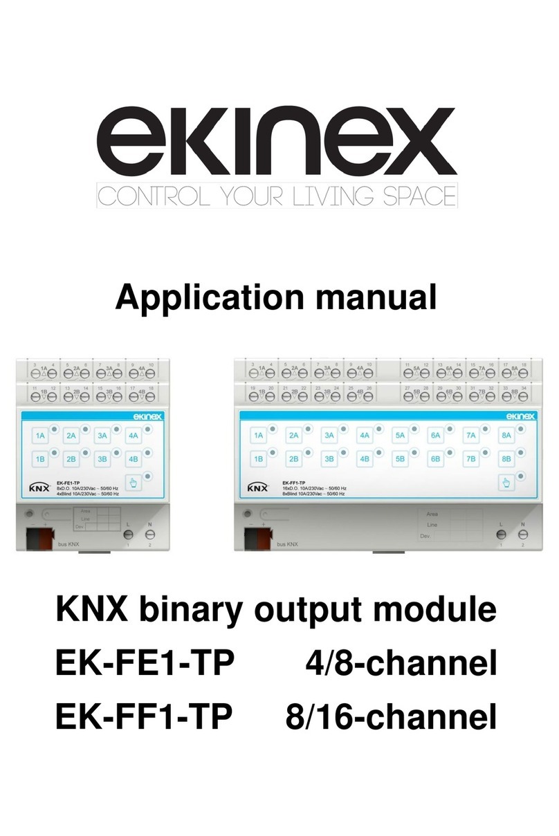
Ekinex EK-FE1-TP Instructions for use

Ekinex

Ekinex EK-FE1-TP Instructions for use

Ekinex EK-EA2-TP User manual

Ekinex

Ekinex EK-EA2-TP User manual

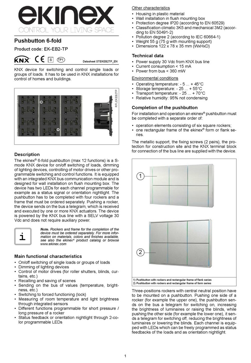
Ekinex EK-EB2-TP User manual

Ekinex

Ekinex EK-EB2-TP User manual

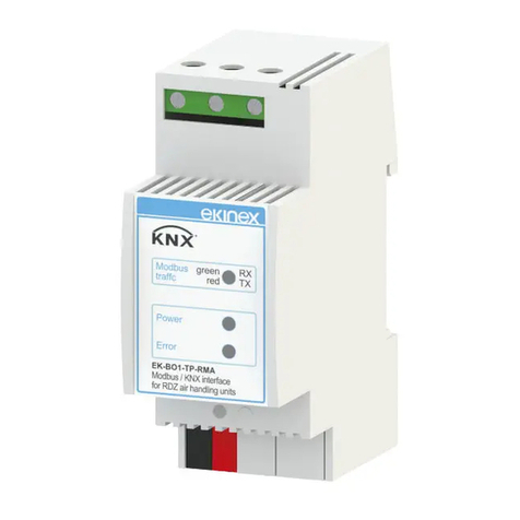
Ekinex EK-BO1-TP-RMA User manual

Ekinex

Ekinex EK-BO1-TP-RMA User manual

Popular Control Unit manuals by other brands

Jetter JX3-COM-PND installation manual

Jetter

Jetter JX3-COM-PND installation manual

Honeywell ADEMCO 4100SM Installation and setup guide

Honeywell

Honeywell ADEMCO 4100SM Installation and setup guide

Seraphim SRP-XXX-6PA-BB installation guide

Seraphim

Seraphim SRP-XXX-6PA-BB installation guide

Sanhua SBV Series instructions

Sanhua

Sanhua SBV Series instructions

REMS CamSys Instructions for installing

REMS

REMS CamSys Instructions for installing

Guangzhou Aosong Electronics DHT11 product manual

Guangzhou Aosong Electronics

Guangzhou Aosong Electronics DHT11 product manual

V2 CITY1-EVO manual

V2

V2 CITY1-EVO manual

Neptune NEITB58W Installation & operating manual

Neptune

Neptune NEITB58W Installation & operating manual

Emerson Numatics DeviceLogix G2-2 Series Quick start manual

Emerson

Emerson Numatics DeviceLogix G2-2 Series Quick start manual

Channel Vision Central C-0703 manual

Channel Vision

Channel Vision Central C-0703 manual

H3C MSR Router Comware 5 Series Guide

H3C

H3C MSR Router Comware 5 Series Guide

Yamaha disklavier DKC-850 quick start guide

Yamaha

Yamaha disklavier DKC-850 quick start guide

LIFE home integration ACER RG1R UNI DL Instructions and warnings for installation, use and maintenance

LIFE home integration

LIFE home integration ACER RG1R UNI DL Instructions and warnings for installation, use and maintenance

WDT GRANUDOS 10-S5 operating instructions

WDT

WDT GRANUDOS 10-S5 operating instructions

Glendinning EEC4 installation manual

Glendinning

Glendinning EEC4 installation manual

Aaeon PFM-540I user manual

Aaeon

Aaeon PFM-540I user manual

Eaton EOP5T07 installation instructions

Eaton

Eaton EOP5T07 installation instructions

Toshiba V Series Operation manual

Toshiba

Toshiba V Series Operation manual

manuals.online logo
manuals.online logoBrands
  • About & Mission
  • Contact us
  • Privacy Policy
  • Terms and Conditions

Copyright 2025 Manuals.Online. All Rights Reserved.