Ekinex EK-EQ2-TP- Series User manual

1
Room temperature controller
with LC-display
Codes: EK-EP2-TP-...
EK-EQ2-TP-... (with R.H. sensor)
Main functional characteristics
The characteristics common to all versions are:
• Temperature measuring through integrated sensor with
possibility of sending the value on the bus
• 2-point (on/off) or proportional (PWM or continuous)
room temperature regulation
• Ventilation control with continuous or 3-speed regula-
tion
• Seasonal modes: heating and cooling with possibility of
local or via bus seasonal changeover
• Operating modes: comfort, standby, economy and bu-
ilding protection with different setpoint for heating and
cooling
• Manual or automatic control of fan-coil units with 2 or
4-pipes hydraulic distribution
• Automatic switching of the operating modes depending
on presence or window opening
• Weighted average of two temperature values
• Temperature displaying (measured, setpoint and
outdoor values as °C or °F), alarms and errors (with
alphanumeric coding)
• Floor temperature limitation and antincondensation (for
radiant panels)
• Antistratication function
• Automatic switching between operating modes through
card holder contact
• Delayed start of a fan (“hot-start”) with time-scheduling
or depending on the water temperature measured at
the coil for thermal exchange
• Window opening reporting
The EK-EQ2-... versions offer additional functions for:
• Relative humidity measuring through the integrated
sensor with possibility of sending the value on the bus
• Humidication and dehumidication control
• Sending on the bus of the condition internal or external
with regard to a congurable comfort area
• Calculation of psychrometric values (dew-point tempe-
rature and perceived temperature)
• Displaying of perceived temperature, relative humidity
(measured and setpoint in %) and CO2concentration
(in ‰, received from the bus)
Other characteristics
• LC-display with adjustable backlight
• 2 rockers for device control
• 4 leds for each rocker freely programmable
• Case in plastic material
• Wall installation in round or square ush mounting box
with 60 mm distance between xing holes
• Protection degree IP20 (according to EN 60529)
KNX thermostat with LC-display for the independent ther-
mal regulation of a room or a zone. It has to be used in
KNX installations for control of homes and buildings.
Description
The ekinex®room temperature controller is a KNX S-mo-
de device for the independent temperature regulation of
a room or a zone in a building. In combination with one
or more KNX actuators, the room temperature controller
is able to control the heating and cooling emission of a
series of terminal units for the thermal exchange (such
as radiators, fan-coils, oor and ceiling radiant panels,
etc.). The device is provided with a LC-display with adju-
stable backlight, a sensor for temperature measuring and
two freely congurable inputs for the connection of e.g.
window contacts or temperature sensors. The device is
equipped with an integrated KNX bus communication
module and is designed for wall installation on a ush
mounting box. For controlling the room temperature con-
troller functions the integrated 2-fold pushbutton is used.
It is provided with four LED for each channel programma-
ble e.g. as status feedback or orientation nightlight. The
device is powered by the KNX bus line and does not re-
quire any auxiliary power supply.
EK-EQ2-... versions
The EK-EQ2-... versions are provided with a relative hu-
midity sensor and additional functions that use the physi-
cal value measured by the sensor.
Versions and accessories
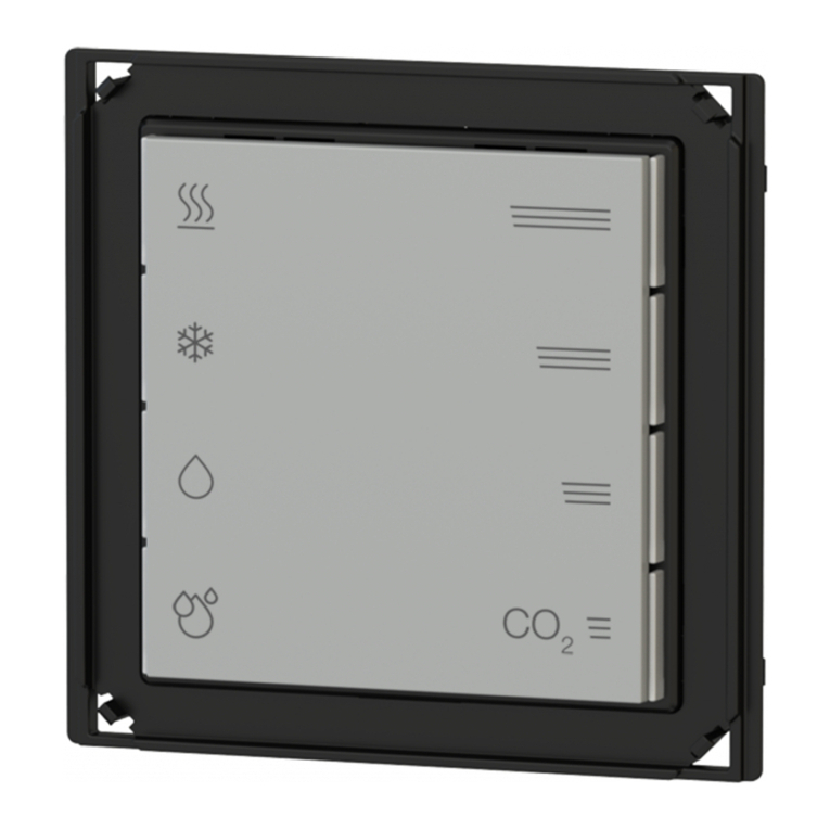
The device has to be completed with a set of 2 square ro-
ckers specic for the room temperature controller; depen-
ding on the version, a square frame of the form or ank
series may be necessary. A metallic support, the xing
screws and the terminal for connection of the KNX bus
line are delivered with the device.
Note. Rockers and frame (when necessary) for the
completion of the device must be ordered separa-
tely. For more information on materials, colors and
nishes available, see also the ekinex®product ca-
talog or browse www.ekinex.com
i
Datasheet STEKEQ2TP_IT
TP1
S
RFLEKEQ2TP
Code LED colors Accessories
EK-EP2-TP blue / green set of rockers
EK-TSQ-G...-EP2
and square frame
form (EK-FOQ-...) or
ank (EK-FLQ-...)
EK-EP2-TP-RW white / red
EK-EQ2-TP blue / green
EK-EQ2-TP-RW white / red
EK-EP2-TP-BG-NF blue / green set of rockers
EK-TSQ-G...-EP2
(on the ‘NF (No Frame)
version no frame has to be
mounted)
EK-EP2-TP-RW-NF white / red
EK-EQ2-TP-BG-NF blue / green
EK-EQ2-TP-RW-NF white / red

2
• Classication climatic 3K5 and mechanical 3M2 (accor-
ding to EN 50491-2)
• Pollution degree 2 (according to IEC 60664-1)
• Weight 70 g (85 g with mounting support)
• Dimensions 82 x 75 x 35 mm (WxHxD)
Technical data
• Power supply 30 Vdc from KNX bus line
• Current consumption < 13 mA
Environmental conditions
• Operating temperature: −5 ... +45°C
• Storage temperature: −25 ... +55°C
• Transport temperature: −25 ... +70°C
• Relative humidity: 95% not condensing
Device operation
The device can be congured to operate as a stand-alone
device (local control) or slave device (control via bus).
Using as a stand-alone device
The control is carried out locally with the two rockers on
the front side of the device. During the conguration it is
possible to enable selectively the available functions. De-
pending on the conguration done with ETS, it is possible
to:
• change temporarily the setpoint of the current operating
mode;
• display an information sequence;
• control a ventilation terminal device;
• change the setpoint values for the operating modes
comfort, standby and economy;
• adjust the intensity of the backlight;
• display the physical address and the rmware release
of the device;
• change the heating/cooling mode (seasonal changeo-
ver).
Using as a slave device
The control is carried out remotely by another KNX de-
vice acting as a supervisor that sends to the thermostat
via bus the operational parameters: e.g. setpoint values,
operating modes or seasonal modes. The possibility of
changing locally the operational conditions, received via
bus by the master device, are limited in comparison to
the use as a stand-alone device and are indicated on the
display by the symbol M (Manual). In this case, the ope-
rating parameters of the room temperature controller can
be changed centrally at the master device.
LC-display
1
4
2
3
1) + (plus) symbol: increase of value
2) symbol: display of information (short pressing), change of setpoint (long
pressing), conrm of a setting
3) symbol: ventilation control, change of operating mode, operation exit
4) - (minus) symbol: decrease of value
The thermostat has an LC-
display with adjustable bac-
klight that occupies vertical-
ly the left half of the front
side. Depending on the in-
formation to be displayed,
a combination of digits and
symbols can be switched
on. The light intensity emit-
ted from the display can be
set during the conguring
with ETS and later adjusted
manually to the light condi-
tions of the room.
Simb. Meaning
Temperature (in °C or °F), relative humidity (in %), CO2
concentration (in ‰)
Alarm, error Economy
Window opening Standby
CO2concentration Comfort
Internal temperature Heating
External temperature Manual
Relative humidity Slave
Setpoint Cooling
Building protection Fan control
Symbols
Seasonal operating modes
The device allows the control of the room temperature for
both modes of operation of the thermal system: heating
and cooling. If a 4-pipe hydraulic distribution is present,
the device can be congured so that the switching betwe-
en heating and cooling modes is done automatically for
the same room and in the same day, if the central system
provides simultaneously warm and cold conveying uids.
The active mode of the system is displayed by an appro-
priate symbol.
Operating modes
Symbol Seasonal operating mode / device status
Heating seasonal operating mode, request of the device satised or
achieved setpoint
Heating seasonal operating mode, device requesting heating or
setpoint not achieved
Cooling seasonal operating mode, request of the device satised or
achieved setpoint
Cooling seasonal operating mode, device requesting cooling or
setpoint not achieved
Rockers
The symbols on the rockers are predened and cannot be
modied. The areas marked by the symbols + (plus) and -
(minus) allow the change of the temperature setpoint, the
fan speed or to select a setting, while those marked by the
symbols allow e.g. the displaying of a sequence of
information, the change of the operating mode, the venti-
lation control, the seasonal changeover (heating/cooling)
or the access and conrmation a setting change.

3
The device has four operating modes with setpoint values
to be set independently for the operation in heating and
cooling. The setpoint values as well as the using during
the day of the various operating modes depend on a num-
ber of specic factors such as the building type, the use
of the room, the individual perception of heat and cold,
the ‘inertia characteristic of the room terminals, etc. and
should be carefully considered with the planner of the he-
ating system, the customer and the user.
Comfort
The comfort operating mode is generally set when people
occupy continuously a room.
Standby
The standby operating mode is set in case of absence
of short duration from the room. This mode provides a
small attenuation of the temperature compared to comfort
mode; the attenuation assumes a different direction de-
pending on the seasonal mode setting (lower temperature
for heating, higher temperature for cooling).
Economy
The economy operating mode is set for example in case
of prolonged absence from the room, during the night
hours, etc. and provides an bigger attenuation of tempe-
rature larger than the standby mode.
Building protection
The building protection operating mode is provided with
a temperature threshold; when exceeded, warm or cold
conveying uid is requested to the thermal generator to
avoid potential damages to the building (equipment, fur-
nishings, devices) caused by too low (frost protection) or
too high (overheating protection) internal temperatures.
The building protection function is effective only when the
thermal generator (boiler or chiller) is regularly operating.
If congured and connected to a window contact, the
device automatically switches to the building protection
mode at the window opening and switches back to the
previous mode at the window closing.
Mounting position
For the temperature control function the value of the room
temperature may be measured by the temperature sen-
sor integrated in the device, by another KNX temperature
sensor, by a temperature sensor connected to one input,
or be calculated as a weighted average value of two dif-
ferent sources.
Note. If the device is in the building protection
mode, when the temperature exceeds the threshold
setting, the valve of the hydraulic circuit is opened
even if the fan is switched off.
i
Symbol Fan operation
Switched off mode (OFF): the fan is switched off
and the regulation can not activate it, indipendently
from the the difference between the measured tem-
perature and the current temperature setpoint.
Automatic mode (A): the fan speed is automatically
regulated depending on the difference between the
measured temperature and the current temperature
setpoint.
Manual mode: the fan speed is manually forced
to the level corresponding to the number of bars
switched on (from 1 to 5).
1,50 m
min 0,3 m
Changing operating mode
If the device is congured to operate as a slave, the set-
ting of the operating mode is done via bus by another
KNX device with supervising function (such as a timer or
a centralised control and visualisation unit) of the building
automation system. The only change of operating mode
enabled manually is the recalling of the comfort mode
for a congurable time interval with ETS. If the device is
congured for stand-alone operation, the change of the
operating mode is done manually using the rockers for
the control of the room temperature controller functions.
Ventilation control
The device allow the control of the ventilation function.
The regulation may be continuous or stepwise (max 3
speed levels).
If the temperature value measured by the integrated sen-
sor is used, for an optimal temperature control the device
must be installed taking care of:
• installing the device on an inner wall of the room at a
height of about 1.5 m from the oor;
• not shielding the device with curtains, furniture or other;
• verifying that from the duct connected to the wall box
does not come airows that might affect the temperatu-
re measurement;
• avoiding the installation close to heat sources (such as
domestic appliances or lighting devices), pipes for the
distribution of hot or cold water and terminal devices for
heating and cooling;
• avoiding the installation where the device may be
subject to direct sunlight through glass surfaces.
If these conditions can not be satised, it is appropriate to
use a weighted average value between two temperature
values measured in the same room according to the dif-
ferent possibilities offered from the device (temperature
sensor connected to an input or a KNX temperature sen-
sor). If a second temperature value can not be measured,
it is also possible to correct the value measured by the
sensor integrated in the device using the appropriate of-
fset parameter in the ETS application program.
Mounting
The device has degree of protection IP20, and is therefo-
re suitable for use in dry interior rooms. The installation of
the device requires the following steps:
a) x the metallic support (f) with the screws supplied (e)
on the wall box (g);
b) if required, snap a square frame (d) of the form or ank
series, inserting it from the rear of the device (b) ;
c) connect the sensors or the contacts required to the
4-poles screw terminal block on the rear of the device;
d) insert the terminal for the bus (red/black), previously
connected to the bus cable, in its slot on the rear side

4
(see also: “Connection of the KNX bus line”. At this
point it is recommended to carry out the commissio-
ning of the device (see also “Conguration and com-
missioning”) or at least the download of the physical
address;
e) install the device (b) on the metallic support (f) throu-
gh the spring system, tightening then the two screws.
Mounting the device follow also the indication TOP (ar-
row tip pointing up) on the rear side of the device;
f) snap the two rockers (a) onto the device for the opera-
tion of the room temperature controller.
The device can only be mounted on a round or square
wall ush mounting box with 60 mm distance betwe-
en xing holes. If necessary, the metallic support for
mounting on the wall box can also be ordered separately
using the code EK-SMQ.
Switching and display elements
The device is equipped with a backlighted LC-display,
2 mechanisms for rockers mounting, 4 programmable
LEDs for each channel, a programming LED and a pro-
gramming pushbutton.
Switching elements
• Pushbutton (3) for switching between the normal and
programming operating modes
• Mechanisms (8) for room temperature control functions
to be completed with 2 square rockers
Display elements
• LC-display (1) with digits and symbols for displaying the
operating conditions of the device
• Red LED (4) for indication of the active operating mode
(on = programming, off = normal operation)
• Eight freely programmable LEDs with lightguide (5);
e.g. as status feedback or as orientation nightlight
Measuring elements
The devices is provided with two sensors:
• temperature sensor (not visible, positioned behind the
passage 7);
• relative humidity sensor (6).
Temperature sensor
The integrated temperature sensor measures the tempe-
rature value in a range from 0 °C to +40 °C with a re-
solution of 0.1 K. The measured value can be corrected
by the environmental inuences by means of an offset
parameter. In order to avoid that too rapid temperature
uctuations negatively affect the regulation process, an
acquisition lter can be set. If necessary, for the regula-
tion can be used a weighted average between the value
measured by the integrated sensor and another tempera-
ture value measured in the room by a temperature sensor
connected to one of the inputs of the device or received
via bus by another KNX device. The value measured by
the sensor can be sent on the bus.
Relative humidity sensor (only for EK-EQ2-TP-...)
The measurement of the relative humidity of the room air
mass signicantly extends the functions of thermal regu-
lation and allows to increase comfort and safety of ope-
ration. In combination with the HVAC system, the device
allows to perform a real building climatic control indepen-
dently for each room or zone, adding to heating and co-
oling of the possibility of controlling the dehumidication
and humidication of the rooms. The value measured by
the sensor can be sent on the bus..
Note. Programming pushbutton and LED are ac-
cessible from the front side of the device. The de-
vice addressing may be easily carried out after the
assembly of the frame, removing the rockers. Once
the addressing has been carried out, the device
conguration can be later downloaded without pres-
sing the programming pushbutton.
i
abd f g
e
a) Square rockers 40x40 mm (to be ordered separately)
b) Device
c) Screws for xing the device on the support
d) Frame of form or ank series (to be ordered separately)
e) Screws for xing the support on the wall box
f) Mounting support for wall box
g) Wall box (not delivered by SBS)
c
ESEKEQ2TP
1) LC-display
2) Fixing screws for support
3) Programming pushbutton
4) Programming LED
5) Lightguide for rockers LED
1
2
4
36
7
5
6) Relative humidity sensor
7) Temperature sensor
8) Mechanisms for rockers’ mounting
9) Terminal for bus line connection
10) Terminals for input connection
9
8
10
DCEKEQ2TP

5
Connection of the KNX bus line
The connection of the KNX bus line is made with the ter-
minal block (black/red) included in delivery and inserted
into the slot of the housing.
Characteristics of the KNX terminal block
• spring clamping of conductors
• 4 seats for conductors for each polarity
• terminal suitable for KNX bus cable with single-wire
conductors and diameter between 0.6 and 0.8 mm
• recommended wire stripping approx. 5 mm
• color codication: red = + (positive) bus conductor,
black = − (negative) bus conductor
Connection of the inputs
The connection of the inputs is made with the screw ter-
minals (10) located at the rear side of the device. The
maximum cable length is 10 m.
Characteristics of the terminals
• screw clamping of conductors
• maximum cross section of conductor 1 mm² (multi-wire)
• recommended wire stripping approx. 5 mm
• torque max 0.2 Nm
Available applications
If congured as analogic, to an input it is allowed exclu-
Warning! In order to supply the KNX bus lines use
only KNX bus power supplies (e.g. ekinex EK-AB1-
TP or EK-AG1-TP). The use of other power supplies
can compromise the communication and damage
the devices connected to the bus.
!
Warning! The electrical connection of the device
can be carried out only by qualied personnel. The
incorrect installation may result in electric shock or
re. Before making the electrical connections, make
sure the power supply has been turned off.
!
ELEKEQ2TP
+
-
KNX
bus
NTC sensor
Contact
sively the connection of NTC temperature sensors with
characteristic resistance value of 10 kΩ at 25°C, β = 3435.
Conguration and commissioning
Conguration and commissioning of the device require
the use of the ETS®(Engineering Tool Software) program
V4 or later releases. These activities must be carried out
according to the design of the building automation system
done by a qualied planner.
Code Application program
(## = release)
Comm.
objects
(max nr.)
Group
addr.
(max nr.)
EK-EP2-TP-...
APEKEP2TP##.knxprod
144 144
EK-EQ2-TP-...
APEKEQ2TP##.knxprod
144 144
Note. The conguration and commissioning of KNX
devices require specialized skills. To acquire these
skills, you should attend the workshops at KNX cer-
tied training centers.
i
Commissioning
For commissioning the device the following activities are
required:
• make the electrical connections as described above;
• turn on the bus power supply;
• switch the device operation to the programming mode
by pressing the programming pushbutton located on
the front side in the area for the mounting of the ro-
ckers. In this mode of operation, the programming LED
is turned on;
• download into the device the physical address and the
conguration with the ETS®program.
Warning! Each input of the device is independently
congurable as digital or analogic. The connection
to an input of a device which does not match the
parameter conguration carried out with ETS cau-
ses the impossibility to perform the desired function.
!
Conguration Application
Digital
[DI] window sensor
[DI] card holder sensor
[DI] anticondensation sensor
Analogic
[AI] coil battery temperature sensor
[AI] room temperature sensor
[AI] antistratication temperature sensor
[AI] oor surface temperature sensor
[AI] outdoor temperature sensor
[AI] generic temperature sensor (NTC type)
Conguration
For the conguration of the device parameters the corre-
sponding application program or the whole ekinex®pro-
duct database must be loaded in the ETS program. For
detailed information on conguration options, refer to the
application manual of the device available on the website
www.ekinex.com.
At the end of the download the operation of the device
automatically returns to normal mode; in this mode the
programming LED is turned off. Now the bus device is
programmed and ready for use.
Displaying physical address and rmware release
If enabled for this purpose with ETS, the device can di-
splay anytime its physical address and rmware release
by the combined pressing of rockers. To display the in-
formation, simultaneously press – (minus) and on
the upper rocker for more than 3 s. The display shows in
sequence the number of area (A), line (L), device (d) and
the rmware release (F). To scroll through the information
press on the upper rocker. The display returns to the
default information at the end of the time interval set with
ETS or pressing on the lower rocker.

6
Warnings
• Installation, electrical connection, conguration and
commissioning of the device can only be carried out by
qualied personnel in compliance with the applicable
technical standards and laws of the respective countri-
es
• Opening the housing of the device causes the imme-
diate end of the warranty period
• In case of tampering, the compliance with the essential
requirements of the applicable directives, for which the
device has been certied, is no longer guaranteed
• ekinex®KNX defective devices must be returned to the
manufacturer at the following address: SBS S.p.A. Via
Novara 35, I-28010 Vaprio d’Agogna (NO) Italy
Other information
• This datasheet is aimed at installers, system integra-
tors and planners
• For further information on the product, please contact
the ekinex®technical support at the e-mail address:
com
• Each ekinex®device has a unique serial number on
the label. The serial number can be used by installers
or system integrators for documentation purposes and
has to be added in each communication addressed to
the SBS technical support in case of malfunctioning of
the device
• ekinex®is a registered trademark of SBS S.p.A.
• KNX®and ETS®are registered trademarks of KNX As-
sociation cvba, Brussels
© SBS S.p.A. 2017. The company reserves the right to make changes to
this documentation without notice.
Marks
• KNX
• CE: the device complies with the Low Voltage Directi-
ve (2014/35/EU) and the Electromagnetic Compatibility
Directive (2014/30/EU). Tests carried out according to
EN 50491-5-1:2010, EN 50491-5-2:2010
Maintenance
The device is maintenance-free. To clean use a dry cloth.
It must be avoided the use of solvents or other aggressive
substances.
Disposal
At the end of its useful life the product descri-
bed in this datasheet is classied as waste
from electronic equipment in accordance with
the European Directive 2012/19/EU (WEEE
recast), and cannot be disposed together
with the municipal undifferentiated solid wa-
ste.
Documentation
This datasheet refers to the release A1.0 of the ekinex®
devices EK-EP2-TP and EK-EQ2-TP, and is available for
download at www.ekinex.com as a PDF (Portable Data
Format) le.
File name Device release Updating
STEKEPQ2TP_EN.pdf A1.0 04 / 2017
Warning! Incorrect disposal of this product may
cause serious damage to the environment and hu-
man health. Please be informed about the correct
disposal procedures for waste collecting and pro-
cessing provided by local authorities.
!
Dimensions [mm]
82
80
53
29 8
37
DCEKEQ2TP
Other manuals for EK-EQ2-TP- Series
1
This manual suits for next models
9
Table of contents
Other Ekinex Temperature Controllers manuals
Popular Temperature Controllers manuals by other brands

LEGRAND
LEGRAND 5739 18/19 user manual

Flex-a-Lite
Flex-a-Lite 31149 Wiring diagram

EnOcean
EnOcean Trio2Sys O2LINE 10020057 Series Installation and operating manual

Secure
Secure SES 302 User and installation instructions

AKO
AKO AKO-D16323 installation instructions

Omron
Omron EJ1 EtherCAT instruction manual