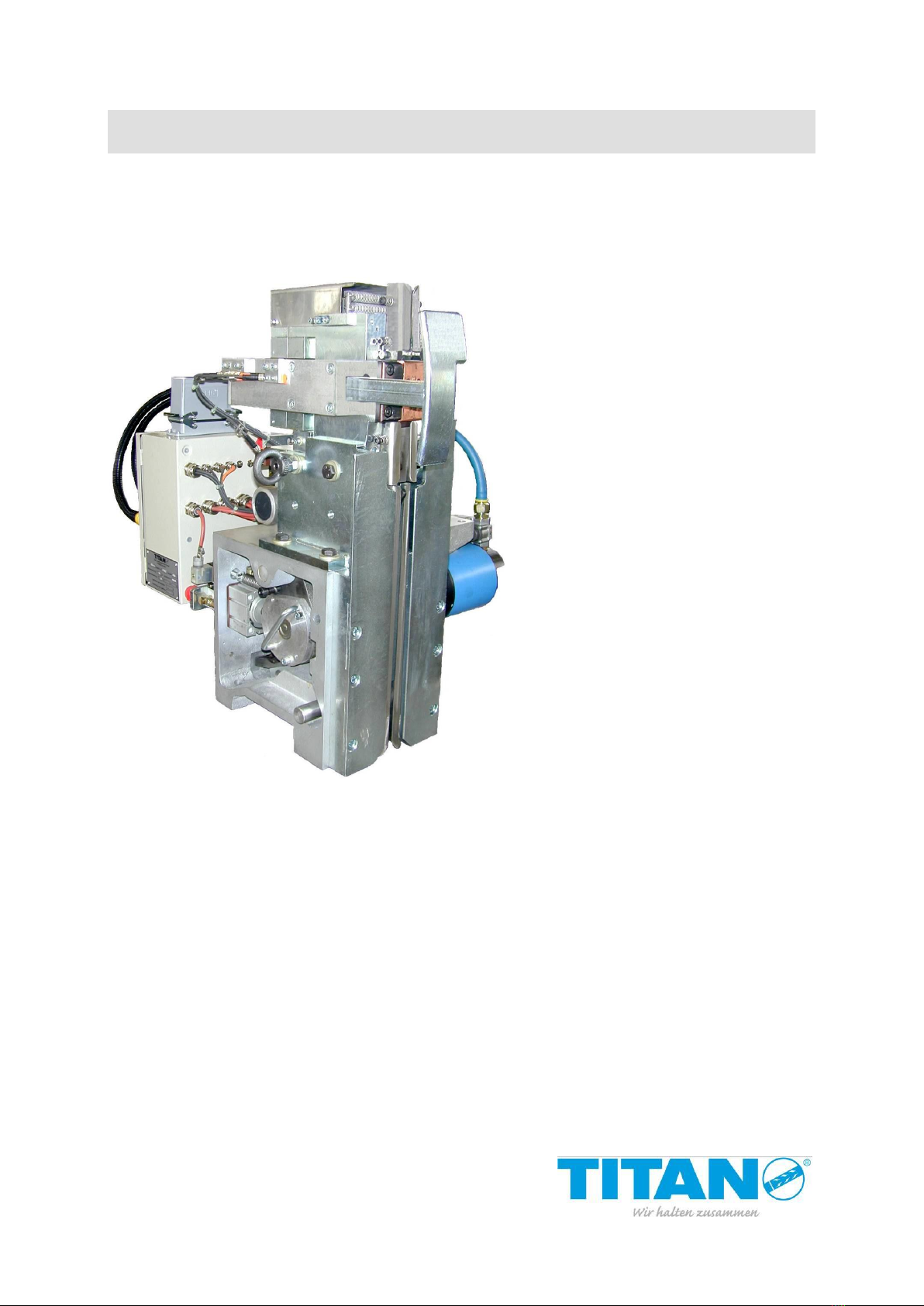
Titan VS-32-L Manual

Operating and Maintenance Instructions
VS-32-L
130003
Pneumatic
Strapping head
for steel strap
Seal
Important!
Do not throw these instructions away.
The customer agrees to make these
operating instructions understandable
to all operating and service personnel.
B 13 GB 11/13

VS-32-L 2
Table of contents
Page
1. Manufacturer details....................................................................................................................3
2. General..........................................................................................................................................4
3. Safety regulation ..........................................................................................................................7
4. Life phases of the unit .................................................................................................................9
5. Technical data ........................................................................................................................... 11
5.1. Technical data of the welding unit..................................................................................... 12
5.2. Finding the time required for a strapping operation.......................................................... 13
5.3. Smallest support with different packing items................................................................... 14
5.4. Measurements and assembly dimensions VS-32-L ......................................................... 15
5.5. Pneumatic plan equipment (head control system)............................................................ 16
5.6. Functional time diagram.................................................................................................... 17
5.7. Arrangement and designations......................................................................................... 18
6. Designations.............................................................................................................................. 19
6.1. Switches and motors......................................................................................................... 19
6.2. Switches............................................................................................................................ 21
6.3. Positions of the switches, valves, pressure controllers and motors ................................. 22
7. Functional description.............................................................................................................. 23
7.1. Process description........................................................................................................... 23
7.1.1. Insertion of strap..................................................................................................... 23
7.1.2. Feed of strap, medium speed................................................................................. 23
7.1.3. Strap feed, precise movement................................................................................ 24
7.1.4. Closing strap gripper 1............................................................................................ 24
7.1.5. Transport back of strap........................................................................................... 24
7.1.6. Tensioning the strap ............................................................................................... 24
7.1.7. Closing strap gripper 2............................................................................................ 25
7.1.8. Welding................................................................................................................... 25
7.1.9. Swivelling the welding station open........................................................................ 25
7.1.10.Swivelling the welding station back ........................................................................ 25
7.2. Positions on the cam gear ................................................................................................ 26
7.3. Description of the welding operation................................................................................. 27
8. Adjustments............................................................................................................................... 28
8.1. Setting switches B1 to B8 ................................................................................................. 28
8.2. Setting the zero position ................................................................................................... 30
8.3. Setting the clamping and opening positions ..................................................................... 30
8.4. Setting the air pressure..................................................................................................... 31
8.5. Setting the quantity of gas ................................................................................................ 33
8.6. Setting the distance between electrodes.......................................................................... 34
8.7. Setting the torch................................................................................................................ 35
8.8. Setting the welding parameters ........................................................................................ 36
9. Maintenance............................................................................................................................... 37
9.1. General ............................................................................................................................. 37
9.2. Maintenance intervals....................................................................................................... 38
9.3. Check seal ........................................................................................................................ 38
9.4. Lubricating points.............................................................................................................. 39
9.5. Maintenance of the transport unit ..................................................................................... 40
9.6. Maintenance of the clamp guide....................................................................................... 42
9.7. Maintenance of the cutter ................................................................................................. 44
9.8. Dismounting the torch, replacement of electrode ............................................................. 45
9.9. Dismounting and mounting the clamp............................................................................... 46
9.10. Dismounting and mounting the torch holder..................................................................... 47
10. Fault detection - remedy........................................................................................................... 48
11. Declaration of incorporation.................................................................................................... 50
B 13 GB 07/10

VS-32-L 4
2. General
Thank you very much for your confidence in the technology of TITAN
Umreifungstechnik GmbH & Co. KG!
These operating and maintenance instructions are meant to facilitate how to become
acquainted with the strapping machine and apply it as intended. The operating instructions
comprise important information on how the strapping machine can be used safely, as
intended und economically.
The operating instructions must permanently be available at the place the strapping head is
used. They must be read and applied by all staff members working with the strapping head.
Such works especially include operation, troubleshooting and maintenance.
Adjustment and maintenance works may only be performed
by trained technical staff.
Notes on the warning and information symbols:
Caution!
Is used in case of risks threatening life and health.
Attention!
Is used in case of risks which may cause damage to objects.
Note!
Is used for general notes and such notes whose disregard may result
in faults in the course of operations.
The item numbers (…) and designations used in these operating instructions refer to the
spare parts list or documentation on the electrical system.
Copyright © TITAN Umreifungstechnik GmbH & Co.KG 2011 All rights reserved.
The contents of this document must not be duplicated, handed to third parties, published or saved in any form,
neither fully nor partly, without prior written permission by TITAN Umreifungstechnik GmbH & Co.KG.
is a registered trademark of TITAN Umreifungstechnik GmbH & Co.KG.
B 13 GB 33/06

VS-32-L 5
The intended use of this strapping head is the bundling, combining and securing of
packing items in strapping machines.
Unintended use!
Strapping material must not be used for the hoisting of loads, this strapping head
may only be used as intended and specified above.
The strapping head VS-32-L meets German and European safety requirements and
complies with the provisions in the following EU directives:
See Declaration of incorporation!
The VS-32-L is the suitable strapping head for medium and heavy packing items;
it does not matter whether those items are steel or stone, wood or glass.
The VS-32-L combines most modern driving and control technology with the state of
the art of patented TIG shield gas welding technology.
All functions are released by solenoid valves. Valves are equipped with actuating
magnets 24 V DC (direct current voltage).
The mains voltage of the VS-32-L head is 400 V 50/60 Hz. The connected load of the
welding unit is 6,6 kVA. Protect by fuse 16 A (slow-blow).
The welding seal can only be opened by means of an appropriate tool (strap scissors or
the like). Sealing strength is at approx. 90 % of the load at rupture of the strap
(depending on strap quality and dimension).
Adjustable strap tension of 4000-20000 N permits a good adaptation of the strapping to
the packing item.
The strapping head can be supplied in the following designs: for strap widths of 19, 25
and 32 mm.
Power and compressed air feed lines have one detachable quick-acting coupling each.
The mechanical joint of the strapping head and the machine is possible at various fitting
surfaces by means of four M16 bolts at the bottom of the drive housing and two of them
at the top. If required, two further M12 bolts on the fitting surface of the holding device
on the right. After the loosening of the four screws and the disconnection of the electric
power and compressed air ports the head can be replaced quickly and without
problems.
B 13 GB 33/06

VS-32-L 6
Three compressed air motors and two compressed air cylinder perform all functions of
the strapping head.
Just compressed air being dewatered, filtered and oiled is used. Air pressure
(flow pressure with transport motor being switched on) should be 6 bar. The port cross
section of the feed line must be G 3/4“ or greater.
Air consumption per strapping operation with conduit dimensions amounting to 2000 x
1000 mm is 0,2 to 0,3 m³. Consumption during the transport of strap is
1,25 m³/min. The short-time peak consumption is at 2,5 m³/min.
The argon/welding gas consumption amounts to 2 l per seal. When a 50 l gas bottle
with a filling pressure of 200 bar is used, approx. 5000 seals are possible, in case of
300 bar approx. 7500 seals. The welding electrode can be ground approx. 100 times.
B 13 GB 07/10

VS-32-L 7
3. Safety regulation
Read the operating and maintenance instructions before the use of
the strapping machine.
Read instructions carefully.
Unauthorized individuals are not allowed to use the strapping unit
(machine)
It is urgently required that all safety and warning notes are
followed; we especially refer to the EU Machine Directive.
Before the strapping tool is put in operation, the machine area
must be locked such (protective fences / safety sensors) that
unauthorised individuals cannot get into the danger zone of the
machine.
The operating staff must be instructed precisely and made familiar
with the handling of the unit before operating the unit for the first
time.
The strapping machine may only be positioned and put in
operation in closed and dry rooms.
Operating the machine is appropriate in the temperature range +0
°C to +40 °C.
Do not deposit containers with liquids on the strapping tool or
strapping unit. No liquid must be allowed to penetrate the strapping
tool / strapping unit.
No persons or objects must stay in the area of operation of the unit
(machine) before the latter is put in operation.
Protective installations, covers and linings of the unit (machine)
must be checked before activation. They must neither be loose nor
have been removed.
Do not let your hands get into the channel area and below the
packing items during the strapping operation. Attention! Risk of
squeezing!
B 13 GB 07/10

VS-32-L 8
Before the beginning of cleaning works and / or troubleshooting the
strapping head must be put out of operation. Main switch at
position OFF.
Attention! Strap may tear! Do not stand in the alignment of the
strap.
Wear eye and face and hand protection when eliminating fault
strappings
When cutting the strap hold the upper parts firmly
(see figure).
Attention! The lower part of the strap jumps upward.
Consider the strong development of noise during longer
operations. Therefore, protect your health.
Exclusively use original TITAN spare parts! The use of spare
parts not made by TITAN excludes guarantee adjustments and
liability.
In automatic mode attention has to be paid that no squeezing
points may occur between the feeding installations (e.g. roller
conveyors) and the movable strapping unit.
We do not accept liability for alterations to the strapping
machine! Further, warranty/guarantee and these operating
instructions become inapplicable.
For safety regulations applying to
the TIG Inverter shield gas
welding unit see operating
instructions attached. TITANARG
L 250 TI
B 13 GB 07/10

VS-32-L 9
4. Life phases of the unit
Transport:
Attention! Do not stay beneath the load during lifting and
depositing. Order individuals standing in the hazardous area to
leave it. Minimum carrying capacity see technical data on page 11.
Putting the unit in operation:
The strapping machine may be put in operation by trained
technical staff only.
Setting, programming:
Setting and programming works related to the strapping unit may
only be performed by trained technical staff.
Operation, modes:
Manual mode:
Manual mode permits the implementation of individual works performed for testing and
troubleshooting. Further, manual mode is applied to take the strapping unit to home position.
Attention! During the touch control of the cam gear there is a risk
of squeezing at the strap guides and the counter plate.
Automatic mode:
Automatic processing of all movements.
In automatic mode attention must be paid that no points with the
risk of squeezing may occur between the feed installations (e.g.
roller conveyors) and the movable strapping unit.
B 13 GB 07/10

VS-32-L 10
Cleaning, maintenance, repairs:
Just trained technical staff is allowed to perform maintenance and
repair works on the strapping unit.
Attention! Before beginning with any maintenance work the
relevant staff must disconnect the strapping unit from the power
mains.
Attention! Wear protective glasses when cleaning the unit /
machine with compressed air.
Putting the unit out of operation, disassembly
Attention! When dismounting the strapping machine there is the
risk of squeezing.
Attention! Do not stay beneath the load during lifting and
depositing. Order individuals standing in the hazardous area to
leave it. Minimum carrying capacity see technical data on page 11.
Waste disposal
If packing material is to be disposed of, take it to the relevant
recycling container or admit it to the Dual System.
Should the strapping machine have to be disposed of at the end of its service life, separate
plastic material, steel and aluminium and dispose of such materials separately. In the same
way, motors and electric modules like control system, switches and cables must be admitted
to separate waste disposal. Take such elements to the appropriate waste management.
B 13 GB 07/10

VS-32-L 11
5. Technical data
Kind of drive: electro pneumatic, 3 motors and 2 cylinder
Strap conveying speed: 1,7 m/s
Connected load of the
welding unit: 6,6 kVA
Packing steel strap:
- widths: 19, 25, 32 mm
- thicknesses: 0,8-1,0 mm, Megaband to 0,8 mm
Kind of seal: TIG welding seal
Load at rupture of seal: approx. 80-90 % of the load at rupture of
seal (depends of quality, thickness and
surface of strap)
Electrode Ø: d = 2,4 mm ; l = 175 mm ; WS 2 turquoise
Welding gas: welding argon gas 4.6 (Ar. 99,996)
Gas consumption: 2 litre per seal
Gas nozzle: size 6
Sound emission: the sound pressure level acc. to DIN 45635
part 27 is 85 dB (AS)
Min. packing item dimensions:
straight packing item length: min. 150 mm
round packing item Ø: min. 700 mm
Strap tensions: 4000-20000 N adjustable
Air pressure: 5-6 bar flow pressure
Air consumption: approx. 0,2-0,3 m³ per strapping operation
Weight: 200 kg
Dimensions: l 680 x w 580 x h 750 mm
B 13 GB 33/06

VS-32-L 12
5.1. Technical data of the welding unit
Welding performance:
Adjusting range, continuous: 80 A / 13,2 V ... 200 A / 18 V
DB 100 % operation-on period: 80 A / 13,2 V
DB 60 % operation-on period: 155 A / 16,2 V
DB 50 % operation-on period: 200 A / 18,0 V
No-op voltage: approx. 15 –90 V
Mains connection:
Mains voltage: 3 x 400 V 50 / 60 Hz
Continuous / maximum rating: 1,5 / 5,0 kVA
Continuous / maximum current: 2,2 / 7,2 A
Fuse (slow-blow): 16 A
Connecting line: 4 x 1,5 mm² Cu
Power factor cos. phi: 0,9
Dimensions:
Height
(without carrying handles): 333 mm
Width: 287 mm
Depth: 448 mm
Weight: 20,25 kg
Protection: IP 23 Cooling: AF Insulating material class: H
Details of sound emission values:
The welding current source generates a sound level of < 68 dB (A) during no-load
operations and < 68 dB (A) in case of maximum admissible working point at standard
load according to VDE 0544-1 or EN 60974-1. Sound data are measured according to
DIN 45635. Measurements are performed at a distance of 1 m away from the welding
current source.
B 13 GB 33/06

VS-32-L 13
5.2. Finding the time required for a strapping operation
Example: Strap cross section 32 x 0,8 mm
Conduit size 1,5 x 1,5 m
Size of packing item 1,0 x 1,0 m
F1 Strap feed =
[s]movementpreciseadditionTime+
[m/s]speedtransportmax. [m]lengthonduitC
=
s8,0+
m/s1,7m6
= 4,3 s
F2 Clamping strap = fixed time = 0,3 s
F3 Strap return =
( )
]s/m[speedtransport.max [m]itempackingncecircumfere-[m]lengthconduit
=
( )
m/s1,7 m4-m6
= 1,2 s
Head forward = e.g. = 2,0 s
F4 Tensioning strap =
]s[momentdownlugtouedadditiontime+
[mm/s]speedensioningtmax. [mm]engthlTensioning
=
s5,0+
mm/s350mm80
= 0,7 s
F5 Clamping, cutting = fixed time = 0,6 s
F6 Sealing = selected = 1,5 s
Switching = = 0,5 s
Ignition = = 0,2 s
Sealing = selected = 1,5 s
Cooling = selected = 1,7 s
F7 Seal, released = fixed time = 1,3 s
F8 Head backward,
retraction = selected = 1,0 s
Total time Σ16,8 s
B 13 GB 04/13

VS-32-L 14
5.3. Smallest support with different packing items
VS 32-L | VS 32-R
Expansive packing item:
180 mm | 150 mm
Slit coil:
180 mm | 150 mm
Hexagon pipe bundle:
-- | 160 mm
Round packing item:
Ø 800 mm | Ø 700 mm
150
150
>15
160
For small packing units,
design R
B 13 GB 26/06

VS-32-L 15
XX XXX
Free space to
swivel the welding
station open
425
310
245
80 140
55
Channel
outlet
35
Free space
for SEK 01
25
325
4
40
30
22
50
65
77
300 68
750 600
Modular dimension 680mm
160 30
Middle strap
575 38
50
110 110
5
115
140
Multi-functional
block
41
Head deactivation
Channel
intake
Multi-functional
block
405
Intake of strap
140
Free space
for assembly
counterroller
130 15
M16
20
100
80
75
51
50
Welding
torch
M12
80
Middle seal
Gas port
Control cable
Welding current
235
M16
Welding and
electric console
SEK 01
5.4. Measurements and assembly dimensions VS-32-L
B 13 GB 33/06

VS-32-L 16
B 13 GB 11/13
5.5. Pneumatic plan equipment (head control system)
Blowing device
Welding station
throttled
A
B
Quick-acting
coupling
Microspray oiler
Pos. 635
(Pos. 636)
Pos. 690
Pos. 700
2/2 distribution control valve
5/3 distribution control valve
5/2 distribution control valve
3/2 distribution control valve
Machine maintanence unit
Multi-functional block
Pressurre control valve
Pos. 620,
632, 653,
680
Pos. 600
Pos. 845
Pos. 710
DR1
Pos. 569
DR2
DR3
Lift cylinder
transport slide
Pressing cylinder
tensioning rocker
Transport motor
tensioning motor
Sealing motor
Z 1
Z2
M1
M2
M3

VS-32-L 17
t8
Y15
B15
Y1 Y2 prec.
t5
0,5 s
Commutation
rapid
B7
Y5
Y16
t3
F8
0
K
B3
0
W
B4
F
0
K
Pos.
F
Y6
precise
B1-B2
B1 - Strap stopping switch
B2 - Counter switch
B3 - Zero position
B4 - Position switch K-W-F
B7 - Head before packing item
B8 - Head on packing item
B14 - Start precise movement
B15 - Head at the rear
B16 - Head at the front
Y1 - Air valve, medium speed (adjustable)
Y2 - Air valve, fast speed
Y3 - Transport motor forward
Y4 - Transport motor backward
Y5 - Sealing motor
Y6 - Tensioning motor
Y10 - Gas valve
Y15 - Blowing device
Y16 - Tensioning rocker pressed
rapid v = 1,7 m/s
Y2, Y3 B14
Y1
mean
B3
B4
t4 min. 8 s after-flow
Y5
Pos.
F
F7
Pos.
W
W
K
F
0
B3
Pos.
0
F1
Strap feed
t5
Welding
Clamping
cutting
Tensioning
strap
Strap return
head forward
Clamping
strap
t1 - Tensioning strap OFF
t3 - Cooling time sealing
t4 - Gas after-flow
t5 - Sealing time
t6 - Welding flow
t7 - if B14 does not exist
t8 - Air-cleaning device
t9 - Overlapping of strap
t10 - Strap circulation check
prec.
precise
Y5
B4
Y4
B8
B16 Y6
Y2 B2
Gas pre-flow
Y10
rapid mean precise
Y5
B2
B4
Pos.
W
F2
Pos.
0
0
F
B4
K
K
F3
Pos.
K
F4 F5
K
Pos.
K
F
0
F6
B4
W
Pos.
W
Head
backward
swivelling in
Releasing
seal
W
5.6. Functional time diagram
B 13 GB 36/09

VS-32-L 18
Fig. 1: Main assembly units
D
C
B
A
5.7. Arrangement and designations
The strapping head comprises the following main assembly units (see fig. 1).
A: Transport and tensioning unit:
The transport and tensioning unit transports the strap.
When being returned the strap is drawn narrowly around the packing item and
tensioned according to the tensioning force preset.
B: Welding station:
The welding station (sealing unit) is a cam controlled unit. It clamps the ends of
the strap, cuts the strap and forms the seal by means of the welding torch.
C: Multi-functional block:
The multi-functional block is equipped with pneumatic control elements being
required to adjust all speeds and strap tensions on the strapping head.
D: Welding and electric console:
Device to feed the torches with welding gas and welding current; it also comprises
the electrical units for the direct gas flow and current flow control (e.g. solenoid
valve etc.), further the electrical link between the strapping head and the machine
control system.
B 13 GB 36/09

VS-32-L 19
6. Designations
6.1. Switches and motors
Actuating magnets:
(The designations of the magnets on the valves have been taken from the pneumatic
diagram in section 5.6 and the functional time diagram in section 5.5)
Air valve, medium speed (adjustable) Y1
Air valve, fast speed Y2
Transport motor forward Y3
Transport motor backward Y4
Sealing motor Y5
Tensioning motor Y6
Transport slide Y7
Gas valve Y10
Head forward Y13 on the machine
Head backward Y14 on the machine
Blowing device Y15
Tensioning rocker pressed Y16
Control elements:
Strap stop switch B1
Counter switch B2
Zero position B3
Stop position K-W-F B4
Head before packing item B7
Head on packing item B8
Service switch strap insertion B9
Service switch seal B10
Start precise movement B14 in the conduit
Head at the rear B15 on the machine
Head at the front B16 on the machine
Accumulator full B17 on the machine
Accumulator empty B18 on the machine
End of strap B19 on the machine
Motors:
Transport motor M1
Tensioning motor M2
Sealing motor M3
Cylinder:
Lift cylinder transport slide Z1
Pressing cylinder tensioning rocker Z2
B 13 GB 33/06

VS-32-L 20
Pressure control valves:
Main maintenance unit (fast speed) DR1
On the multi-functional block:
Pressure controller (precise motion) DR2
Pressure controller (medium speed) DR3
Time elements:
Tensioning strap OFF t1
Ignition ON t2
Cooling time t3
Further flow of gas t4
Sealing time t5
Welding flow t6
Start precise movement t7 if B14 not available
Cleaning burner cell t8
Monitoring time strap overlapping t9
Monitoring operating time:
Feed / Return / Tensioning / Welding / Seal
B 13 GB 11/13
Table of contents
Other Titan Industrial Equipment manuals
Popular Industrial Equipment manuals by other brands

Pfannenberg
Pfannenberg PWS 7032-24V Series operating manual

CommScope
CommScope EPX G2 user manual

Bosch
Bosch Rexroth TS 2plus Assembly instructions

ABB
ABB HT577436 Operation manual

SCHUNK
SCHUNK GWK Series Assembly and operating manual

Sumitomo Drive Technologies
Sumitomo Drive Technologies PARAMAX SFC operating manual