01900338-M 2/20/2014
INSTALLATION
WARNING:
SAFETY FIRST!! READ AND UNDERSTAND THE SAFETY INSTRUCTIONS BEFORE PROCEEDING WITH ANY
INSTALLATION.
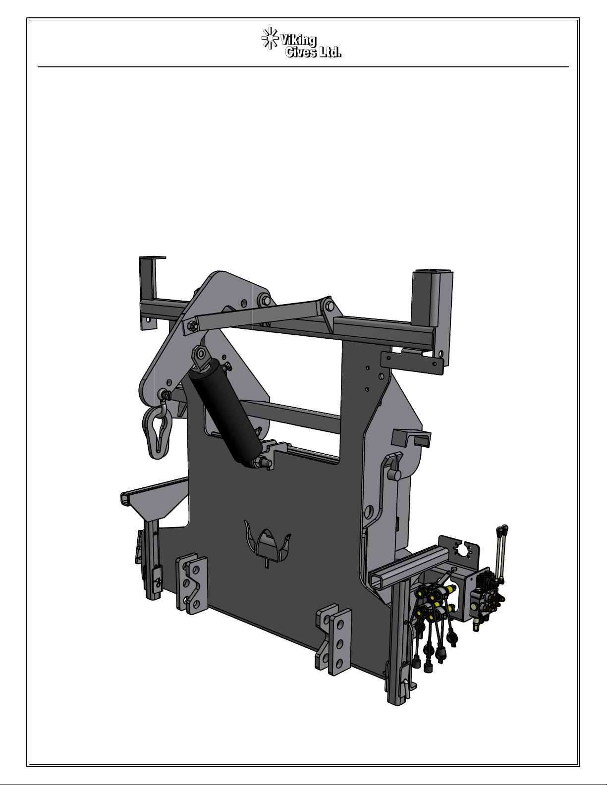
Viking-Cives LTD manufactures various models of front plow hitches such as the “Low Mount”, “Standard/Fixed”, “Power-
tilt” and “Tilt Detach”. While each of these hitches vary in style from one model to the next, the basic installation process remains the
same for all models.
NOTE: These installation instructions are intended as a guide to aid in the mounting of your Viking-Cives Plow
Harness/Hitch. All dimensions provided in these instructions are approximate and could vary due to variables such as: chassis make
and model, tire size, type of suspension, customer preference, and/or unknown interference caused by immovable attachments.
Viking-Cives LTD assumes no responsibility/liability for improper plow harness installation, unless installed by Viking-Cives LTD.
Plow harness mounting location should be discussed with the end-user, chassis dealer and the installer prior to beginning installation
in order to achieve the best possible installation.
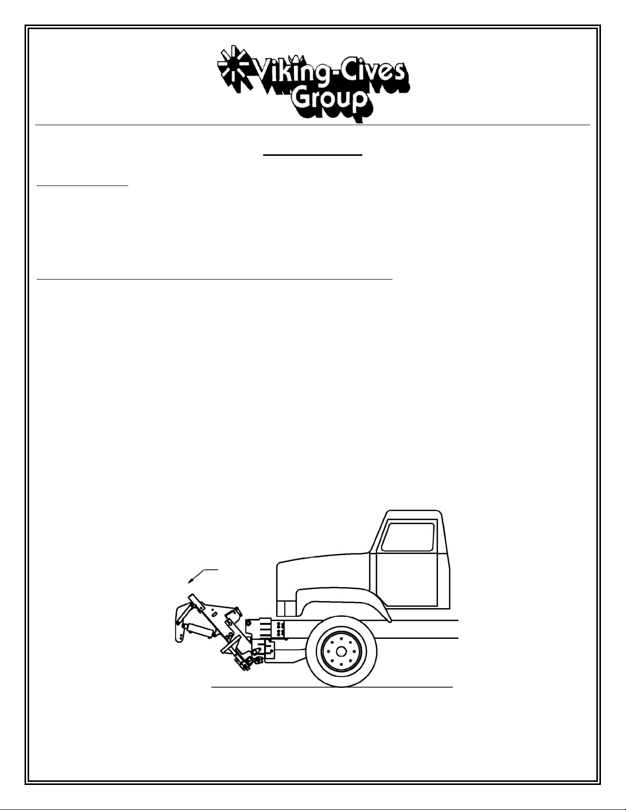
ATTACHMENT TO PRIME MOVER
The following instructions will aid in guiding you through the steps required to properly install your Viking-Cives Plow
Harness/Hitch to your chassis. While the exact installation may change slightly due to variations among the different chassis makes
and models, the basic steps required to complete are the same.
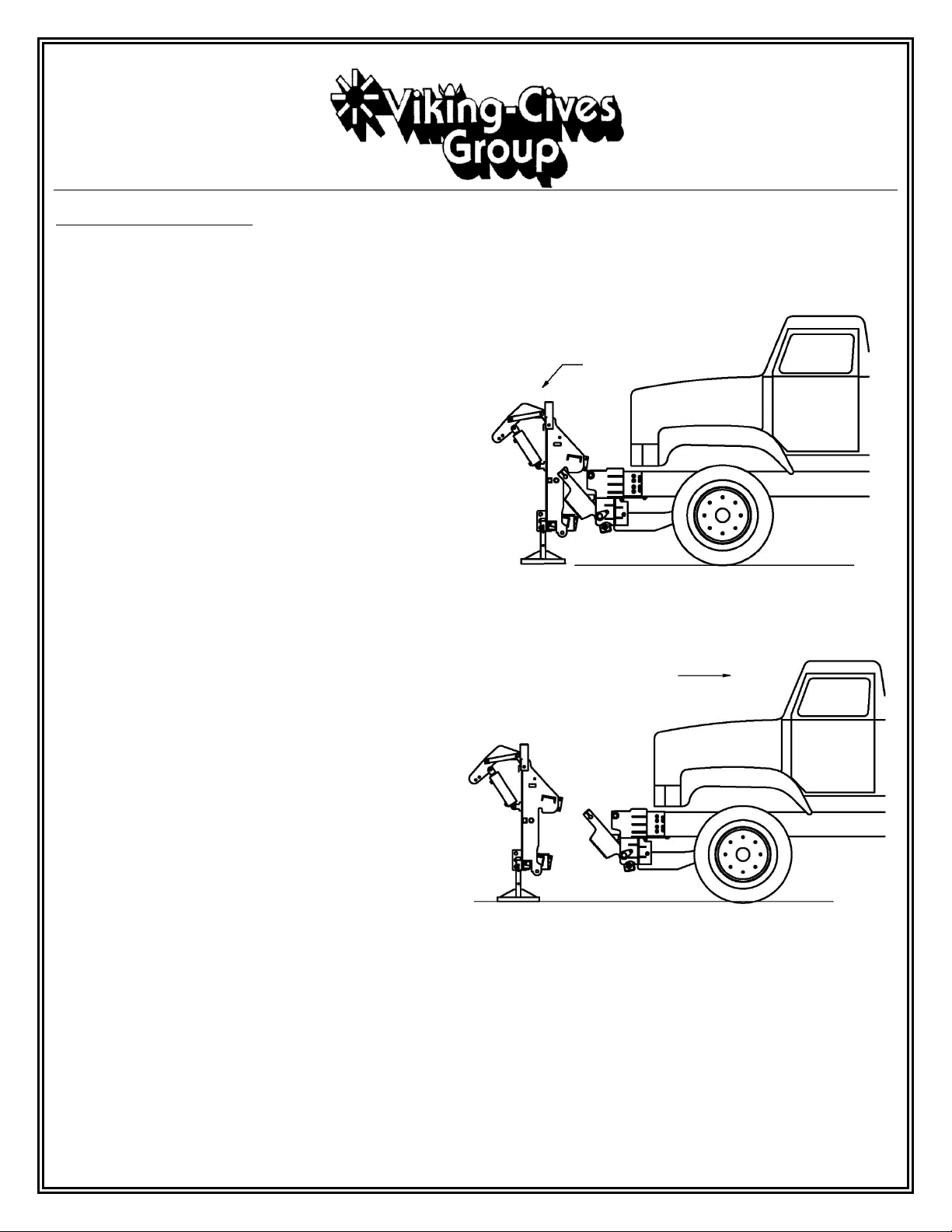
Chassis Preparation
1. Cover the chassis hood and fenders with a fire-resistant blanket/tarp to help protect paint from damage during the
installation process. Remove OEM supplied front bumper and set aside.
2. Visually inspect front of chassis for any obstacles and obvious points of interference that may need to be addressed (i.e.
starters, oil and/or fuel filters, radiator hoses, etc.).
3. If required, trim the front of the truck frame to keep the plow harness as close as possible to the chassis, reference tail
plate installation drawing specific to your vehicle for recommended locations. Additional clearance may be required for
front mounted hydraulic PTO/Pumps. Use a cutting torch and keep the cut as square as possible, clean and smooth all
rough edges with a grinder.
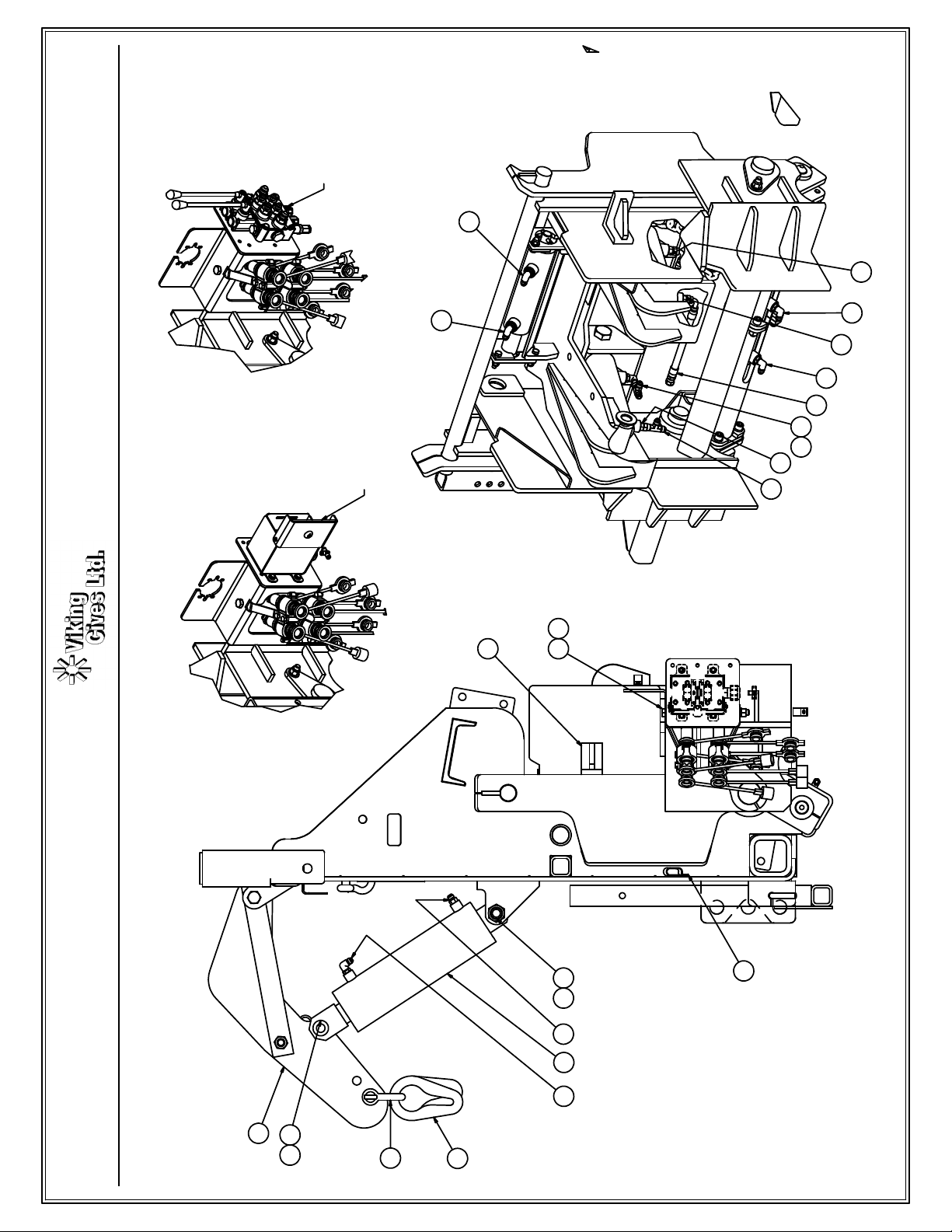
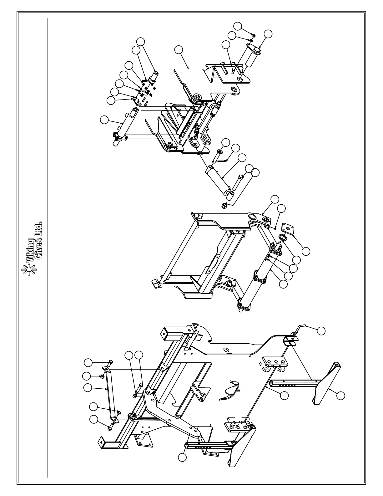
Tail Plate Installation
1. Install tail plates and front hitch as per the supplied assembly drawing for your specific model of tail plates.
When all conditions of installation have been met, the plow harness is ready to operate. The levers for controlling the plow harness
functions are located in the cab of the prime mover. WARNING: When the plow is being raised, lowered or reversed – STAND
CLEAR!