EKOVENT AB The right to changes is reserved 2022-06
3
Product management
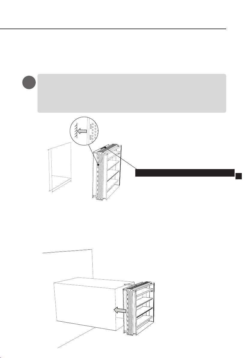
Transport
The re dampers must be transported to the
installation site using a truck or crane
with lifting fork.
Important !
To avoid damage the product must be
lifted, the product must not be pulled or
lowered hard against the surface.
Reception and inspection
of the delivery
Check the delivery for transport damage
and to ensure that it is copmplete as soon
as it arrives to the site. The approved
delivery is acknowledged by the
consignment note. Products with defects
may not be installed. Contact the supplier
immediatel
Storage
The storage of materials at the site should
be planned so that you get the minimum
possible internal transport. The re
dampers must protected against water and
always stored in a dry place. Furthermore,
they must be handled so that no
mechanical damage occurs to them.
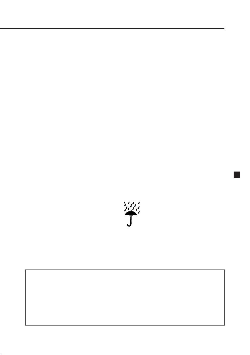
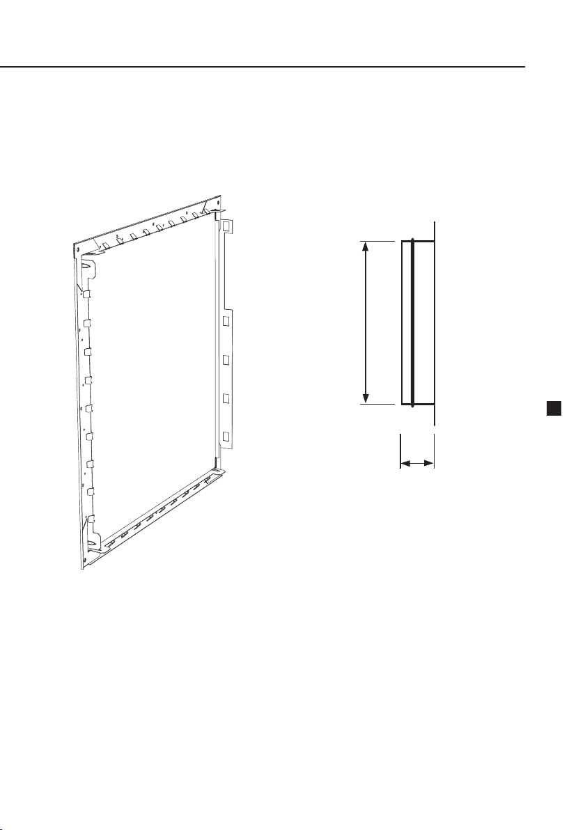
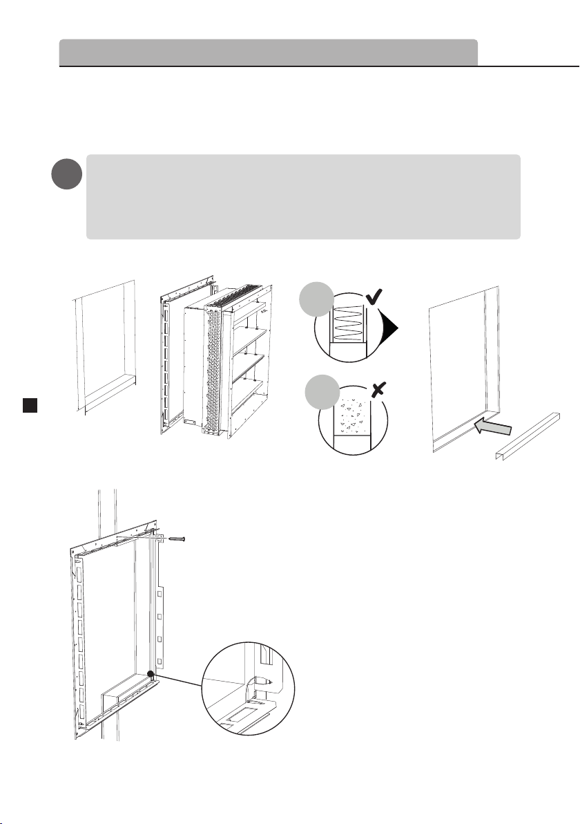
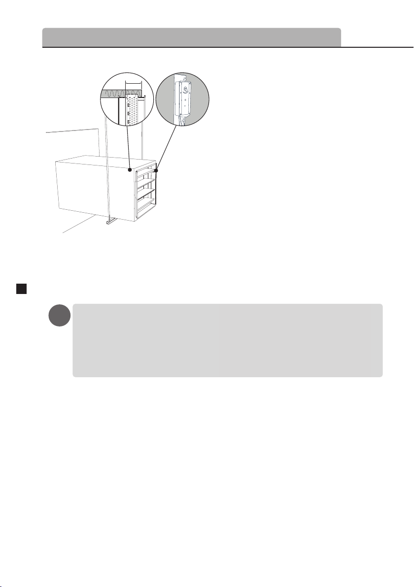
Mounting
Should not be installed outdoors or in
damp area spaces.
Commissioning
The re dampers must not be put into
operation until the complete installation
is in operational condition.
Responsibility and training
Assembly must be carried out by personnel
with training and experience in installation
of re damper products. Electrical
installation requires authorization.
Personnel must read through and
understand this instruction manual before
assembly. For questions, contact the
manufacturer or nearest dealer.
– Damage due to incorrect transport,
handling or storage.
– That the user has failed to inspect,
maintain and to a reasonable extent
take care of the equipment.
EKOVENT AB hereby disclaims all responsibility for:
– Personal injury or property damage as a
result of the product has been used in viola-
tion of instructions and specications in this
manual.
EKOVENT’s liability shall be limited to repair
or replacement of faulty equipment part.
Certication by: RISE Certifiering 0402
Product type description: EKO-RBG1, -R, -C
Approval number : C900166
Fire resistance class: EI 60 (ve i< >o, ho i< >o) S