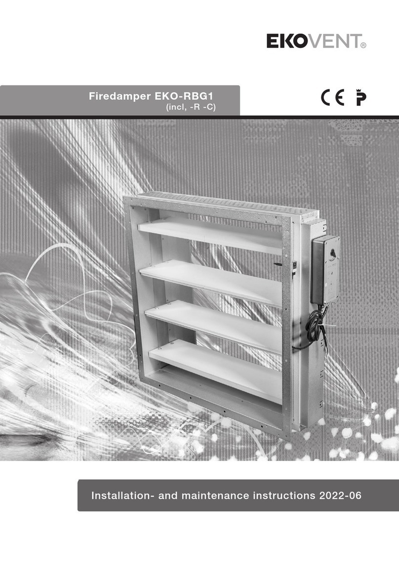
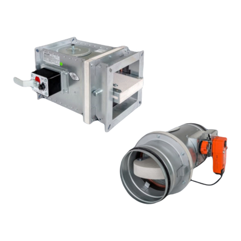
EKOVENT EKO-SRBG1 User manual

Installation- and maintenance instructions 2022-03
Fire damper EKO-SRBG1 & SRBG2
(incl, -R -C)

EKOVENT AB The right to changes is reserved 2022-03
2
Table of contents
Installation- and maintenance instructions
Product management.................................3
General assembly.......................................4
Mounting accessories ................................5
Owner of manufacturing site: EKOVENT AB, Vellinge
Certication by RISE Certifiering 0402
Product type description: EKO-SRBG1, -R, -C EKO-SRBG2, -R, -C
Approval number : SC0847-13 SC0407-13
Fire resistance class: EI 60 (ve i< >o, ho i< >o) S EI 60 (ve i< >o, ho i< >o) S
EI 120 (ve i< >o, ho i< >o) S
Assembly instructions .......................... 6-12
Operation and maintenance.....................13
Declaration of Performance................ 14-15

EKOVENT AB The right to changes is reserved 2022-03
3
Product management
Transport
The re dampers must be transported to
the installation site using a truck or crane
with lifting fork.
Important!
To avoid damage the product must be
lifted, the product must not be pulled or
lowered hard against the surface.
Reception and inspection of the
delivery
Check the delivery for transport damage
and to ensure that it is copmplete
as soon as it arrives to the site. The
approved delivery is acknowledged by the
consignment note. Products with defects
may not be installed. Contact the supplier
immediatel
Storage
The storage of materials at the site should
be planned so that you get the minimum
possible internal transport. The re
dampers must be protected against water
and always stored in a dry place.
Furthermore, they must be handled so that
no mechanical damage occurs to them.
Mounting
Should not be installed outdoors or in
damp area spaces.
Commissioning
The re dampers must not be put into
operation until the complete installation
is in operational condition.
Responsibility and training
Assembly must be carried out by personnel
with training and experience in installation
of re damper products. Electrical
installation requires authorization.
Personnel must read through and
understand this instruction manual before
assembly. For questions, contact the
manufacturer or nearest dealer.
– Damage due to incorrect transport,
handling or storage.
– That the user has failed to inspect,
maintain and to a reasonable extent
take care of the equipment.
EKOVENT AB hereby disclaims all responsibility for:
– Personal injury or property damage as a
result of the product has been used in viola-
tion of instructions and specications in this
manual.
EKOVENT’s liability shall be limited to repair
or replacement of faulty equipment part.

EKOVENT AB The right to changes is reserved 2022-03
4
Mounting
For the P and CE marking to apply assembly
must always be carried out according to the
supplied assembly instructions. The facility
must be equipped with a smoke detector
which indicates alarm and which activates
closing the re damper. The facility must
be connected to a monitoring system.
Mounting device for xing dampers in the
wall/oor is included in the damper delivery.
At assembly, the following minimum
dimensions must be taken into account:
– Minimum distance between dampers:
200 mm
– Minimum distance to wall/oor: 75 mm
Electrical connection
Electrical connection must be carried out
by an authorized person according to
drawings and current wiring diagram.
Wiring diagram EKO-SRBG1
Wiring diagram EKO-SRBG1-C
Wiring diagram EKO-SRBG1-R
Indikeringsdiod
Indicator diode
Pressure transmitter
Actuator
Connecting according to
the supplier’s instruction
Installation- and maintenance instructions

EKOVENT AB The right to changes is reserved 2022-03
5
Used at duct size Ød +55 mm.
Mounting accessories
Installation kit EKO-MOV*Flexible wall sleeve EKO-GIS
* Included in EKO-SRBG1 delivery
Duct bracket x 4
Only when mounting WITHOUT
wall damper caulking
Damper bracket x 4
Only for SRBG2
Extension adapter EKO-FNS
with wire mesh grille
Used for EKO-SRBG1 250–400 mm and for
all sizes when mounting to sleeve in wall.
Wire mesh grille EKO-NRS
Used for EKO-SRBG1 100–250 mm

EKOVENT AB The right to changes is reserved 2022-03
6
Installation- and maintenance instructions
Installation instructions – Installation on building part
Installation WITHOUT wall to damper caulking
i
Ød +10 mm
1
• Supporting construction, exible wall of plasterboard or
equivalent with re resistance EI 60.
• Supporting construction, wall or oor of concrete, brick or aerated con- crete with
re resistance EI 60
Wall opening for re damper installation:
Duct size Ød +10 mm.
x4
!
x4
!
SRBG2
x4
!
!x4
2
SRBG1
SRBG2
x4
!
!x4
x4
!
x4
!

EKOVENT AB The right to changes is reserved 2022-03
7
=
=
3
Seal with re protection sealant between
damper and wall and around the re
damper edge. Attach the re damper to the
building part. Use screws that ensure good
attachment.
Note! The re damper can be mounted
with damper shaft in any position.
4
Attach the duct to the damper with self-
drilling screws (maximum length 12 mm) or
pop rivets.
Important! Check that the movement of
the damper blades is not obstructed.
Ø 10 mm
5
Mount the thermal sensor with sensor
in the air stream.
Important! Check that the sensor
locationdoes not obstruct the movement of
the damper blade.
i
• Suspension device for dampers and ducts must correspond to the perforated re
technical class of the building part.
• Step 5 applies only to SRBG2.
i

EKOVENT AB The right to changes is reserved 2022-03
8
Installation- and maintenance instructions
A
B
Installation instructions – Installation on building part
Installation WITH wall damper caulking
i
A Supporting construction, exible wall of plasterboard or equvalent with re
resistance EI 60/EI 120.
B Supporting construction, wall/ cealing or oor of concrete, brick or concrete block
with re resistance EI 60/ EI 120.
Ød +55 mm
12
Wall opening for re damper installation:
Duct size Ød +55 mm.
x4
!
x4
!
SRBG2
x4
!
!x4
3
SRBG1
SRBG2
x4
!
!x4
x4
!
x4
!

EKOVENT AB The right to changes is reserved 2022-03
9
=
=
4
Seal with re protection sealant between
damper and wall and around the re
damper edge. Attach the re damper to the
building part. Use screws that ensure good
attachment.
Note! The re damper can be mounted
with damper shaft in any position.
5
Attach the duct to the damper with self-
drilling screws (maximum length 12 mm) or
pop rivets.
Important! Check that the movement of
the damper blades is not obstructed.
6
Use damper caulking between duct and wall EKO-KER or corresponding.
Seal with re protection sealant.

EKOVENT AB The right to changes is reserved 2022-03
10
Installation- and maintenance instructions
Ø 10 mm
7
Mount the thermal sensor with sensor in the air stream.
Important! Check that the sensor location does not obstruct the movement
of the damper blade.
8
Use screws that ensure good attachment.
Important! Check that the movement of the damper blade
is not obstructed.
i
• Suspension device for dampers and ducts must correspond to the perforated re
technical class of the building part.
• Step 7 applies only to SRBG2.
i

EKOVENT AB The right to changes is reserved 2022-03
11
Ø 10 mm
Installation in duct
• Supporting construction, wall or oor with re resistance EI 60.
1
Note! The re damper can be mounted with damper shaft in any position.
Attach the duct to the damper with self-
drilling screws (maximum length 12 mm) or
pop rivets.
Important! Check that the movement of
the damper blades is not obstructed.
Mount the thermal sensor with sensor
in the air stream.
Important! Check that the sensor
location does not obstruct the movement
of the damper blade.
2
i
• The following applies only to SRBG2.
i

EKOVENT AB The right to changes is reserved 2022-03
12
Installation- and maintenance instructions
3
Insultaion of the ventilation duct must be done in accordance with general regulations.
NOTE! The insulation does not need to cover the damper.
• Insulation of the ventilation duct must be carried out according to ISBN: 978-91-
633-1723-1 corresponding to it the building part’s re resistance class.
• Suspension device for dampers and ducts must correspond to the perforated
re technical class of the building part.
• Fireproong is carried out according to an approved method that meets the re
resistance class for example EKO-KER, EKO-GIS and re protection sealant.
i

EKOVENT AB The right to changes is reserved 2022-03
13
Maintenance
External and internal control
Interval: At least every 3 years.
Check for damage and function:
• Wiring to actuators.
• Limit switches and smoke detectors
• The damper casing must be free of
foreign matter details that can prevent
movement of the damper blade.
• Actuator attachment.
• Damper blade and sealing strip.
• The corrosion protection.
Function control
Automatic function check
Automatic function check must be perfor-
med at intervals of 48 hours.Occurring error
functions appear in the display.
Manual function check
See separate instructions for the
monitoring system.
Check that:
• the re damper is fully open during
operation
• the re damper closes completely
• the re damper opens fully
• the re damper closes completely in
the event of a power failure.
Cleaning
Preventive maintenance of the damper
shall be made according to the facility’s
needs. Clean up damper blade and damper
body inside with brush, vacuum cleaner or
dry cloth.
Note!
Water or other liquids must not be used.
Note!
After checking, the re damper must be left
in normal working mode.
Warning!
Never put your hands inside the damper
when closes. Risk of crushing injuries.
Spare parts list
Actuator, see type designation on the
actuator.
Maintenance

EKOVENT AB The right to changes is reserved 2022-03
14
Installation- and maintenance instructions
DECLARATION OF PERFORMANCE
Fire Damper SRBG1
Type and batch number according to product label.
Fire damper to be used in conjunction with re separating elements to maintain re compartmentation of at least 60 min according to EN 15650.2010.
EKOVENT AB, Mejselgatan 7, 23532 Vellinge, www.ekovent.se
Certicate:
SP Technical Research Institute of Sweden, nr 0402, has performed type testing, initial inspection of the manufacturing plant and
factory production control (FPC) under system 1
EC Certicate of Conformity 0402-CPR-SC0845-13
The performance of SRBG1 is in conformity with the declared performance above.
This declaration of performance is issued under the sole responsibility of EKOVENT AB.
Signed for and on behalf of the manufacturer by:
Vellinge 2018-01-12, Michael Brändström R&D Manager

EKOVENT AB The right to changes is reserved 2022-03
15
DECLARATION OF PERFORMANCE
Fire Damper SRBG2
Type and batch number according to product label.
Fire damper to be used in conjunction with re separating elements to maintain re compartmentation of at least 120 min according to EN 15650.2010.
EKOVENT AB, Mejselgatan 7, 23532 Vellinge, www.ekovent.se
Certicate:
SP Technical Research Institute of Sweden, nr 0402, has performed type testing, initial inspection of the manufacturing
plant and factory production control (FPC) under system 1.
EC Certicate of Conformity No 0402-CPR-SC0397-13.
The performance of SRBG2 is in conformity with the declared performance above.
This declaration of performance is issued under the sole responsibility of EKOVENT AB.
Signed for and on behalf of the manufacturer by:
Vellinge 2018-06-19, Michael Brändström R&D Manager.

HEAD OFFICE
Mejselgatan 7, 235 32 Vellinge
Tel +46 40 42 16 00
www.ekovent.se [email protected]
REGIONAL OFFICE GÖTEBORG
Boråsvägen 5, 435 31 Mölnlycke
Tel +46 31 23 07 40
REGIONAL OFFICE STOCKHOLM
Vallgatan 9, 170 67 Solna
Tel +46 8 508 613 00
This manual suits for next models
7
Table of contents
Other EKOVENT Fire And Smoke Damper manuals