Bedienungsanleitung
Manual
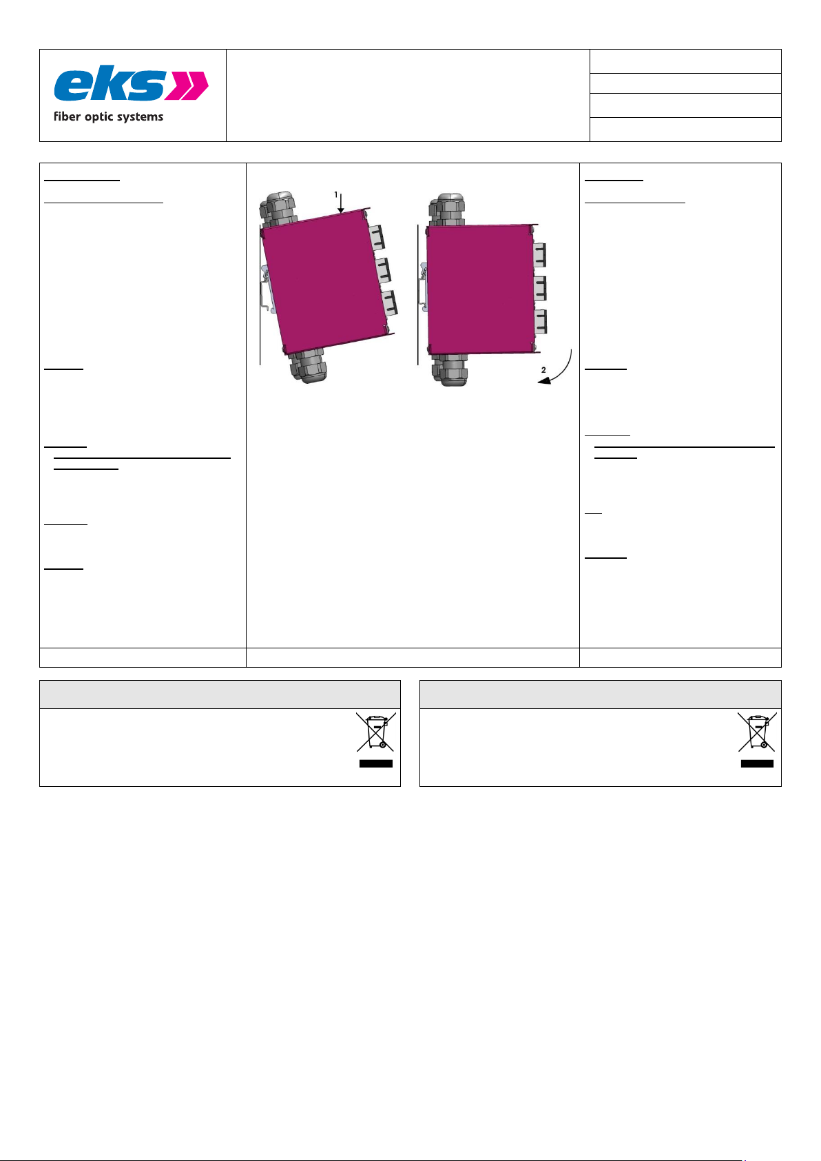
Schritt 12
Montage auf Tragschiene:. Zur Montage
(siehe Bild rechts) rasten Sie bitte den
FIMP XL-E an der Oberseite in die DIN
Tragschiene ein und drücken dann gegen
die Federkraft nach unten (1) und
anschließend zur Montageplatte hin (2).
Das System FIMP XL-E verriegelt wie im
Bild rechts dargestellt.
Zur Demontage drücken Sie das Gehäuse
nach unten (überwinden Sie die Federkraft
des Hutschienenclips). Ziehen Sie dann
das Gerät zu sich und entnehmen es aus
der Tragschiene.
Achtung: Benutzen Sie nur die zugehörigen
LWL-Anschlussstecker. Wir weisen
ausdrücklich daraufhin, dass der Anschluss
mit falschen Steckverbindern Schäden an
den optischen Anschlüssen hervorrufen
kann!
Achtung:
Sehen Sie nicht in das Faserende oder
die Kupplung! Das gebündelte und
abhängig von der Wellenlänge sichtbare
oder unsichtbare Licht kann zu
Augenschäden führen!
Benutzen Sie die beigefügten Schutzstopfen,
um die Kupplungen vor Verunreinigungen
und Staub zu schützen.
Achtung: Knicken Sie das LWL-Kabel nicht
zu stark und beachten Sie den Biegeradius
des Kabels. Andernfalls kann das Kabel
beschädigt werden und/oder die
Kommunikation zwischen den
angeschlossenenen Geräten nicht mehr
gewährleistet werden.
Step 12
Mounting on DIN-Rail: For mounting (see
picture on the left), please snap the
FIMP XL-E on the top side into the DIN
rail and then press down against the
spring force (1) and then towards the
mounting plate (2). The FIMP XL-E
system locks as shown in the picture on
the right.
To remove, press the housing down
(overcome the spring force of the DIN
rail clip), then pull the device towards
you and remove it from the mounting
rail.
Attention: Use only the appropriate fiber
optic connectors. We expressly point out
that the use of incorrect components can
cause damage to the optical connections!
Attention:
Do not stare into the optical fiber or the
coupling. Visible or non-visible light
(depending on its wave-length) of the
optical transmitter can cause damage to
the eyes!
Use the enclosed protective plugs to protect
the couplings from dirt and dust.
Attention: Do not bend the fiber optic cable
too much and observe the bending radius
of the cable. Otherwise the cable can be
damaged and/or communication between
the connected devices can no longer be
guaranteed.
Die Geräte dürfen nicht über den normalen Hausmüll entsorgt werden,
sondern können bei eks Engel FOS GmbH & Co. KG entsorgt werden.
WEEE-Kennzeichnung: DE 900 53 255
The units must not be disposed with normal household waste but
can be returned to eks Engel FOS GmbH & Co. KG for disposal.
WEEE-identification: DE 900 53 255