eks pe-light-S-COAX User manual

Bedienungsanleitung
Manual
MAN_PEL-2-COAX
Version:
26.01.2021
Freigabe:
U.A.
Seite 2 von 9
Allgemeine Hinweise / General information
Diese Anleitung enthält wichtige Anmerkungen und Warnungen, deren
Nichtbeachtung zu ernsthaften Personen- oder Anlagenschäden führen kann.
Bitte lesen Sie die Anleitung vor Inbetriebnahme der Geräte aufmerksam durch.
Ordnungsgemäßer Transport, korrekte Lagerung und Installation sowie sorgfältige
Bedienung und Instandhaltung sind entscheidend für den sicheren Betrieb.
Bestimmungsgemäße Verwendung
►Die Geräte dürfen nur wie in der Anleitung beschrieben verwendet werden.
►Sie dürfen nur unbeschädigt und unter den angegebenen Umweltbedingungen
eingesetzt werden.
►In den Geräten befinden sich keine durch den Benutzer wartbaren
Komponenten.
Personalanforderungen
►Die Installation und Inbetriebnahme der Geräte darf nur durch technisch
geschultes Personal erfolgen, das sich mit dieser Bedienungsanleitung vertraut
gemacht hat.
►Alle Arbeiten an elektrischen Anlagen dürfen außerdem nur durch eine
Elektrofachkraft oder unter deren Leitung oder Aufsicht durchgeführt werden.
►Anzuwendende lokale und nationale Sicherheitsbedingungen müssen jederzeit
eingehalten werden.
Spannungsversorgung
►Die Geräte der PE-LIGHT Produktfamilie wurden für den direkten Betrieb mit
einer Netzspannung von 230V / 50Hz designt.
►Sie dürfen nur durch EN 62368-1 / VDE0805-1 konforme Spannungen versorgt
werden.
►Um den Spannungsabfall auf der Anschlussleitung zum Laternenmast zu
minimieren, ist ein entsprechender Kabelquerschnitt zu verwenden. Die
Anschlussklemmen und Kabeldurchführungen auf der Unterseite sind daher für
Querschnitte bis 25 mm² ausgelegt.
►Für die Zuleitung des Switches ist ein Kabelquerschnitt von mindestens 1mm²
zu verwenden. Alle Anschlussleitungen müssen der DIN EN 60332
entsprechen.
►Nehmen Sie ausschließlich unbeschädigte Teile/Geräte in Betrieb.
►Das Gerät beinhaltet keine Servicebauteile. Bei Funktionsstörungen oder
Beschädigungen schalten Sie die Versorgungsspannung ab und senden Sie
das Gerät zur Überprüfung an die eks Engel FOS GmbH & Co. KG.
Gehäuse
►Das Öffnen des Gehäuses bleibt ausschließlich einem autorisierten Techniker
der eks Engel FOS GmbH & Co. KG vorbehalten.
Gehäusetemperatur
►Wenn die Geräte bei Umgebungstemperaturen von über 50 °C betrieben
werden, kann die Temperatur der Geräte mehr als 70 °C betragen.
►Die Geräte müssen dann in einem abgeschlossenen Bereich betrieben werden,
der nur dem Service-Personal zugänglich ist oder von Benutzern, die über die
Gründe dieser Einschränkung und über notwendige Vorkehrungen beim
Betrieb über 50 °C informiert wurden.
Sicherheit von Lasereinrichtungen
►Die Geräte enthalten LED- oder LASER-Komponenten nach IEC 60825-
1:2014: Klasse 1 Laser/LED-Produkt.
Warnung!
►Nicht mit optischen Instrumenten (z.B. Linsen,
Mikroskop) in den Strahl der optischen
Transceiver sehen! Missachtung dieser Warnung
kann zu Augenschäden führen.
►Sehen Sie nicht in den optischen Sender. Das
gebündelte und abhängig von der Wellenlänge
sichtbare oder unsichtbare Licht kann zu
Augenschäden führen!
This manual contains important notes and warnings that could lead to serious
personal and properly damage, if ignored. Please read the manual carefully prior
to commissioning the devices. Correct transport, storage and installation, careful
handling and maintenance of the components are critical for a safe operation.
Intended use
►The units may only be operated as described in this manual.
►They may only be used undamaged and according to the specified ambient
conditions.
►The devices do not contain any components that must be maintained by the
customer
Personnel requirements
►Installation and commissioning of the devices may only be performed by
technically trained personnel who are familiar with this operating manual.
►All work on electrical systems may only be carried out by qualified electricians
or under their direction or supervision.
►Applicable local and national safety requirements must be complied with at all
times
Power Supply
►The PE-LIGHT product family was designed for the direct operation with a
main voltage of 230V / 50Hz.
►They may only be fed by voltages compliant with IEC62368-1 / VDE0805-1.
►In order to minimize the voltage drop on the connecting cable to the lantern
pole, an appropriate cable cross section must be used. The connection
terminals and cable bushings on the underside are therefore designed for
cross-sections of up to 25 mm².
►The cross-section of the cable for the supply lines to the switch have to be at
least 1mm². All the cables to the switch have to comply with DIN EN 60332.
►Only put undamaged parts/devices into operation.
►The device does not contain any service components. In case of malfunctions
or damages, switch off the supply voltage and return the device for an
inspection to eks Engel FOS GmbH & Co. KG.
Enclosure
►Opening the housing remains the sole responsibility of an authorized technician
of eks Engel FOS GmbH & Co. KG.
Case temperature
►If the devices are operated at ambient temperatures above 50 °C, their
temperature may exceed 70 °C.
►The units must then be operated in a closed area accessible only to service
personnel or by users who have been informed about the reasons for this
restriction and about the necessary precautions for operation above 50 °C.
Safety of laser products
►The devices of the product contain LED / laser components in accordance with
IEC 60825-1:2014: Class 1 laser/LED-product.
Warning!
►Do not look into in the beam of the optical
transceivers with optical instruments (eg, lenses,
microscope)! Ignoring this warning may result in
eye damage.
►Do not look into the optical transmitter. The
bundled and - dependent on the wavelength -
visible or invisible light can cause eye damage.

Bedienungsanleitung
Manual
MAN_PEL-2-COAX
Version:
26.01.2021
Freigabe:
U.A.
Seite 3 von 9
CE-Konformität CE / Conformity
Die Geräte stimmen gemäß den Bestimmungen der EU-Richtlinie 2014/30/EU
„RICHTLINIE …über die elektromagnetische Verträglichkeit“ mit den
folgenden Normen und normativen Dokumenten in den aktuellen Fassungen
überein:
DIN EN 55032: Einrichtungen der Informationstechnik Funkstör-
2016-02 –Klasse A eigenschaften –Grenzwerte und Messverfahren
DIN EN 61000-6-2: Elektromagnetische Verträglichkeit (EMV) –Teil 6-2:
2005 Fachgrundnormen –Störfestigkeit für Industriebereiche
The devices of the agree according to the provisions of EU Directive 2014/30/ EU
"DIRECTIVE ... relating to electromagnetic compatibility" with the following
standards and normative documents in the currently valid version:
DIN EN 55032: Information technology equipment - Radio disturbance
2016-02 - Class A characteristics - Limits and methods of measurement
DIN EN 61000-6-2: Electromagnetic compatibility (EMC) –Part 6-2: Generic
2005 standards - Immunity for industrial environments
Entsorgungshinweis / Disposal notes
Die Geräte dürfen nicht mit dem normalen Hausmüll entsorgt werden,
sie können bei der eks Engel FOS GmbH & Co. KG entsorgt werden.
WEEE-Kennzeichnung: DE 900 53 255
The units must not be disposed with normal household waste but
can be returned to eks Engel FOS GmbH & Co. KG for disposal.
WEEE-identification: DE 900 53 255
Systembeschreibung / System description
Die Geräte der pe-light-COAX Produktfamilie sind industrielle Komplettlösungen
für den Einbau in Lichtmasten aus Stahl mit den folgenden Normen in den
aktuellen Fassungen:
DIN EN 40-5 Anforderungen für Lichtmasten aus Stahl
DIN 49778 Lichtmaste, Gerätesteg mit Schiebemuttern
Der Einbau des pe-light-COAX erfolgt in einem Laternenmast mit dem
Innendurchmesser von ≥100 mm und einem Türausschnitt von ≥400x85 mm.
pe-light-COAX gibt es in einer Variante mit einem RJ45 Ethernet Anschluss und in
einer Variante mit zusätzlichem Gigabit Ethernet-PoE Switch wovon
3 x M12 GB Ethernet Ports frei verfügbar sind.
The devices of the pe-light-COAX product family are industrial complete solutions
for the installation in light poles made of steel with the following standards as
amended today:
DIN EN 40-5 Requirements for steel lighting columns
DIN 49778 Lighting columns, brackets with sliding nuts for mounting of devices
The pe-light-COAX is installed in a lantern pole with the inside diameter of at least
≥100 mm and a door section of ≥400x85 mm.
pe-light-COAX is available as a version with one single RJ 45 ethernet port and in
a version with additional GB ethernet-PoE Switcht. Three M12 GB ethernet ports
can be utilized by the enduser.
Vorbereitung / Preparation
Vor dem Öffnen des Gehäuses Spannungsfreiheit herstellen! / Make sure there is no voltage before opening the housing!
Geschlossen / closed
Öffnen / opening
Mast offen / open pole
Schrauben lösen / release screws
Deckel schräg anheben / open lid
Deckel abheben / remove lid
Obere Befestigungsschraube /
upper mounting screw
Untere Befestigungsschraube /
lower mounting screw
Masterdungsschraube /
earth bolt

Bedienungsanleitung
Manual
MAN_PEL-2-COAX
Version:
26.01.2021
Freigabe:
U.A.
Seite 4 von 9
Klemmenblock entriegeln und abheben /
Release screw terminal and pick up
Schraube des Netzteils lösen /
Release screw of the power supply
Netzteil nach unten schieben entnehmen /
push power supply downwards and remove it
Isolierscheibe abheben / remove insulating plate
Zugentlastung lösen / release strain-relief
Kabeleinsatz abheben / remove cable break
Koaxkabel anschließen /
connect COAX cable
Isolierschiebe wieder einlegen /
reinsert insulating plate
Netzteil einschieben und fixieren /
place power supply and tighten the screw
Klemmenblock aufrasten / mount screw terminal
Netzanschlusskabel anschließen / connect mains
Zugentlastung montieren / mount strain-relief

Bedienungsanleitung
Manual
MAN_PEL-2-COAX
Version:
26.01.2021
Freigabe:
U.A.
Seite 5 von 9
Deckel schräg einsetzen / insert lid
Deckel festschrauben / fix lid
Verbindungskabel vom internen COAX Medienwandler zum Switch in einen der vier M12 GB Ethernet Ports des Switches einschrauben.
Die drei freibleibenden M12 Anschlüsse können von Kundenapplikationen genutzt werden.
Connect the ethernet cable coming from the internal COAX converter to one of the four M12 GB Ethernet ports of the switch.
The three remaining M12 ports can be utilized by the end-user.

Bedienungsanleitung
Manual
MAN_PEL-2-COAX
Version:
26.01.2021
Freigabe:
U.A.
Seite 6 von 9
Sicherheitshinweis: pe-light-S-COAX ist nur für Metallmasten nach DIN EN 40 mit Türausführung nach DIN 48778 geeignet!
Security advice: pe-light-S-COAX is only suitable for metal pole according to DIN EN 40 with door according to DIN 48778!
Erdungskabel anschließen / pe-light-COAX in Türöffnung setzen / Gehäuse mit beiden Befestigungsschrauben im Mast fixieren
Connect earth wire insert pe-light-COAX into the pole fasten the housing with upper and lower fixing screw
Abmessungen / Dimensions
Masteinbau / Pole installation

Bedienungsanleitung
Manual
MAN_PEL-2-COAX
Version:
26.01.2021
Freigabe:
U.A.
Seite 7 von 9
Technische Daten / Technical specifications
Bestellinformationen / Ordering information
Ausführung Type
blue
green
yellow
red
PEL-S-COAX mit
Gigabit PoE Switch managed
10008128
Allgemeine Angaben / General information
Versorgungsspannung
Operating voltage
230 VAC / 50 / 60 Hz
Leistungsaufnahme
Power consumption
Max. 200 W
Potentialtrennung
Potential separation
2500 VDC
Sicherung
Fuse
Min. 40A2s, PoE-Switch: 2 A (z.B. Littelfuse FLM)
Min. 40A2s, PoE-Switch: 2 A (e.g. Littelfuse FLM)
Anschlussklemmen
Clamp
1,5 mm² bis 25 mm²
1.5 mm² to 25 mm²
Befestigungsmöglichkeit
Mounting options
Hakenbefestigung im Laternenmast
Hook fastening in lantern pole
Betriebstemperatur
Operating temperature
-20 °C bis +60 °C
-20 °C to +60 °C
Lagertemperatur
Storage temperature
-30 °C bis +80 °C
-30 °C to +80 °C
Luftfeuchtigkeit
Humidity
10-95% rHd nicht kondensierend
10-95% rHd non-condensing
EMV
EMC
DIN EN 55032:2016-02 - Klasse A / DIN EN 61000-6-2:2005
DIN EN 55032:2016-02 - Class A / DIN EN 61000-6-2:2005
Gewicht
Weight
1540 g
Abmessungen B x H x T
Dimensions W x H x D
B: 82 mm, H: 84 mm, T: 369 mm
W: 82 mm, H: 84 mm, D: 369 mm
Gehäuse / Schutzart
Case / Protection class
Polycarbonat (PC GF 6-7) / IP54
Technische Änderungen vorbehalten. Für Irrtümer und Druckfehler keine Haftung. © eks Engel FOS GmbH & Co. KG
Reserve technical changes. No liability is accepted for errors and printing errors. © eks Engel FOS GmbH & Co. KG

Overview
브라켓 홀
DC 전원 어댑터
브라켓 홀
Join버튼
상태표시등
PoE ON/OFF스위치
(ECP-2601T전용)
This device is a High-Speed, long distance Ethernet & PoE extender
that makes possible to transmit the Ethernet signal up to 2.4Km and
PoEup to1.2Km viaCoax (or UTP,2-wire)cables indifferent situations.
It is cost-effective and time saving solution to migrate existing analog
system to IP based system since this device supports easy installation
utilizing the existingcable.
With long distance transmission feature, the device makes to
overcome 100 meters distance limitation easily and reduces the
constructioncostsignificantlycomparedwithfiberopticconfiguration.
[Rev.1.0]
Package
Features
Ethernet over Coax communication following IEEE1901 Standard
Data + Power over Coax cable (or UTP, 2-Wire)
Data distance upto 2.4Km
PoE distance up to1.2Km
Max. 95MbpsBandwidth
(270Mbps between Intercoax 2 series models)
10/100 Full Duplex
128bit AES networkencryption
Supports Multi-connection (Daisy chain, Star,etc.)
PoE, PoE+, Extra PoE (Max. 60W output)
ECP-2601T (Transmitter)
ECP-2601R (Receiver) Bracket Quick Start
Guide
SupportsUTP,Telephone(2Pairs),2-Wirecablecommunication
(Using BTESeries)
LED Indication (Data, Power, Link,PoE)
Plug &Play
Hardware Overview
Surge Protection
Support PoE+ Input (25.5W) from PSE devices –ECP-2601ROnly
Slim design
Installation Guide
LEDIndicators
1.
SettheIPaddressonthecamerafollowingtheinstructionmanual
of thecamera.
IfthecameraIPisautomaticallyassigned(DHCP,etc.),thereisno
need to set the camera IP separately.
2.
Connect BNC of the coaxial cable toeach
Transmitter/Receiver
.
3.
Connect 56V DC power to
Transmitter/Receiver
first and then to
AC outlet.
Receiver
can be powered by PoE Switch Device (PoE+ PD
Supported) but for safe working, it recommeded to use 56VDC
Powersupplyon
Receiver
.WhenusingbothPoEswitchDeviceand
power supply at the same time, power supply works preferentially.
In case of 7W camera, the device supports long distance PoE
transmission up to 1,200m over RG6 coaxial cable.
PoEtransmissiondistancecanbevarieddepending on cabletype
and Camera’s power consumption(W).
4.
When they are connected without any problem, Power
/
Join Link
LED are on.
5.
Adhere the brackets in the package to
Transmitter/Receiver
and
then fix up theproducts.
6.
ConnecttheUTP(LAN)cablebetween
Receiver
andNVRfirstand
then between
Transmitter
and camera.
7.
Turn on the PoE switch on
Transmitter
for PoE IP camera and ifthe
camera is powered by a separate power source (not powered by
PoE output feature of the
Transmitter
), turn off the PoE switch on
Transmitter
.
Both
Transmitter/Receiver
send data and power together via BNC
connector.
Receiver
does not have PoE support so that it can send
data only viaRJ45.
8.
Ping test is recommended to confirm the whole network after
installation.
9.
Check the video signal on the monitor.
PoE ON/OFF Switch PoE-ON(ECP-2601T)
(ECP-2601T only) PD-AUX(ECP-2601R)
Data-Link
Join-Link
Power
Join
BracketHole
RJ45
Join Button
Status LED Indicator
PoE-ON
Bracket
PoE
ON OFF
ETHERNET
Left
Right
NOANALOG
CAMERA
BracketHole
DC Power Jack
Bracket
56V DC
Quick Start Guide
ECP-2601T /ECP-2601R
Pleasereadcarefullytheinstructionmanualbeforeuse.Depending
onthe model,the imageandthe actuallookof theproduct may vary.
Indicator Color Function
PoE-ON (Tx)
ON:PoESwitchOn(PoEOutput)
OFF : PoE Switch Off
PD-AUX (Rx)
ON : PoE Input or Powered by Transmitter
OFF : Powered by adapter
Data-Link
Blinking : Ethernet Data Act
Join-Link
ECP-Product Link
Power
56V DC Link

Applications
Specification
Thisdevicecomplieswithpart15ofthefccrules.Operationissubjecttothe
following two conditions:
(1)
Thisdevice maynotcause harmfulinterference,and
(2)
This device must accept any interference received including interference
thatmay cause undesired operation
AC/DC
Adapter(12V)
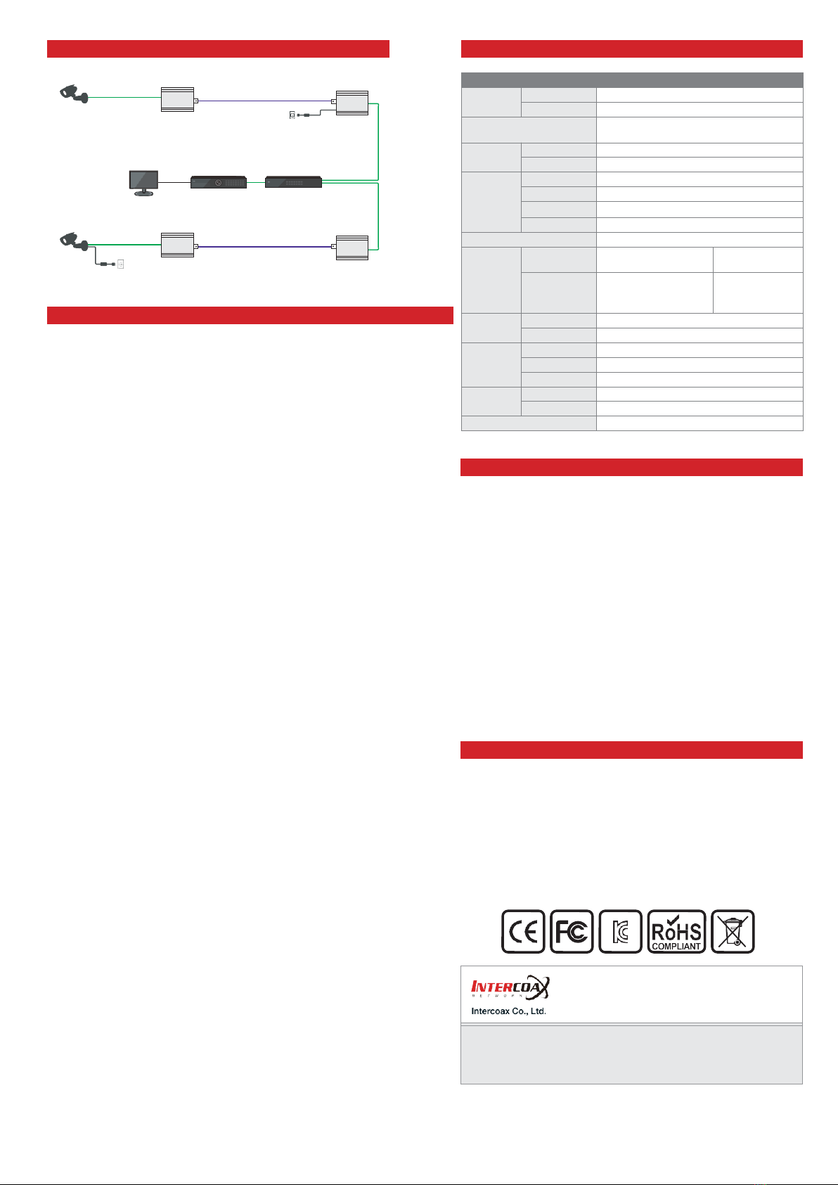
How to change the communication password (Coax/UTP/2-Wire)
All Intercoax EoC converters have the same password as factory
defaults setting value and can be used immediately when connecting
to the product (Plug & Play mode).
However, if a number of products are mixed in the same area or
the signal transmission line is in poor condition, the communication
passwords for each equipment (or group) can be set differently to
prevent cross-talk between thelines.
1.
Needed items for Joining
EoCConverters/Powersupply/ShortCable(Coax,UTP,2-Wire)/
Paper clip
2.
Product configuration
a.
ConnectEoCConverterswithCoaxcable(orUTP,2-Wire)and
power to the one of the converters up with power supply.
b.
Check if the Power LED on both devices is ON.
3.
Remove the existing password (Unjoining)
This process removes passwords that are entered as factory
defaults.
a.
Press the Join button on one of the connected products using a
paper clip until the Power LED turns off and on (Approximately
15 seconds)
b.
Remove the existing password bypressing the Join button on the
opposite product in the same way as above.
c.
Join LED will be turned off if the password on the devices is
removed correctly.
4.
Create New Password(Joining)
New password for communication between connected devices is
created and this will block the communication with other devices (or
group) which have a different password.
a.
Press the Join button for 2 seconds on one of the connected
product using a paper clip and the Join LED of the device will
flicker at a constant speed. (Stand-by mode)
b.
Press the Join button for 2 seconds on the opposite device in the
sameway asabove. Andthen, theJoin LEDofthe deviceflickers
at a constant speed and both devices restart at the same time.
c.
Then the Join-Link lights up and communications are resumed
between the products
5.
When adding new products in 1:N configuration to a group that
has already been joined. (Group Joining)
a.
Connect new device to the group which isalready joined. (using
T-BNC or Y-UTP coupler,Terminal block)
b.
Remove the password ofthe new device in thesame way asstep
‘3-a’.
c.
PressJoinbuttonontheoneofthedeviceoftheexistinggroup
for2secondsand JoinLEDflickersataconstantspeed.
d.
Press Join button on the newdevice for 2 seconds and new
device restarts
e.
Join-Linklightsup and communications are resumed between
the products.
Caution
Please install the device following the installation guide.
Do nottouch the device and cable with wet hands.
Keep away from moisture and shock.
Donotinstallnearanyheatsourcessuchasradiators,heatregisters,
stoves orother apparatus that produce heat.
Indoor useonly.
Do notuse for other purposes.
Do not disassemble or modify this device.
Do notputany sticker or paint on it.
Ifthisdeviceisdefectiveormalfunctioning,pleaseunplugthepower
adapterimmediately andcontact dealerorservice center.
Please use the rated power supply for the product.
Connect DC power to this device first and then to AC outlet.
Warranty
This device has passed the quality control and product inspection.
Please install and use according to the installation guide.
Thewarranty periodfor thisproductis24monthsfromthe date of
purchase.
Ifthis device isdefective ormalfunctioning, please unplug the power
adapter immediately and contact dealer or service center.
Any damages or breakage from user’s abuse, accident, modification
or natural disasters will not be covered manufacturer’s warranty.
10/100 Ethernet
PoE
CoaxialCable
PoE
Camera
ECP-2601T
56V DC/1.2A
PowerSupply
ECP-2601R
NVR
PoE Switch
10/100 Ethernet
CoaxialCable
Non-PoE IP
Camera
ECP-2601T
ECP-2601R
Please visit below website for more detailed information.
Web: http://www.intercoax.com Tel: +82. 31. 365. 3133~4
Model ECP-2601T ECP-2601R
Interface
Coax
1 x 75Ω BNC (Female)- Ethernetover Coax(B-LinX)
Ethernet
1xRJ45-10/100Base-TwithAuto-detectMDIX
Transmission Rate
95Mbps Full Duplex
(270Mbps between Intercoax devices)
Transmission
Distance
Ethernet
up to 2.4Km(RG-6)
PoE (PoC)
up to 1.2Km (RG-6
/
7W camera)
LED
Indication
Ethernet
1 x Data-Link (Yellow)
EoC
1 x Join-Link (Green)
Power
1 x Power On(Amber)
PoE
1 x PoE Out (Red)
Encryption
128-bit AES
Power
Input
B-Linx or DC12V~57V
PoE Switch or
DC12V~57V
PoE Output
IEEE802.3af(PoE),
IEEE802.3at (PoE+),
Extra PoE up to 60W
PoE Not Supported
PoC Only
Mechanical
Dimension
82.4(L) x 61.6(W) x 24(H)mm
Weight
77g
Environment
Operating Temp
-20 ~ 60°C
Storage Temp
-30 ~ 80°C
Relative Humidity
10% ~ 90%
Compliance
Certification
FCC, CE, KC
Surge Protection
IEC61000-4-54kV(1.2/50us),2kA(8/20us)
Optional Accessories
56VDC
/
1.2A External Power Supply
This manual suits for next models
1
Table of contents
Other eks Industrial Equipment manuals
Popular Industrial Equipment manuals by other brands

Noritz
Noritz NRC661 Series Instructional manual

Danfoss
Danfoss BOCK HRX CO2 T H Translation of the original instructions

SEW-Eurodrive
SEW-Eurodrive Spiroplan W operating instructions

Loveshaw
Loveshaw LITTLE DAVID LD7D/3 Parts and instruction manual

Mark 7
Mark 7 DecapSense 1050 Super instruction manual

SW-Stahl
SW-Stahl 26017L instruction manual