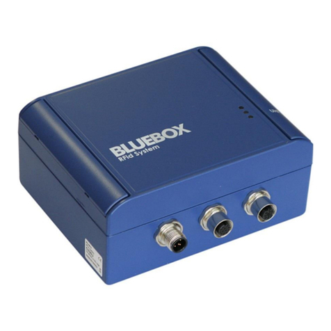
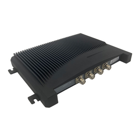
ELA SCIEL READER IP2 User manual

Specifications could be modified without any notification. Non-contractual document.
www.elainnovation.com Copyright © 2018 ELA Innovation
User Guide SCIEL
READER IP2 04B.docx
1/18
User guide
SCIEL READER IP2
Ref. SCIBT68B
Powerful “Active RFID gateway” for your Ethernet local network
Compact and robust aluminium housing dedicated for the industrial applications
Integrated PoE feature for the SCIEL READER IP2
Multiples IP protocols supported for the network management with your LAN network

Specifications could be modified without any notification. Non-contractual document.
www.elainnovation.com Copyright © 2018 ELA Innovation
User Guide SCIEL
READER IP2 04B.docx
2/18
TABLE OF CONTENTS
1MAIN SPECIFICATIONS...................................................................................................... 3
2PACKING INFORMATION.................................................................................................... 4
3PHYSICAL INFORMATION .................................................................................................. 5
3.1 ANTENNA CONNECTOR ........................................................................................................ 5
3.2 3 PINS TERMINAL BLOCK WIRING......................................................................................... 6
3.3 POWER SUPPLY AND POWER OVER ETHERNET (POE)........................................................... 6
3.4 LED INDICATORS .................................................................................................................. 7
3.5 RESET BUTTON .................................................................................................................... 8
3.6 DIN RAIL MOUNTING ............................................................................................................ 8
4READER’S OPERATING MODE ............................................................................................ 9
4.1 PHYSICAL SETUP ................................................................................................................. 9
4.2 SOFTWARE SETUP.............................................................................................................. 10
4.2.1 SETUP THE LANTRONIX ETHERNET MODULE .............................................................................. 10
4.2.2 SETUP AND TEST THE READER WITH ETER.................................................................................. 15
4.3 CONFIGURATION COMMAND LIST ...................................................................................... 16
5MECHANICAL SPECIFICATIONS....................................................................................... 17
5.1 2D DRAWINGS .................................................................................................................... 17
6REFERENCES AND VERSIONS .......................................................................................... 18
7STANDARDS.................................................................................................................... 18

Specifications could be modified without any notification. Non-contractual document.
www.elainnovation.com Copyright © 2018 ELA Innovation
User Guide SCIEL
READER IP2 04B.docx
3/18
1MAIN SPECIFICATIONS
TECHNICAL SPECIFICATIONS
External power supply
9-48 VDC
Average current
@9V 120mA
@12V 90mA
@24V 55mA
@48V 40mA
Frequency
433,92 MHz (868MHz version: SCIEL READER IP2H)
Receiving range
Customizable with a software command
Operating temperature
-20°C to +60°C
Supported IP protocols
(network admin)
Data Transfer: TCP/IP, UDP/IP, Telnet
Communication and network management: ARP, ICMP, SNMP, DHCP, BOOTP,
TFTP, AutoIP, HTTP
Settings
Device Installer software (IP network settings) & ETER configuration software
(Active RFID settings) running under Windows XP, W7, W8
RFID Antenna connector
SMA-F
Supply connector
DC supply jack: 2.1 mm
Pluggable terminal block, with a 3.81 mm pitch
LED indicators
Power (yellow), frame receipt (blinking yellow)
Ethernet network presence (blue)
On the Ethernet module: network speed (green), network communication (yellow)
Housing
Aluminum with anti-oxydation paint –98 x 64 x 36 mm
Waterproof IP Level
IP52
Standards
EN 301 489 –3 : 2002 V1.4.1 ; EN 300 220 –2007 : V2.1.2 ; CE ; RoHS certified
Output interface
Ethernet 10Base-T or 100Base-TX (auto-sensing)
Open Collector output (0.1A, 30V)
PoE function
Fully Compliant IEEE 802.3af PD Interface
Ethernet connector
RJ45 Ethernet
Accessories
1.5m RJ45 cable included
SMA-M BNC antenna converter included
Mini straight RFID 433MHz antenna included
Male Power Supply removable connector included
DIN RAIL mounting clip –DIN CLIP01 (not included)

Specifications could be modified without any notification. Non-contractual document.
www.elainnovation.com Copyright © 2018 ELA Innovation
User Guide SCIEL
READER IP2 04B.docx
4/18
2PACKING INFORMATION
The packaging of the SCIEL READER IP2, reference SCIBT68, contains:
The SCIEL READER IP2 itself, packed in a ESD plastic bag
Its 1.5m RJ45 Ethernet cable
A 433MHz RFID mini antenna
A SMA-male to BNC-female adapter
Figure 1: The SCIEL READER IP2's packaging
Figure 2: The SCIEL READER IP2 and its RJ45 Ethernet cable
Figure 3: 433MHz RFID mini antenna and SMA-M to BNC-F adapter

Specifications could be modified without any notification. Non-contractual document.
www.elainnovation.com Copyright © 2018 ELA Innovation
User Guide SCIEL
READER IP2 04B.docx
5/18
3PHYSICAL INFORMATION
Figure 4: SCIEL READER IP connectors
3.1 Antenna connector
The external antenna connector is a Female SMA connector with a 50Ω impedance.
This connector is factory mounted on the front side on the housing, but can also be mounted on the back
side.
To change the antenna connector’s side:
1. Open the housing by unscrewing the 4 top screws,
and remove the main board and its two screws.
For more details on these operations, see 3.5
and 3.6, figures 7 and 8.
2. Remove the plastic plug that hides the rear mounting
hole (surrounded with red)
3. Remove the SMA plug (unscrew the nut)
4. Place the plastic plug in the front hole.
5. Mount the SMA plug in the rear hole.
6. Ensure the UFL connector (surrounded with yellow) is
plugged correctly.
7. Mount the main board back and close the housing. Be
careful not to tighten the screws too hard, it could
make damages.
Ethernet
RJ45
connector
DC Supply
jack
SMA
Antenna
Connector
3 pins supply
and relay
connector

Specifications could be modified without any notification. Non-contractual document.
www.elainnovation.com Copyright © 2018 ELA Innovation
User Guide SCIEL
READER IP2 04B.docx
6/18
3.2 3 pins terminal block wiring
Figure 5: 3 pin terminal block
Pin
Description
Out
Relay out (open collector)
G
Ground –Supply negative
+
Supply positive
The Out pin can be controlled:
- By sending the instruction [OK0000LL], the relay is turned on for 4 seconds.
- By contextual stack length (number of tags in the detection field): the relay is turned on until the number of
tags in the detection field is higher or equal to the number of expected tags (see commands 26/27 in the
MCHD “Reader Communication & setup protocol” file on our website).
3.3 Power supply and Power Over Ethernet (POE)
The reader is compatible with a POE supply.
There are some securities to allow connecting power supplies to the DC jack, 3 pins connector and POE
simultaneously.
If a correct voltage (9V < V+ < 48V) is present on DC jack or 3 pins block, the reader will use it and disable
POE.
In this case, if DC power is removed, the reader will NOT be supplied until POE restarts.
Figure 6: Reader mounted on a DIN rail with POE supply
Figure 7: POE wiring

Specifications could be modified without any notification. Non-contractual document.
www.elainnovation.com Copyright © 2018 ELA Innovation
User Guide SCIEL
READER IP2 04B.docx
7/18
3.4 LED Indicators
Figure 8: LED indicators
LED number
Color
Description
State
1
Yellow
Power Supply present
Permanently lighting
Data transmission
Blinking
2
Blue
Reader is connected to an active network
Permanently lighting
3
Green
Network speed = 10Mpbs
OFF
Network speed = 100Mbps
Permanently lighting
4
Yellow
Network communication
Permanent/Blinking
1
3
2
4

Specifications could be modified without any notification. Non-contractual document.
www.elainnovation.com Copyright © 2018 ELA Innovation
User Guide SCIEL
READER IP2 04B.docx
8/18
3.5 Reset button
Figure 9: Reset button surrounded by the red rectangle
To reset the Ethernet module to factory
settings, plug a power supply into the reader,
and press the Reset button for 10 seconds.
It does NOT reset the reader itself!
To access the Reset button, you have to unscrew the 4
screws on the top of the housing, as shown on the image
alongside.
Image 10: 4 screws to be unscrewed
3.6 DIN rail mounting
The SCIEL Reader IP2 can be mounted on a standard DIN rail.
To do this, you need our DIN CLIP 01 accessory, a screwdriver and a 3mm hex key. Open the reader’s housing by
unscrewing the 4 screws on the top (see image above).
Figure 11: Main board’s screws
First, unplug all the power supplies and other
cables from the reader.
Unscrew the 2 screws that block the main board.
Figure 12: DIN rail screws
Remove carefully the main board and pick the 2 screws up.
Keep them for the following operations

Specifications could be modified without any notification. Non-contractual document.
www.elainnovation.com Copyright © 2018 ELA Innovation
User Guide SCIEL
READER IP2 04B.docx
9/18
Image 13: DIN rail mount
Remove the washer on the 2 screws of the
previous step. Keep them for later use.
Reassemble the whole unit. Don’t tighten the main
board’s screws too hard, otherwise you could
make dammages !
Place the DIN CLIP 01 accessory as shown on the
image alongside, and screw it.
Now the reader can be mounted on a standard DIN
rail.
4READER’S OPERATING MODE
4.1 Physical setup
1. Plug an antenna on the female SMA.
You can use the included SMA-Male -> BNC-Female
adapter. If your antenna has a BNC plug.
2. If you want to use an external DC power supply, plug it
in the DC jack or wire it to the pins ‘G’ (ground) and ‘+’
(positive) of the 3 pins block.
3. Plug the RJ45 cable to your local network and to the
Ethernet plug of the reader.
Figure 14: Readers's LEDs working
For the following, refer to 3.4 LED Indicators.
The reader’s yellow LED must be on (blinking or permanent): that means the reader is correctly supplied.
The reader’s blue LED must be on too: that means the network is working.
These two LEDs are surrounded by a red rectangle in the image above.

Specifications could be modified without any notification. Non-contractual document.
www.elainnovation.com Copyright © 2018 ELA Innovation
User Guide SCIEL
READER IP2 04B.docx
10/18
4.2 Software setup
You will need two software:
4. Device Installer: http://www.lantronix.com/support/downloads/?p=DEVICEINSTALLER
5. ETER: https://elainnovation.com/eter-.html
For this document, we used Device Installer v4.4.0.0 and ETER v3.0.1. Some things might change if you use different
versions.
Install them on your computer, then you can follow the procedure below.
4.2.1 Setup the Lantronix Ethernet module
Figure 15: Main page –Device Installer
Open Device Installer, then click the Search button.
It will search for every Lantronix device on your network: the SCIEL READER IP2 is interfaced with a Lantronix
module.

Specifications could be modified without any notification. Non-contractual document.
www.elainnovation.com Copyright © 2018 ELA Innovation
User Guide SCIEL
READER IP2 04B.docx
11/18
Figure 16: Device Installer after clicking Search
In the right part of the window, you can find the reader’s IP address and MAC address.
From this step, if you know what you do and want to keep the Ethernet module with factory settings (auto IP, 9600
bauds RS232, no security …), you can go to 4.2.2 Setup and test the reader with ETER.
Double-click on the name of the Lantronix module. It’s the one surrounded by a red rectangle in the image above.
Figure 17: Full details page for the Lantronix module
You should see a page with many details about the Lantronix Ethernet module.
Select the Web Configuration tab (surrounded with red).
Figure 18: Lantronix configuration page
Click the Navigate to button (surrounded with red).

Specifications could be modified without any notification. Non-contractual document.
www.elainnovation.com Copyright © 2018 ELA Innovation
User Guide SCIEL
READER IP2 04B.docx
12/18
Figure 19: Authentication to Ethernet module
You should be asked for authenticating.
If your reader is set to factory settings, just click OK or press Enter on your keyboard.
Else, if you have already set a password that you don’t remember, you can reset the Lantronix module by pressing
the Reset button for more than 10 seconds (refer to 3.5 Reset button) and restart the procedure from 4.2.1 Setup the
Lantronix Ethernet module.
Figure 20: Lantronix module configuration page
This is the main configuration page for the Ethernet module.
Unless you have very specific needs, you will only use two tabs: Network and Serial Settings, both surrounded with
red.

Specifications could be modified without any notification. Non-contractual document.
www.elainnovation.com Copyright © 2018 ELA Innovation
User Guide SCIEL
READER IP2 04B.docx
13/18
4.2.1.1 Network tab
Figure 21: Network page
With the SCIEL READER IP2, the only mode available is Wired Only, so you can’t change it.
The main feature of this page is the choice between automatic and fixed IP address.
If you want to use a fixed IP, just tick the Use the following IP configuration box (surrounded with red) and fill the
fields below it.
For example, you can set them as in the image above.
Once you filled all the useful fields, click OK.
It should say “Done !”.
Then click on Apply Settings, surrounded with yellow.
Figure 22: Loading message
You should see the loading screen above. Wait for it to finish.
The browser goes back to the main configuration page.

Specifications could be modified without any notification. Non-contractual document.
www.elainnovation.com Copyright © 2018 ELA Innovation
User Guide SCIEL
READER IP2 04B.docx
14/18
4.2.1.2 Serial Setting tab
Figure 23: Serial Settings page
The main parameter on this page is the Baud Rate, surrounded with red.
To change it, you must follow the two steps below in the order!
1. Change the SCIEL CARD’s serial speed with ETER software by sending the
command: [13xxRR].
Replace xx by the value you need and RR by your reader’s ID.
For more details, refer to 4.2.2 Setup and test the reader with ETER and 4.3
Configuration commands list.
2. Change the Lantronix module’s speed after changing the SCIEL CARDS’s one.
If you modify the module’s speed before, it won’t be able to communicate with the SCIEL CARD nor tell it to use the
new speed.
In this case, the backup action is to reset the Ethernet module. To do it, please refer to the chapter 3.5.
To apply the new settings, click OK, then Apply Settings and wait for it to finish.

Specifications could be modified without any notification. Non-contractual document.
www.elainnovation.com Copyright © 2018 ELA Innovation
User Guide SCIEL
READER IP2 04B.docx
15/18
4.2.2 Setup and test the reader with ETER
ETER is an abbreviation for ELA Terminal. It’s designed to communicate with ELA’s readers using serial protocols.
Figure 24: ETER v3.0.1
In the black rectangle, you can enter the commands to send to the reader. They will only be sent if the
communication port is open.
To configure the serial or IP port, click Config. See the image below for more details.
Click Connect to open the serial ports and start communicating with the reader.
Figure 25: ETER -> Config
When you click on Config (Figure 24), a setting window shows up (figure above).
Tick the IP box and enter the reader’s IP address (see red rectangle).
Click OK, then Connect (Figure 24) to start the communication.
If you reader receives some tags and is set to online mode (factory set), you will see the tags’ frames printed on the
screen.

Specifications could be modified without any notification. Non-contractual document.
www.elainnovation.com Copyright © 2018 ELA Innovation
User Guide SCIEL
READER IP2 04B.docx
16/18
4.3 Configuration Command List
For a complete list of the ELA’s commands, refer to our Software Datasheet MCHD: Reader Communication & setup
protocol, available on our website : Reader communication protocol - Software Datasheet
All commands have the same syntax:
[AABBCC]
•A command starts by ‘[‘ and finishes by ‘]’
•“AA”: Command number
•“BB”: Command parameter
ohex characters for commands A1 and A3
o2 hex characters for all other commands
•“CC”: Reader ID
oBroadcast to all readers: 00
If the reader understands the command, it will answer [OKAABBCC].
If you want to get some help about a command, replace the closing bracket ‘]’ by ‘?’.
The more important command is: [990101].
It shows the list of all the commands available for the reader, and the actual value for the corresponding
parameters.
You can see below a sample line from the [990101] command:
For example, if you want some help about the speed command, send
[130000? , you will get the answer alongside.
To get the actual speed of the SCIEL CARD, you must send [120001].
It will answer [120001] because we are at 9600 bauds.
To set the SCIEL CARD’s speed to 115200 bauds, you must send
[130401]. The reader will answer [OK130401], but you won’t see it
because the Lantronix module is still at 9600 bauds, so it won’t
understand the SCIEL CARD’s message (this is a particular case;
usually you will get the answer message because the speed stays the
same)
-------RS232 Serial Speed-------
Serial port Communication Speed.
get: [12xx01]
set: [13xx01]
-00h 9600 Bauds
-01h 19200 Bauds
-02h 38400 Bauds
-03h 57600 Bauds
-04h 115200 Bauds
--------------------------------
Parameter’s value
Parameter’s
name
Command to ask the actual
value of the parameter
Command to set the value of
the parameter
Comment

Specifications could be modified without any notification. Non-contractual document.
www.elainnovation.com Copyright © 2018 ELA Innovation
User Guide SCIEL
READER IP2 04B.docx
18/18
6REFERENCES AND VERSIONS
MODEL
REFERENCE P/N
SPECIFICATIONS
SCIEL READER IP2
SCIBT68
9-48VDC - 433.92 Mhz
SCIEL READER IP2H
SCIBT84
9-48VDC - 868 Mhz
DIN CLIP 01
ACIOM70
DIN RAIL Kit
7STANDARDS
EN 301 489 –3 : 2002 V1.4.1 ; EN 300 220 –2007 : V2.1.2
CE Mark
RoHS Certified

Specifications could be modified without any notification. Non-contractual document.
www.elainnovation.com Copyright © 2018 ELA Innovation
User Guide SCIEL
READER IP2 04B.docx
8DOCUMENT VERSION
VERSION
DATE
AUTHOR
CHANGES
01A
09/12/14
CZ
First UK document version
03A
11/22/16
LA
Reference updated: SCIBT68B
04A
10/09/18
LA
Change on table page 3: Supported IP protocols (network admin)
STATUS
DRAFT
CORRECTION
FINAL
DISTRIBUTION LEVEL
CONFIDENTIAL
LIMITED
GENERAL
This manual suits for next models
1
Table of contents

