ELAN Microelectronics Corporation RISC II Series Owner's manual

ePS6610
RISC II Series
Microcontroller
Product
Specification
D
OC
.
V
ERSION
1.3
ELAN MICROELECTRONICS CORP.
May 2014

TrademarkAcknowledgments:
IBM is a registered trademark and PS/2 is a trademark of IBM.
Windows is a trademark of Microsoft Corporation.
ELAN and ELAN logo are trademarks of ELAN Microelectronics Corporation.
Copyright
© 2008~2014 by ELAN Microelectronics Corporation
All Rights Reserved
Printed in Taiwan
The contents of this specification are subject to change without further notice. ELAN Microelectronics assumes no
responsibility concerning the accuracy, adequacy, or completeness of this specification. ELAN Microelectronics
makes no commitment to update, or to keep current the information and material contained in this specification.
Such information and material may change to conform to each confirmed order.
In no event shall ELAN Microelectronics be made responsible for any claims attributed to errors, omissions, or
other inaccuracies in the information or material contained in this specification. ELAN Microelectronics shall not
be liable for direct, indirect, special incidental, or consequential damages arising from the use of such information
or material.
The software (if any) described in this specification is furnished under a license or nondisclosure agreement, and
may be used or copied only in accordance with the terms of such agreement.
ELAN Microelectronics products are not intended for use in life support appliances, devices, or systems. Use of
ELAN Microelectronics product in such applications is not supported and is prohibited.
NO PART OF THIS SPECIFICATION MAY BE REPRODUCED OR TRANSMITTED IN ANYFORM OR BY
ANY MEANS WITHOUT THE EXPRESSED WRITTEN PERMISSION OF ELAN MICROELECTRONICS.
ELAN MICROELECTRONICS CORPORATION
Headquarters:
No. 12, Innovation 1
st
Road
Hsinchu Science Park
Hsinchu, TAIWAN 30076
Tel: +886 3 563-9977
Fax: +886 3 563-9966
http://www.emc.com.tw
Hong Kong:
Elan (HK) Microelectronics
Corporation, Ltd.
Flat A, 19F., World Tech Centre 95
How Ming Street, Kwun Tong
Kowloon, HONG KONG
Tel: +852 2723-3376
Fax:+852 2723-7780
USA:
Elan Information
Technology Group (U.S.A.)
PO Box 601
Cupertino, CA 95015
U.S.A.
Tel:+1 408 366-8225
Fax:+1 408 366-8225
Shenzhen:
Elan Microelectronics
Shenzhen, Ltd.
8A Floor, Microprofit Building
Gaoxin South Road 6
Shenzhen Hi-tech Industrial Park
South Area, Shenzhen
CHINA 518057
Tel: +86 755 2601-0565
Fax:+86 755 2601-0500
elan-sz@elanic.com.cn
Shanghai:
Elan Microelectronics
Shanghai, Ltd.
6F, Ke Yuan Building
No. 5 Bibo Road
Zhangjiang Hi-Tech Park
Shanghai, CHINA 201203
Tel: +86 21 5080-3866
Fax:+86 21 5080-0273

Contents
Product Specification (V1.3) 05.22.2014 •iii
Contents
1 General Description.................................................................................................. 1
1.1 Application.......................................................................................................... 1
2 Features ..................................................................................................................... 1
2.1 MCU ................................................................................................................... 1
2.2 Peripheral Configuration .................................................................................... 2
2.3 Internal Specification .......................................................................................... 2
3 Block Diagram........................................................................................................... 3
4 Pin Assignment ......................................................................................................... 4
5 Pin Description.......................................................................................................... 5
5.1 MCU System Pins (7 Pins)................................................................................. 5
5.2 Embedded LCD Pins (53 Pins) .......................................................................... 5
5.3 I/O Port (8 Pins) ................................................................................................. 5
6 Code Option............................................................................................................... 6
7 Function Description ................................................................................................ 7
7.1
Reset Function ................................................................................................... 7
7.1.1 Power-on Reset...................................................................................................8
7.1.2 RSTB Pin.............................................................................................................8
7.1.3 WDT Time-out .....................................................................................................8
7.1.4 32768Hz Crystal Stable Time ..............................................................................8
7.1.5 Status (R0Fh) ......................................................................................................9
7.1.6 Initialization after Reset.....................................................................................11
7.1.6.1 Special Register .................................................................................11
7.1.6.2 Control Register .................................................................................12
7.2
Oscillator System ............................................................................................. 12
7.2.1 32.8kHz RC or 32.768kHz Crystal Oscillator ....................................................13
7.2.2 200kHz/300kHz/500kHz RC External Oscillator ...............................................13
7.3
MCU Operation Mode ...................................................................................... 14
7.3.1 Slow, Fast, Sleep, and Idle Mode Operation.....................................................15
7.3.2 Wake-up Operation ...........................................................................................17
7.4
Interrupts .......................................................................................................... 17
7.4.1 Global Interrupt..................................................................................................17
7.4.2 Input Port (Port A.7 ~ Port A.0) Interrupt ...........................................................18
7.4.3 Timer 0, Timer 1, and Timer 2 Interrupts...........................................................19
7.4.3.1 Timer 0 Interrupt .................................................................................19
7.4.3.2 Timer 1 Interrupt .................................................................................20
7.4.3.3 Timer 2 Interrupt .................................................................................20
7.4.3.4 Code Example:...................................................................................21
7.5 Program ROM Map .......................................................................................... 21

Contents
iv •Product Specification (V1.3) 05.22.2014
7.6 RAM Map for Special and Control Registers.................................................... 22
7.6.1 Special and Control Registers...........................................................................22
7.6.2 Other Unbanked General RAM .........................................................................23
7.6.3 Banked General RAM .......................................................................................24
7.7 LCD RAM Map ................................................................................................. 24
7.8 Special Function Registers............................................................................... 24
7.8.1 ACC (R0Ah): Accumulator ...............................................................................24
7.8.2 POST_ID (R33h): Post Increase / Decrease Control Register .........................25
7.8.3 BSR, FSR0, INDF0 (R02h, R01h, R00h):
Indirect Address Pointer 0 Registers.................................................................25
7.8.4 BSR1, FSR1, INDF1 (R05h, R04h, R03h):
Indirect Address Pointer 1 Registers.................................................................25
7.8.5 STKPTR (R06h): Stack Pointer Register ..........................................................27
7.8.6 PCL, PCM (R07h, R08h): Program Counter Registers.....................................27
7.8.7 TABPTRL, TABPTRM (R0Bh, R0Ch): Table Pointer Registers ........................28
7.8.8 Port A, Port B (R10h, R11h): General I/O Pin Registers...................................29
7.8.9 STBCON (R20): Strobe Output Control Register..............................................29
7.8.10 PACON (R29h): Port A Control Register ...........................................................29
7.8.11 PAWAKE (R2Ah): Port A Wake-up Control Register.........................................30
7.8.12 PAINTEN (R2Bh): Port A Interrupt Enable Control Register .............................30
7.8.13 PAINTSTA (R2Ch): Port A Interrupt Status Register .........................................30
7.8.14 DCRA (R2Dh): Port A Direction Control Register..............................................30
7.8.15 PBCON (R2Eh): Port B Pull up Resistor Control Register................................31
7.8.16 DCRB (R2Fh): Port B Direction Control Register .............................................31
8
Peripheral
......................................................................................................32
8.1
Timer 0 (16 Bits Timer with Event Counter Function)....................................... 32
8.1.1
Timer 0 Registers ..............................................................................................33
8.2
Timer 1 (8 Bits)................................................................................................. 36
8.2.1
Timer 1 Registers ..............................................................................................36
8.3
Timer 2 (8 Bits)................................................................................................. 38
8.3.1
Timer 2 Registers ..............................................................................................39
8.4
Watchdog Timer (WDT).................................................................................... 41
8.4.1
Watchdog Timer (WDT) Registers ....................................................................41
8.5
Input/Output Key .............................................................................................. 42
8.5.1 Key Functions....................................................................................................43
8.5.2 Key Strobe.........................................................................................................44
8.5.2.1 Automatic Key Scan ...........................................................................44
8.5.2.2 Software Key Scan.............................................................................45
8.5.2.3 Key Strobe Pin Function.....................................................................46
8.5.3
Input/Output Key Registers ...............................................................................46

Contents
Product Specification (V1.3) 05.22.2014 •v
8.6
LCD Driver ....................................................................................................... 50
8.6.1 LCD Driver Registers ........................................................................................51
8.6.2 LCD RAM Map ..................................................................................................53
8.6.3 LCD Driving Method Circuit...............................................................................54
8.6.4 LCD COM Waveforms.......................................................................................55
8.6.5 LCD COM and SEG Waveforms .......................................................................56
9
Electrical
Characteristics.............................................................................58
9.1
VDD=1.5V Electrical Characteristics................................................................ 58
10 Pin Type Circuit Diagrams...................................................................................... 60
11 Application Circuits ................................................................................................ 62
12 Instruction Set......................................................................................................... 63
13 Pad Diagram and Locations................................................................................... 65
13.1
Pad Coordinates ............................................................................................ 66

Contents
vi •Product Specification (V1.3) 05.22.2014
Specification Revision History
Doc. Version Revision Description Date
0.1 Initial version 2008/8/12
0.2
Added the code options: the Port A set and operating voltage set
(Section 6)
Modified the Electrical characteristics for VDD=1.5V: The pull-up R
and current of the I/O ports, and ROP & RON (Section 9.1)
Added a Power-on reset voltage on Section 9.1
Added a 3V Operating Voltage
Added an Electrical characteristics for VDD=3V (Section 9.2)
Added the application circuit for VDD=3.0V (Section 10)
2009/11/2
0.3
1. Added an Electrical Characteristics section.
2. Added attention (the Point 6th).
3. Modified the block diagram.
2009/12/29
1.0 Upgraded to version 1.0 2010/03/31
1.1 1. Deleted the VDD=3.0V Electrical Characteristics entries.
2. Modified Operating voltage only has 1.5V 2010/11/09
1.2 1. Modified the supply voltage on the absolute maximum ratings
2. Added the Vret and Vpor into DC electrical characteristics 2013/09/03
1.3
1. Added the notes for the special register “LCDARL” in Section 1,
Section 7.1.6 and Section 8.6.1
2. Modified the Electrical Characteristics
2014/05/22

ePS6610
RISC II Series Microcontroller
Product Specification (V1.3) 05.22.2014 •1
(This specification is subject to change without further notice)
1 General Description
The ePS6610 is an 8-bit RISC MCU embedded with a 5×40 LCD driver along with two
8-bit timers, one 16-bit general timer, and a watchdog timer. It has also on-chip 1.2K
bytes RAM and 8K words program ROM. It is highly ideal for advance scientific
calculator application, particularly those requiring high performance and low cost
solution.
The MCU core is one of ELAN’s second generation RISC based IC’s, known as RISC II
(RII) series. The core was specifically designed for low power and portable device
applications. The ePS6610 also supports Fast mode, Slow mode, Idle mode, as well
as Sleep mode to enhance its low power consumption features.
IMPORTANT NOTES
■Do not use Register BSR (02h) Bit 7 ~ Bit 4.
■Do not use Register BSR1 (05h) Bit 7 ~ Bit 4.
■Check the range of BSR and BSR1, which should be from 0x00~0x09.
■Do not use LCD RAM 28h ~ FFh.
■Do not use JDNZ at FSR1 (04h) special register.
■Do not use JDNZ at LCDARL (09h) special register.
■Do not use PUSH, POP by "MOV A,r" to avoid affecting S_Z.
1.1 Application
Calculating machine
2 Features
2.1 MCU
8 bit RISC MCU
Operating voltage: 1.2V~1.8V
Clock Source: Dual system clock
•Low-frequency: 32kHz Internal RC oscillator / Crystal oscillator
•High-frequency:200kHz / 300kHz / 500kHz External RC oscillator
One Instruction cycle time = 2 ×System clock time
Program ROM addressing: Max. of 8K words
128 bytes un-banked RAM including special registers and common registers

ePS6610
RISC II Series Microcontroller
2 •Product Specification (V1.3) 05.22.2014
(This specification is subject to change without further notice)
10×128 bytes banked RAM
Max. of 32 levels of RAM stack
Table Look-up function is fast and highly efficient when combined with Repeat
instruction
Register-to-Register move instruction
Compare and Branch in one instruction (2 cycles)
Single Repeat function (256 repeat times max.)
Decimal ADD and SUB instruction
Full range Call and Jump ability (2 cycles)
2.2 Peripheral Configuration
16 general I/O pins (Port A and Port B)
5 / 4 / 3 COM ×40 SEG LCD driver (embedded)
One 16-bit timer (Timer 0) with event counter function
One 8-bit timer (Timer 1) with wake-up function
One 8-bit timer (Timer 2)
One 8-bit Watchdog Timer
Key I/O function with 64 keys maximum
2.3 Internal Specification
Watchdog Timer with its own on-chip RC oscillator
MCU operating modes: Sleep Mode, Idle Mode, Slow Mode, and Fast Mode
Supports RC and Crystal oscillation for system clock
MCU wake-up function consists of input wake up and Timer 1 wake up
MCU interrupt function consist of Input port interrupt and Timer interrupt
(Timers 0 ~ 2)

ePS6610
RISC II Series Microcontroller
Product Specification (V1.3) 05.22.2014 •3
(This specification is subject to change without further notice)
3 Block Diagram
ALU
Shifter
Addressing Control Unit
LCD RAM &
LCD Interface
Timer 0~Timer 2 /
WDT Timer
I/O control
Timing Generator
RAM
RSTB TEST VDD OSCI
VSS
ROM
SEG0~31
COM0~4 5
32
HOSCI
OSCO
V10,V15,
V20,V30
C1A,C1B,
C2A,C2B
4
4
Port A.4~7
4
8
Port B.0~7 Port A.0~3
4
Figure 3-1 ePS6610 Block Diagram

ePS6610
RISC II Series Microcontroller
4 •Product Specification (V1.3) 05.22.2014
(This specification is subject to change without further notice)
4 Pin Assignment
68-pin Chip Type
No. Pin Name No. Pin Name No. Pin Name No. Pin Name
1 NC 26 NC 51 NC 76 NC
2 NC 27 NC 52 NC 77 NC
3 NC 28 NC 53 NC 78 NC
4 NC 29 NC 54 NC 79 NC
5 NC 30 NC 55 NC 80 NC
6 NC 31 NC 56 NC 81 NC
7 COM4 32 NC 57 SEG29 82 C1A
8 COM3 33 SEG12/Strobe12 58 SEG30 83 C1B
9 COM2 34 SEG13/Strobe13 59 SEG31 84 C2A
10 COM1 35 SEG14/Strobe14 60 PortA.7 85 C2B
11 COM0 36 SEG15/Strobe15 61 PortA.6 86 V20
12 SEG0/Strobe0 37 SEG16 62 PortA.5 87 V15
13 SEG1/Strobe1 38 SEG17 63 PortA.4 88 V10
14 SEG2/Strobe2 39 SEG18 64 VSS 89 Port A.0
15 SEG3/Strobe3 40 SEG19 65 SEG32/Port B.0 90 Port A.1
16 SEG4/Strobe4 41 SEG20 66 SEG33/Port B.1 91 Port A.2
17 SEG5/Strobe5 42 SEG21 67 SEG34/Port B.2 92 Port A.3
18 SEG6/Strobe6 43 SEG22 68 SEG35/Port B.3 93 TEST
19 SEG7/Strobe7 44 SEG23 69 SEG36/Port B.4 94 RESETB
20 SEG8/Strobe8 45 SEG24 70 SEG37/Port B.5 95 OSCO
21 SEG9/Strobe9 46 SEG25 71 SEG38/Port B.6 96 OSCI
22 SEG10/Strobe10 47 SEG26 72 SEG39/Port B.7
(EVIN) 97 HOSCI
23 SEG11/Strobe11 48 SEG27 73 V30 98 VDD
24 NC 49 SEG28 74 NC 99 NC
25 NC 50 NC 75 NC 100 NC

ePS6610
RISC II Series Microcontroller
Product Specification (V1.3) 05.22.2014 •5
(This specification is subject to change without further notice)
5 Pin Description
5.1 MCU System Pins (7 Pins)
Name I/O/P
Type Description Note
VDD P
Digital and Analog positive power supply, the range
is from 1.2V~1.8V -
VSS P Digital and Analog negative power supply. -
RSTB I
System reset pin. Low active, Connect 0.1 uF to
VSS. Int. Pull-up
TEST I
Test mode select pin (High active).
For chip internal test only, Normally connect to VSS. Int. Pull Down
OSCI I Crystal oscillator connecting pin -
OSCO O Crystal oscillator connecting pin -
HOSCI I Hi-Speed RC oscillator connecting pin. Ext. R to VDD
5.2 Embedded LCD Pins (53 Pins)
Name I/O/P
Type Description Note
COM0~COM4 O LCD common signal output pin -
SEG0~SEG15 O LCD segment signal output pin shared with Key
Strobe 0~15 -
SEG16~ SEG31 O LCD segment signal output pin -
SEG32~SEG39 /
Port B.0~7 I/O LCD segment signal output pin or I/O pin; define by
code option -
C1A, C1B LCD voltage charge-pump pin. Connect 0.1 µF
between C1A and C1B. -
C2A, C2B LCD voltage charge-pump pin. Connect 0.1 µF
between C2A and C2B. -
V30, V20, V15, V10 O LCD bias Pin. Connect 0.1 µF to Vss -
5.3 I/O Port (8 Pins)
Port Bit Function I/O
Type Power
Source Description Note
General Input I VDD Key input
Bits 3~0
(for key
scan)
Interrupt and
wake up I VDD
Input port interrupt
and wake-up pin
Int. Pull-up
(R1: small resistor,
R2: Large resistor)
controllable
General Input I VDD
Interrupt and
wake up I VDD
Input port interrupt
and wake-up pin
Port A
Bits 7~4
General Output O VDD
Int. Pull-up
(R2: Large resistor)
controllable

ePS6610
RISC II Series Microcontroller
6 •Product Specification (V1.3) 05.22.2014
(This specification is subject to change without further notice)
6 Code Option
Located at Address 0x000C~0x000F of Program ROM
Initial mode after reset:
•Select “Slow” mode or “Fast” mode
NOTE
For Initial mode after reset, it is recommended that you set the setting to “Slow mode.”
Low Frequency Oscillator:
•Select “Crystal” oscillator or “Internal RC” oscillator
Reset pin’s condition:
•Select “Level hold” or “One short” for the reset pin
The Operating voltage option:
•Only has “1.5V”
Maximum duty ratio and LCD bias option:
•Select “1/5 duty and 1/3 bias” or “1/4 duty and 1/3 bias” or “1/3 duty and 1/2
bias”
The LCD’s charge pump option (only for VDD=1.5V and 1/3 bias):
•Select “2 x VDD” or “3 x VDD”
Port B low nibble control bit (SEG32~SEG35):
•Select “LCD segment signal output” or “general I/O functions”
Port B high nibble control bit (SEG36~SEG39):
•Select “LCD segment signal output” or “general I/O functions”
Key matrix combination (SEG0-15 driver):
•Select “Port A and SEG” or “Port A and Port B”
The PA.3 control function option:
•Select “PA.3 cannot control by KEL and SCAN (PA.3 cannot be keyed with
SEG0~15)” or “PA.3 can control by KEL and SCAN (PA.3 can be keyed with
SEG0~15)”
The PA.7 control function option:
•Select “PA.7 can control by KEH” or “PA.7 cannot control by KEH”
The PA.0’s Key matrix combination:
•Select “PA.0 and SEG” or “PA.0 and Port B or none”

ePS6610
RISC II Series Microcontroller
Product Specification (V1.3) 05.22.2014 •7
(This specification is subject to change without further notice)
The PA.1’s Key matrix combination:
•Select “PA.1 and SEG” or “PA.1 and Port B or none”
The PA.2’s Key matrix combination:
•Select “PA.2 and SEG” or “PA.2 and Port B or none”
The PA.3’s Key matrix combination:
•Select “PA.3 and SEG” or “PA.3 and Port B or none”
The PA.4’s Key matrix combination:
•Select “PA.4 and SEG” or “PA.4 and Port B or none”
The PA.5’s Key matrix combination:
•Select “PA.5 and SEG” or “PA.5 and Port B or none”
The PA.6’s Key matrix combination:
•Select “PA.6 and SEG” or “PA.6 and Port B or none”
The PA.7’s Key matrix combination:
•Select “PA.7 and SEG” or “PA.7 and Port B or none”
7 Function Description
7.1 Reset Function
Reset can be generated by one of the following:
Power-on voltage detector reset and power-on reset
WDT time out
RSTB pin pull low
Power-on Reset
VDD
RSTB
VDD
WDT Reset
/Chip Reset
Figure 7-1 On-chip Reset Schematic Diagram

ePS6610
RISC II Series Microcontroller
8 •Product Specification (V1.3) 05.22.2014
(This specification is subject to change without further notice)
7.1.1 Power-on Reset
The power-on reset circuit holds the device under reset condition until VDD is above
VPOR (power-on reset voltage). Whenever the voltage supply is below VPOR, a Reset
will occur.
7.1.2 RSTB Pin
In normal condition, the RSTB pin is pulled up to VDD. Whenever the RSTB is at a low
condition (level hold or one short), a Reset will occur.
7.1.3 WDT Time-out
When the Watchdog Timer is enabled, the WDT time-out will cause the chip to reset.
To prevent reset from occurring, the WDT value should be cleared with the “WDTC”
instruction before WDT time-out. WDT time-out can also be used to flag software
malfunction.
7.1.4 32768Hz Crystal Stable Time
Power-on Reset Timing
VDD
Reset
OSC
CPU work
Tpwr
Twup1
Tclk
Figure 7-2a Power-on Reset Timing Diagram

ePS6610
RISC II Series Microcontroller
Product Specification (V1.3) 05.22.2014 •9
(This specification is subject to change without further notice)
Sleep Mode Wake-up Timing
VDD
Wake-up pin
OSC
CPU work
Tpwr
Twup2
Sleep mode Wake-up to operating mode
Tclk
Figure 7-2b Sleep Mode Wake-up Timing Diagram
Condition:Vdd = 1.5V, Cosc = 20pF and Ta = 25°C
Symbol Characteristics Min. Typ. Max. Unit
Tpwr Oscillator start up time - 480 780 ms
Twup1 CPU warm up time (Power-on reset) - 500 800 ms
Twup2 CPU warm up time (Sleep mode wakeup) - 485 785 ms
Tclk Detect slow clock time - 1.0 1.1 ms
7.1.5 Status (R0Fh)
Bit 7 Bit 6 Bit 5 Bit 4 Bit 3 Bit 2 Bit 1 Bit 0
/TO /PD SGE SLE OV Z DC C
Bit 0 (C): Carry flag or inverse of Borrow flag (B). Under SUB operation, Borrow
flag is indicated by the inverse of the Carry bit (B = /C).
Bit 1 (DC): Auxiliary carry flag
Bit 2 (Z): Zero flag
Bit 3 (OV): Overflow flag. Used in signed operation when Bit 6 is carried into or
borrows from a signed bit (Bit 7).
Bit 4 (SLE): Computation result is less than or equal to zero (negative value) after a
signed arithmetic. This is affected by HEX arithmetic instruction only.

ePS6610
RISC II Series Microcontroller
10 •Product Specification (V1.3) 05.22.2014
(This specification is subject to change without further notice)
Bit 5 (SGE): Computation result is greater than or equal to zero (positive value) after a
signed arithmetic. This is affected by HEX arithmetic instruction only.
NOTE
1. When OV=1 after a signed arithmetic, check the SGE bit and SLE bit
to verify whether overflow (carry into sign bit) or underflow (borrow
from sign bit) occurred.
If OV=1 and SGE=1
→
overflow occurred.
If OV=1 and SLE=1
→
underflow occurred.
2. When overflow occurred, the MSB of the Accumulator should be
cleared to obtain the correct value.
When underflow occurred, the MSB of the Accumulator should be set
to obtain the correct value.
Example 1: ADD positive value with a positive value, and the ACC signed bit will be
affected.
MOV ACC, #60h ; Signed number +60h
ADD ACC, #70h ; +60h ADD WITH +70h
Unsigned bit results after execution of the instruction:
ACC = 0D0h SGE=1, means that the result is greater than or equal
to 0 (positive value)
OV=1, means that overflow occurred and the result
is carried into signed bit (Bit 7)
Signed bit results after execution of the instruction:
ACC = 50h (signed bit is cleared)
The actual result = +80h (OV=1) + 50h = +0D0h
Example 2: SUB positive value from negative value, and the ACC signed bit will be
affected.
MOV ACC, #50h ; Signed number +50h
SUB ACC, #90h ; +50h SUB from –70h (Signed number of 90h)
Unsigned bit results after execution of the instruction:
ACC = 40h SLE=1, means that the result is less than or equal to 0
(negative value)
OV=1, Underflow occurred and the result borrowed
from a signed bit (Bit 7)
Signed bit results after execution of the instruction:
ACC = 0C0h (the signed bit is set)
The actual result = –80h (OV=1) + 0C0h (signed number of 0C0h) = 40h

ePS6610
RISC II Series Microcontroller
Product Specification (V1.3) 05.22.2014 •11
(This specification is subject to change without further notice)
Bit 6 (/PD): Reset to “0” when /PD enters Sleep mode. Set to “1” by “WDTC”
instruction, power-on reset, or by Reset pin low condition.
Bit 7 (/TO): Reset to “0” at WDT time out reset. Set to “1” by “WDTC” instruction,
power-on reset, Reset pin low condition, or when the MCU enters into
Sleep Mode.
When a reset occurs, the special function registers are reset to their initial value except
for the /TO and /PD bits of the Status register.
Bit 7 (/TO) Bit 6 (/PD) Event
0 0 WDT time out reset from Sleep mode
0 1 WDT time out reset (not from Sleep mode)
1 0 Reserved
1 1 Power up or RSTB pin low condition
7.1.6 Initialization after Reset
The oscillator is running, or will be started.
The Watchdog timer is cleared.
During power-on reset or RSTB pin low condition, the /TO bit and /PD bit of RF
(Status) are set to “1.” At WDT time out reset, the /TO bit is cleared.
The program counter (PCM: PCL) is clear to all “0.”
The following table shows the other registers’ initial values.
7.1.6.1 Special Register
Addr. Name Initial Value Addr. Name Initial Value
00h INDF0 ---- ----
1
10h Port A xxxx xxxx
01h FSR0 0000 0000 11h Port B xxxx xxxx
02h BSR 0000 0000 12h – –
03h INDF1 ---- ----
1
13h General RAM uuuu uuuu
04h FSR1 1000 0000 14h General RAM uuuu uuuu
05h BSR1 0000 0000 15h General RAM uuuu uuuu
06h STKPTR 0000 0000 16h General RAM uuuu uuuu
07h PCL 0000 0000 17h General RAM uuuu uuuu
08h PCM 0000 0000 18h General RAM uuuu uuuu
09h LCDARL xx00 0000
4
19h General RAM uuuu uuuu
0Ah ACC xxxx xxxx 1Ah General RAM uuuu uuuu
0Bh TABPTRL 0000 0000 1Bh General RAM uuuu uuuu
0Ch TABPTRM 0000 0000 1Ch General RAM uuuu uuuu
0Dh TABPTRH uuuu uuuu 1Dh General RAM uuuu uuuu
0Eh LCDDATA ---- ----
1
1Eh General RAM uuuu uuuu
0Fh STATUS cuxx xxxx
2
1Fh General RAM uuuu uuuu

ePS6610
RISC II Series Microcontroller
12 •Product Specification (V1.3) 05.22.2014
(This specification is subject to change without further notice)
7.1.6.2 Control Register
Addr. Name Initial Value Addr. Name Initial Value
20h STBCON 0000 0000 2Ch PAINTSTA 0000 0000
21h INTCON ---- -000 2Dh DCRA 1111 ----
22h INTSTA ---- -000 2Eh PBCON 0000 0000
23h TR01CON 0000 0000 2Fh DCRB 1111 1111
24h TRL0L uuuu uuuu 30h – –
25h TRL0H uuuu uuuu 31h – –
26h TRL1 uuuu uuuu 32h LCDCON 000- 00-0
27h TR2WCON 0000 0000 33h POST_ID -111 –000
28h TRL2 uuuu uuuu 34h CPUCON ---- -00c
3
29h PACON 0000 0000 35h T0CL 0000 0000
2Ah PAWAKE 0000 0000 36h T0CH 0000 0000
2Bh PAINTEN 0000 0000
Legend: x: unknown –: unimplemented, read as “0”
u: unchanged, c: value depends on actual condition
1
Not a physical register.
2
If it is a power-on reset or the RSTB pin is at low condition, the /TO bit and /PD bit of RF (Status)
are set to “1.” If it is a WDT time out reset, the /TO bit is cleared and /PD bit remains
unchanged.
3
Bit 0 (MS0) of RE (CPUCON) is reloaded from “INIM” bit of code option when the MCU resets.
4
Bits 6~7 of R9 (LCDARL) are unknown value on ePS6610, and user do not use the instruction
“JDNZ” at R9. However the Bits 6~7 of R9 (LCDARL) are different from the PMePSZ66 board.
7.2 Oscillator System
The oscillator system is used to generate the device clock. The oscillator system is
composed of an Internal RC, or crystal oscillator for Slow mode and an external RC
oscillator for Fast mode as shown in the diagram below.
32kHz Internal RC
OSC/Crystal OSC.
Fosc 0
1
Fsystem
OSCI
HOSCI MS0
F
HOSC
200k/300k/500kHz
RC OSC.
OSCO
"LOSC1~0" bit
of code option
Figure 7-3 Oscillator System Function Block Diagram
The MS0 bit (mode select bit) of CPUCON register (R34h) is used to set the Slow or
Fast mode (see Section 7.3.1).
0: Slow mode (MCU system Clock is from Fosc)
1: Fast mode (MCU system Clock is from Fhosc)

ePS6610
RISC II Series Microcontroller
Product Specification (V1.3) 05.22.2014 •13
(This specification is subject to change without further notice)
7.2.1 32.8kHz RC or 32.768kHz Crystal Oscillator
32.8kHz RC Internal oscillator:
Select “RC oscillator for FOSC” in the code option and allow OSCI and OSCO pins
to remain floating.
32.768kHz Crystal oscillator:
Select “Crystal oscillator for FOSC” in the code option and connect a crystal and a
resistor (10 MΩ) between OSCI and OSCO pins. The OSCI and OSCO pins are
also connected to ground through a 20 pF capacitor respectively.
32768Hz Crystal Oscillator
OSCI
OSCO
10 M-ohm
Figure 7-4 Slow Mode Crystal Circuit Diagram
7.2.2 200kHz/300kHz/500kHz RC External Oscillator
A resistor should be connected between HOSCI and Vdd pin.
HOSCI
VDD
R
External RC oscillator
Figure 7-5 Fast Mode RC Oscillators Circuit Diagram

ePS6610
RISC II Series Microcontroller
14 •Product Specification (V1.3) 05.22.2014
(This specification is subject to change without further notice)
7.3 MCU Operation Mode
Figure 7-6 MCU Operation Block Diagram
The following table shows the supported device functions for each MCU Mode.
Mode
Device Sleep Idle Slow Fast
Osc.(32768Hz) ×999
Fsystem ××From Osc. From Hosc.
Timers 0~2 ××99
INT ×
*
×
*
99
I/O wake up 99××
Timer 1 wake up ×9××
Legend: 9
= Function is available if enabled
×:
Function is NOT supported
*
The Interrupt flag will be recorded but not executed until MCU wakes up
.
Reset
Reset
Reset
Reset
Reset Release
MS0=1
MS0=0
Reset Release
FAST MODE is the initial mode
after Reset
SLOW MODE is the initial mode
after Reset
Select by Code Option
Wakeup& MS0=0
IDLE
MODE
(CPU STOP)
SLOW
MODE
FAST
MODE
SLEEP
MODE
(CPU STOP)
RESET
F
OSC
: Stop
F
HOSC
: Stop
F
OSC
: Oscillating
F
HOSC
: Stop
F
OSC
: Oscillating
F
HOSC
: Stop
F
OSC
: Oscillating
F
HOSC
: Oscillating
SLEP inst.&
MS1=0
Wake up&
MS0=1
Wake up&
MS0=1 Wake up&
MS0=0
SLEP inst.&
MS1=1
SLEP inst.&
MS1=1
SLEP inst.&
MS1=0
This manual suits for next models
1
Table of contents
Other ELAN Microelectronics Corporation Microcontroller manuals
Popular Microcontroller manuals by other brands
Infineon
Infineon PSoC 4100S Max pioneer kit quick start guide

Logic PD
Logic PD Zoom Torpedo OMAP35 Series quick start guide
GigaDevice Semiconductor
GigaDevice Semiconductor GD32F30 Series user manual
Atmel
Atmel AVR ATtiny22 Preliminary data sheet
ST
ST STM32U585 Series user manual
Texas Instruments
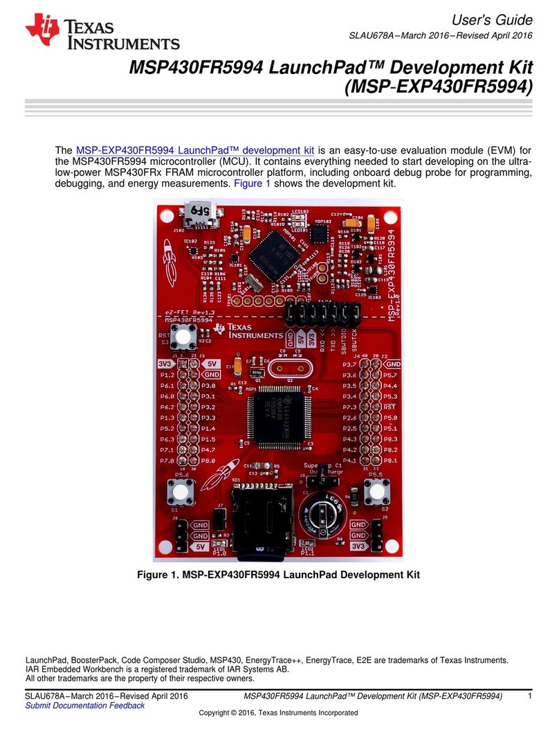
Texas Instruments LaunchPad MSP430FR5994 user guide
