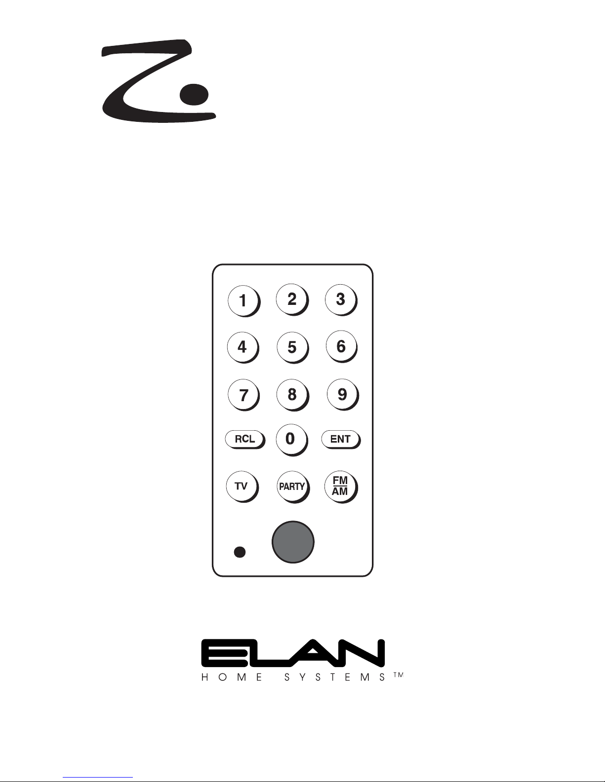
Introduction
The Z•150 Direct Access Keypad is a companion to the Z•100 Intelligent In-Wall
Keypad that expands functionality to include:
• Numerical source control
• Additional source select - TV
• Zone-specific tone, loudness, & enhancement controls
• DSS menu control
• IR receiver included
Note: Please see the Z•100 Installation Manual for important information about
the Z•100 Intelligent In-Wall Keypad.
IR Tube
The IR Tube is a high-gain Infrared Receiver that is mounted in the Z•150 Direct
Access Keypad. No additional wiring is required as the IR Tube simply plugs into a
connector located on the back of the Z•100 keypad. The drawing below shows the
IR Tube’s pinout should the plug be removed.
Installation
Rough-In Boxes
Z•100/Z•150 combinations will mount in most 32 cu. in. boxes.
Note: Please verify the internal interior dimension requirements
before specifying or installing J-boxes!
Use J-boxes with the following internal dimensions:
Z•100/Z•150 4”W X 3”H X 2.5”D
Keypads should be mounted at the same height as the light switches in the home. In
order to avoid Electro-Magnetic Interference (EMI), do not mount keypads close to
light dimmers. Leave at least one stud-bay open between keypads and dimmers
(leave more space if multiple dimmers are present). Do not mount keypads outdoors!
Corrosion will damage them. Also, when installing keypads with IR receivers, avoid
installing them in areas that will receive direct sunlight. The sunlight can flood the IR
receiver and make the system inoperative.
Wiring
Run Cat-5 wire from the head-end location to each Z•100/Z•150 location. Additional
Cat-5 is NOT NEEDED if using a Z•150 companion keypad. ELAN recommends the
use of C45P RJ-45 interface cables when installing keypads. The RJ-45 pinout for
each ELAN multi-room controller is included in the manual for that particular product.
Use of wire other than Cat-5 may produce undesired results (IR bandwidth can be nar-
rowed or interference may occur).
Note: Maximum keypad wire run is 500 feet.
Please consult your ELAN multi-room controller Installation Manual
for specific keypad connection details.
Stripe
Center
No Stripe
+12VDC
GND
IR
Connecting a Z•150 & IR Tube to a Z•100
Z•100
1. Make sure that the Z•100 is not connected to the ELAN multi-room controller,
Z•080, or stand-alone power supply.
2. Using the ribbon cable provided with the Z•150, push the multi-pin headers onto
the 12-pin jacks on both the Z•100 and the Z•150. Make sure that the stripe on
the ribbon cable lines up with Pin #1 on both ports.
Note: The Z•150 can be placed to either the right or left of the Z•100.
IR Tube
1. Make sure that the Z•100 is not connected to the ELAN multi-room controller,
Z•080, or stand-alone power supply.
2. Connect the IR Tube plug, TAB UP, to the 3-pin port located on the Z•100.
Programming
Allthough all Z•PADS come pre-programmed with ELAN default codes, it is necessary
to program them in order to achieve full functionality. IR commands must be down-
loaded to each keypad from VIA!®TOOLS setup software for each source that will be
controlled. Functionality will vary, depending on the needs of the homeowner.
Consult the table on p. 3 for specific ELAN system commands.
Note: Please see VIA!TOOLS Help file for detailed information about programming
Z•PADS.
Stripe
Stripe
Stripe
PIN 1
PIN 1
Ribbon Cable Position-No Z•025
PIN 1 PIN 1
100 150
Stripe
Ribbon Cable Position /w Z•025
Rear View
Programming
Allthough all Z•PADS come pre-programmed with ELAN default codes, it is necessary
to program them in order to achieve full functionality. IR commands must be down-
loaded to each keypad from VIA!®TOOLS setup software for each source that will be
controlled. Functionality will vary, depending on the needs of the homeowner.
Consult the table below for specific ELAN system commands.
Note: Please see VIA!TOOLS Help file for detailed information about
programming Z•PADS.
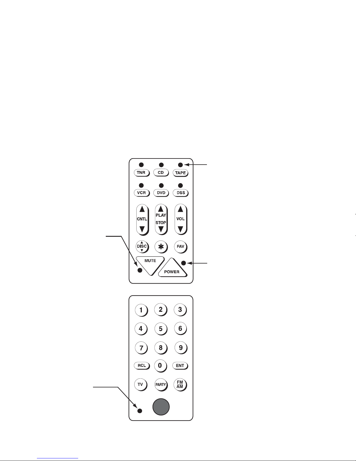
System Commands
The following table shows each system-level button and the ELAN default commands
that are associated with that button. Any button that is not listed in the table
is a normal button and can be programmed with a single IR code or a seven-step
sequence.
Note: Please see VIA!®TOOLS Help file for information about programming Z•PADS.
Z•100/150 BUTTON FUNCTION
Source 1-6 Selects Sources 1-6/Initiates Source-Select Sequence
OFF Press once for Zone OFF. Press twice for System OFF.
MUTE Zone MUTE ON/OFF toggle.
FAV Source-Specific Sequence, one per source
PARTY Global Sequence
*Used to access secondary function for each button
*Source 1-6 Selects sources 7-12/Initiates Source-Select Sequence
*VOLUME UP Whole-House Music ON
*VOLUME DN Whole-House Music OFF
*MUTE Do-Not-Disturb ON/OFF toggle
*FAV Global Sequence
*PARTY Global Sequence
*1 (Z•150 Only) Bass UP (Z, S12, and HD only)
*4 (Z•150 Only) Bass DOWN (Z, S12, and HD only)
*2 (Z•150 Only) Treble UP (Z, S12, and HD only)
*5 (Z•150 Only) Treble DOWN (Z and HD only)
*3 (Z•150 Only) Loudness Contour ON/OFF toggle (Z only)
*6 (Z•150 Only) Spatial Enhancement ON/OFF toggle (Z only)
*0 (Z•150 Only) EQ Flat (Z, S12, and HD only)
*7 (Z•150 Only) Global Sequence
*8 (Z•150 Only) Global Sequence
*9 (Z•150 Only) Global Sequence