Elan PVIA1 Valet User manual

PVIA1 Valet
Single Zone VIA!®Valet Wall Plate
Installation Manual


Important Information
NOTE: This equipment has been tested and found to comply
with the limits for a Class B digital device, pursuant to Part 15
of the FCC Rules. These limits are designed to provide reason-
able protection against harmful interference in a residential
installation. This equipment generates, uses and can radiate
radio frequency energy and, if not installed and used in ac-
cordance with the instructions, may cause harmful interference
to radio communications. However, there is no guarantee that
interference will not occur in a particular installation.
If this equipment does cause harmful interference to radio or
television reception, which can be determined by turning the
equipment off and on, the user is encouraged to try to correct
the interference by one or more of the following measures:
• Reorient or relocate the receiving antenna.
• Increase the separation between the equipment and receiver.
• Connect the equipment into an outlet on a circuit different
from that to which the receiver is connected.
• Consult the dealer or an experienced radio/TV technician for
help.
Caution: Changes or modifications not expressly approved by
ELAN could void the user’s authority to operate this equipment.

© 2008 ELAN Home Systems • All Rights Reserved Page 1
ELAN HOME SYSTEMS PVIA1 VALET
Table of Contents
Introduction .........................................................................3
Features ...........................................................................3
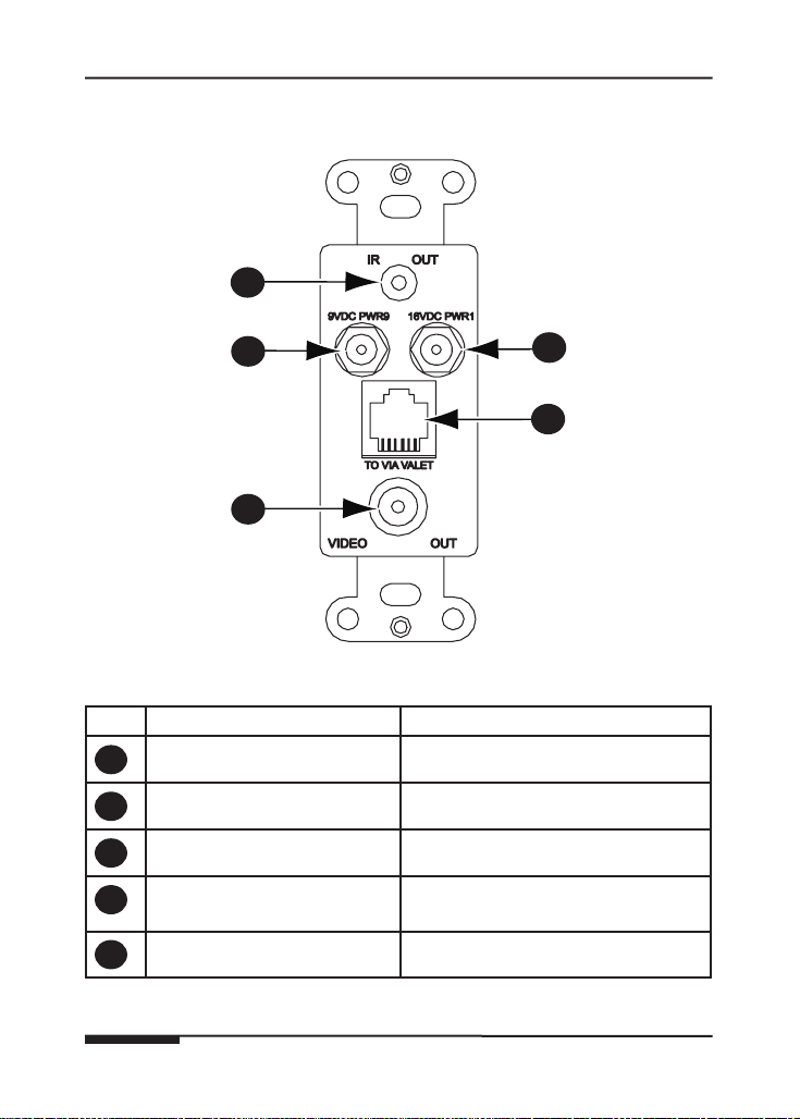
Front Panel Call-Out ........................................................4
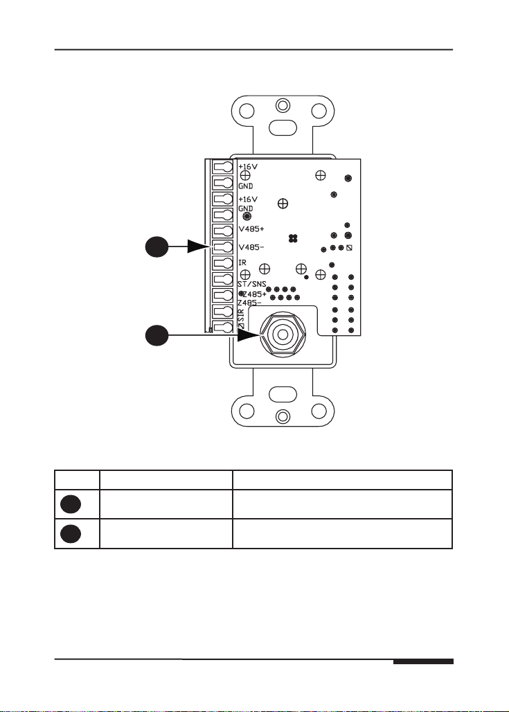
Rear Panel Call-Out ........................................................5
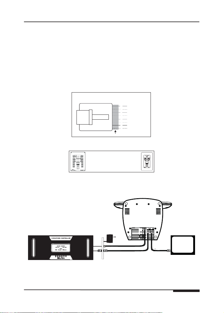
System Design .....................................................................6
Wire Runs ........................................................................7
Maximum Wire Length ....................................................8
Applications .....................................................................9
Stand-Alone .....................................................................9
Stand-Alone Expanded ...................................................10
Home Theater Serial Control ..........................................11
S12 Series ........................................................................12
SPP VIA! Power ...............................................................13
S8 Series ..........................................................................14
S6 Series ..........................................................................15
Connections .........................................................................16
Rear Panel Connections .................................................16
Standalone Connections ................................................17
S12 Series Connections ..................................................18
S8 Series Connections ....................................................19
S6 Series Connections ....................................................20
Chaining PVIA Wall Plates ..............................................21
PVIA1 Valet To SPP Application .....................................21
PVIA1 Valet To PVIA4 Application ..................................22
PVIA1 Valet To PVIA1 Inwall Application ........................23
Composite Video Connections .......................................25
IR Out Front .....................................................................26
IR Out To IR Block ...........................................................27
IR Out Rear ......................................................................28
Power Connection ...........................................................29
Power Sense ....................................................................30

PVIA1 VALET ELAN HOME SYSTEMS
Page 2 © 2008 ELAN Home Systems • All Rights Reserved
Troubleshooting ...................................................................31
Appendix A: Specifications ...............................................32
Appendix B: Added Features ............................................33
Warranty ...................................................................Back Page

ELAN HOME SYSTEMS PVIA1VALET
© 2008 ELAN Home Systems • All Rights Reserved Page 3
Introduction
The PVIA®1 Valet Precision Panel is designed to simplify the installation
of ELAN VIA!®Valet and provide a reliable, logical connectivity solution.
Designed to work with ALL Valet models (6.4 and 100EM), the PVIA1 has pro-
visions for each connection type required for a complete Valet installation.
The PVIA1 Valet version is included with each VIA!Valet.
•Use in stand-alone systems wherever a VIA!Valet is needed
•Use in ELAN S Series systems wherever a VIA!Valet is needed
•Use for local system control - perfect for Home Theaters!
Features
•Provides Power, IR & Video routing to a single VIA!Valet
•IR output port
•Status Sense input
•Video input (F connector-to-F connector video pass-through)
•Rear panel connector for S Series Precision Panel interface
•Single-gang Decora format
•PWR1 plug-in power supply included
A second version of the PVIA1 (the IN-WALL version) is used for non-Valet
VIA!®Touch Panel installations. The PVIA1 IN-WALL version is required for use
with the ELAN VIA! SC-4 and SS1 System Station RS-232 controllers. There
are also instances where the two PVIA1 versions are used together.
Figure 1-1: PVIA1 Valet

PVIA1 VALET ELAN HOME SYSTEMS
Page 4 © 2008 ELAN Home Systems • All Rights Reserved
PVIA1 VALET Front/Rear Panel
24
5
1
3
Figure 1-2: Front Panel Callout
Item Input/Output Description
1
IR Output 3.5mm Mono Mini jack
2
9 VDC Power Sense In 9 VDC PWR Cube Connection
3
Coaxial Video Out Coaxial Video Cable Connector
4
16 VDC Power Jack 16 VDC 1 Amp PWR1
Connection
5
RJ-45 Output System RJ-45 Cable Jack
Table 1-1: Front Panel Callout

ELAN HOME SYSTEMS PVIA1VALET
© 2008 ELAN Home Systems • All Rights Reserved Page 5
1
2
Figure 1-3: Rear Panel Callout
Item Input/Output Description
1
CAT-5 Terminal Strip Terminate CAT-5 conductors
2
Coaxial Video Input Coaxial Video Cable Connector
Table 1-2: Rear Panel Callout

PVIA1 VALET ELAN HOME SYSTEMS
Page 6 © 2008 ELAN Home Systems • All Rights Reserved
System Design
Proper system design ensures that all parts of a whole-house audio/video
system work together to provide the desired results. Each part of the system
(source A/V components, keypads, speakers, and the multi-room control-
ler, for example) must be carefully chosen and a location specified for each
device. Wiring needs must be carefully planned for. Building codes and
contruction methodology must be factored in to provide a safe and properly
functioning system. Before beginning any installation, it is advisable to con-
sult a set of building plans and a list of equipment and map out each part
of the system. Make sure to carefully locate speakers, keypads, touchpads,
touchpanels, and wire runs so as to avoid interference with other household
devices such as plumbing, doors, windows, and high-current electrical wires.
System Design is typically comprised of Prewire, Rough-In, and Trim-Out.
The following sections will describe each phase of the installation process
as they pertain to installing ELAN VIA!Valets and the PVIA1 Precision Panel
specifically.
TM
S8.6AV / S6 / S12
External Amplifier
COM2
A/V Sources
SPP
(side view)
Sensors
External IR
Receivers
SS1
Keypads
VIA!-SC4 or
AUDIO SENSOR
SPK SPK SPK SPK
Olé
Touchpads
FrontRear
Triggered
Devices
PVIA1 Valet
Figure 2-1: System Design

ELAN HOME SYSTEMS PVIA1VALET
© 2008 ELAN Home Systems • All Rights Reserved Page 7
WIRE RUNS
Runs of Cat-5 for IR and Data transmission and RG-6 or RG-59 for Video
signals are required between the Valet PVIA1 and the central equipment loca-
tion. If the VIA!Valet is powered locally only a single run of Cat- 5 and a single
run of coax will be necessary.
If the VIA!Valet is to be powered by a power supply located at the “head-
end” location of a multi-room system, refer to the table on the following page
for minimum wiring requirements.
BLUE
WHITE/BLUE
ORANGE
WHITE/ORANGE
GREEN
WHITE/GREEN
BROWN
WHITE/BROWN
1
2
3
4
5
6
7
8
PIN # COLOR CODE
FRONT
CABLE
Standard ELAN RJ-45 Pin-Out
TA B
ELAN Precision Panels save
time and make sense out
of complex wiring jobs!
+
--
VIA!NET
16VDC/10A
16VDC/4A
16VDC/1.5A
1
ZONE
2
ZONE
3
ZONE
4
ZONE
SS/SC4
5
ZONE
6
ZONE
7
ZONE
8
ZONE
TOSENSEINPUTSEXTIR
123
USESTEREO3.5mm PLUGS ONLY
456
1
TRIGGERS
234
5678
POWER
Figure 2-2: ELAN RJ-45 Pin-Out
TV
ELAN S12
Cat-5
RG-59
PVIA1
Valet
PWR1
VIA!Valet100
Figure 2-3: Wiring Overview

PVIA1 VALET ELAN HOME SYSTEMS
Page 8 © 2008 ELAN Home Systems • All Rights Reserved
These are the maximum wire run lengths when using the following cables to
provide power to the VIA!Valet Touch Panel when the power supply is located
in the “head-end”:
24 AWG
Cat-5
18 AWG
Stranded
16 AWG
Stranded
14 AWG
Stranded
110 ft. 225 ft. 575 ft.360 ft.
Table 2-1: Maximum Wire Lengths

ELAN HOME SYSTEMS PVIA1VALET
© 2008 ELAN Home Systems • All Rights Reserved Page 9
Applications
Local System or Home Theater Control Using
VIA!Valet
The VIA!Valet comes with a pre-terminated interface cable assembly that
combines Cat-5 and RG-59 coaxial cable for the Transmission of Power, IR
and Video signals between the PVIA1 Valet and the VIA!Valet Touch Panel.
The VIA!Valet can be used for any stand-alone (non-ELAN) system applica-
tion or as a Home Theater controller. The Figure 2-4 below shows a basic
application using one VIA!Valet100EM, a PVIA1 Valet Wall Plate and an ELAN
IR Emitter to control an A/V Receiver.
A/V Receiver
PVIA1 Valet
To Front
of PVIA1
Valet
ELAN
IR Emitter
Figure 2-4: Stand-Alone Application
NOTE: When IR is connected to the front of the PVIA1 Valet, IR pass-
through on the rear is disabled

PVIA1 VALET ELAN HOME SYSTEMS
Page 10 © 2008 ELAN Home Systems • All Rights Reserved
Stand-Alone System- Expanded
Stand-alone systems (without an ELAN multi-room controller) can be as
simple as one VIA!Valet100EM controlling one IR source, or as complex as a
VIA!Valet100EM, System SS1, ELAN Sensors all controlling many IR sources
and Serial devices as shown in Figure 2-6. Figure 2-5 below shows a
VIA!Valet100EM, A PVIA1 Valet Wall Plate, two VIA!70EMs and a PVIA4 Wall
Plate controlling a stack of A/V gear. See VIA!Tools for additional program-
ming details.
PVIA4
PVIA-4
VIDEO
IN
1234
+16VDC
POWER
9VDC
SENSE
INPUTS
IR
OUT
12
34
ALL
SYS
SENSE
TO VIA!NET
12
34
16 VDC/
4A
PWR4
PVIA1 Valet
PWR1
IR OUT
VIDEO OUT
9VDCPWR9 16VDCPWR1
TO VIAVALET
Digital Music Server
Satellite
DVD
IR Emitter
IR Emitter
IR Emitter
Amplified IR
Connection Block
PWR2
Required only if
connectingmore
than 4 VIA!s tothe
PVIA4 Wall Plate
VIA!70EM X 2
Figure 2-5: Stand-Alone Expanded Application

ELAN HOME SYSTEMS PVIA1VALET
© 2008 ELAN Home Systems • All Rights Reserved Page 11
Stand-Alone System w/ RS-232 Subsystems
This application adds the control capabilities of an SS1 System Station to
control a projection screen and drapes using relays and a 1 and 2-way RS-
232 control devices. Consult the SS1 System Station manual for details.
AUDIO SENSOR
CONTACT SENSOR
LED/LIGHT SENSOR
Relay
Screen Drapes
IR Emitter
IR Emitter
IR Emitter
SYSTEM SS1
ELAN SENSE
Sensors
®
Relay Controlled Devices (x8)
Home Theater
Components
IR Outputs (x12)
Sense Inputs (x6)
1 & 2-Way
RS-232 Controlled
Devices (x4) RS-232
PVIA-1
Valet
TOVIA!VALET
IR OUT
VIDEO IN
9VDCPWR9 16VDCPWR1
Local Port
HOST RS-232
ELAN RS-232
HOST
ELAN
COM 1
COM 3
COM 2
COM 4
COM1
COM2
COM3
COM4
ETHERNET
LINK
RX/TX
IR-LINK
SENSE INPUTS
123
456
ALL IR OUTPUT
EXT IR INPUT
IR OUTPUTS
1
7
2
8
3
9
4
10
5
11
6
12
VIA-NET
IR
PWR
SS1
POWER
12VDC
0.5 AMPS
-+
LEXINGTON,KY • MADE IN CHINA
MODEL:SS1 SYSTEM STATION
WARNING: DO NOT REMOVE COVER.
NO USER SERVICEABLE PARTSINSIDE.
REFER SERVICE TO ELAN-APPROVED
SERVICETECHNICIAN.
PWR
GND
NC
COM
NO
PWR
GND
NC
COM
NO
PWR
GND
NC
COM
NO
PWR
GND
NC
COM
NO
PWR
GND
NC
COM
NO
PWR
GND
NC
COM
NO
PWR
GND
NC
COM
NO
PWR
GND
NC
COM
NO
PWR
GND
RELAY 1 RELAY 2 RELAY 3 RELAY 4 RELAY 5 RELAY 6 RELAY 7 RELAY8
DC RELAY PWR
DOWN-
LOAD
ENABLE
®
PWR1
Figure 2-6: Stand-Alone System w/ SS1 System Station

PVIA1 VALET ELAN HOME SYSTEMS
Page 12 © 2008 ELAN Home Systems • All Rights Reserved
System12 (S12)
ELAN’s SPP Precision Panel for the System12 Multi-Room A/V Controller
(S12) makes quick work out of configuring a VIA!Valet Touch Panel to con-
trol S12 zones. Unlike in-wall VIA!s, a PVIA1 Valet Wall Plate is necessary
when using a VIA!Valet with an S12. The Figure 2-7 below shows one
VIA!Valet100EM Touch Panel, one PVIA1 Valet Wall Plate, four VIA!70EM
Touch Panels, and a SPP connected to an ELAN S12.
S12
PVIA1 Valet
SPP
IR OUT
VIDEO OUT
9VDCPWR9 16VDCPWR1
TO VIAVALET
+
--
VIA!NET
16VDC / 10A
16VDC / 4A
16VDC/1.5A
1
ZONE
2
ZONE
3
ZONE
4
ZONE
SS/SC4
5
ZONE
6
ZONE
7
ZONE
8
ZONE
TO SENSE INPUTSEXTIR
123
USE STEREO 3.5mm PLUGS ONLY
456
1
TRIGGERS
234
5678
POWER
16VDC
10.0A
PWR10
VIA!70EM X 4
Figure 2-7: S12 Application
NOTE: A PS12 Precision Panel may be used with System12
applications.

ELAN HOME SYSTEMS PVIA1VALET
© 2008 ELAN Home Systems • All Rights Reserved Page 13
16 VDC/
4A
16V/4A Power Supply Connections 16V
/
10A Power
S
upply
C
onnections
ELAN PWR4
16V/4A
Power Supply
+
--
16VDC / 10A
16VDC / 4A
16VDC/1.5A
POWER
+
--
16VDC / 10A
16VDC / 4A
16VDC/1.5A
POWER
+
--
16VDC / 10A
16VDC / 4A
16VDC/1.5A
POWER
16V/1.5A Power Supply Connections
PWR1
POWER
SUPPLY
ELAN PWR1
16V/1.5A
Power Supply
16VDC
10.0A
Olé = 150mA
VIA! = 1A
PWR4 = 4A
PWR10 = 10A
IMPORTANT NOTE
Olé Touchpads
and VIA! Touch Panels
Use the correct power
supply connected to the front
of the SPP for the number
of Olé Touchpads and VIA!
Touch Panels in the system.
PWR1 = 1.5A
Figure 2-8: VIA! Power for SPP

PVIA1 VALET ELAN HOME SYSTEMS
Page 14 © 2008 ELAN Home Systems • All Rights Reserved
System8 (S8)
The VIA!Valet100EM’s flexibility makes it a good candidate for System8 (S8.6)
applications. Use a PVIA1 Valet Wall Plate for each VIA!Valet100EM to be
installed. The Figure 2-10 below shows a VIA!Valet100EM, a PVIA1 Valet
Wall Plate, four VIA!70EMs and a SPP Precision Panel configured for use with
an ELAN S8.6.
PVIA1
Valet
S8.6
PWR4
PWR1
IR OUT
VIDEO OUT
9VDCPWR9 16VDCPWR1
TO VIAVALET
+
--
VIA!NET
16VDC / 10A
16VDC / 4A
16VDC/1.5A
1
ZONE
2
ZONE
3
ZONE
4
ZONE
SS/SC4
5
ZONE
6
ZONE
7
ZONE
8
ZONE
TO SENSE INPUTSEXTIR
123
USE STEREO 3.5mm PLUGS ONLY
456
1
TRIGGERS
234
5678
POWER
SPP
16 VDC/
4A
R
VIA!70EM X 4
Figure 2-9: S8 Application

ELAN HOME SYSTEMS PVIA1VALET
© 2008 ELAN Home Systems • All Rights Reserved Page 15
System6 (S6)
The VIA!Valet100EM is ideal for System6 (S6) applications. Use a PVIA1 Valet
Wall Plate for each VIA!Valet100EM to be installed. The Figure 2-9 below
shows a VIA!Valet100EM, a PVIA1 Valet Wall Plate, three VIA!70EMs and a
SPP Precision Panel configured for use with an ELAN S6.
PVIA1
Valet
S6
PWR4
PWR1
IR OUT
VIDEO OUT
9VDCPWR9 16VDCPWR1
TO VIAVALET
+
--
VIA!NET
16VDC / 10A
16VDC / 4A
16VDC/1.5A
1
ZONE
2
ZONE
3
ZONE
4
ZONE
SS/SC4
5
ZONE
6
ZONE
7
ZONE
8
ZONE
TO SENSE INPUTSEXTIR
123
USE STEREO 3.5mm PLUGS ONLY
456
1
TRIGGERS
234
5678
POWER
SPP
16 VDC/
4A
R
VIA!70EM X 3
Figure 2-10: S6 Application

PVIA1 VALET ELAN HOME SYSTEMS
Page 16 © 2008 ELAN Home Systems • All Rights Reserved
Connections
Rear Panel
ELAN recommends using Cat-5 cable for connections to the SPP from the
PVIA1 Valet. Refer to the SPP Overlay being used for the correct pin-out.
SPP to PVIA1VALET (Using 16 VDC from SPP)
Cat-5
PVIA-1
GND
+16V
GND
SIR
Z485-
Z485+
ST/SNS
IR
V485-
V485+
+16V
White/Blue
Orange
White/Orange
Green
White/Green
Brown
White/Brown
nc
nc
nc
Cat-5
PVIA-1
GND
+16V
GND
SIR
Z485-
Z485+
ST/SNS
IR
V485-
V485+
+16V
White/Blue
Orange
White/Orange
Green
White/Green
Brown
White/Brown
nc
nc
nc
Blue
Blue
N/C
IR
485-
485+
G
16V
G
16V
Blue
White/Blue
Orange
White/Orange
Green
White/Green
Brown
White/Brown
N/C
IR
485-
485+
G
16V
G
16V
Blue
White/Blue
Orange
White/Orange
Green
White/Green
Brown
White/Brown
SPP to PVIA1VALET (Using 16 VDC from PVIA1)
X
X
X
X
X
X
SPP
SPP
Figure 3-1: PVIA1 Wiring
When connecting a PVIA1 Valet
Wall Plate to the SPP, use either the
included PVIA1 power supply connected
to the PVIA1 Wall Plate, or a PWR10,
PWR4 or PWR1 power supply connected
to the SPP.
DO NOT USE BOTH POWER SUPPLIES!

ELAN HOME SYSTEMS PVIA1VALET
© 2008 ELAN Home Systems • All Rights Reserved Page 17
Stand-Alone/Home Theater
The VIA!Valet is ideal for use as a stand-alone system controller or Home
Theater controller. For control of a Home Theater system, the VIA!Valet100EM
and PVIA1 Valet Wall Plate are combined with a method for IR distribution
such as ELAN’s IRD4 Amplified Connection Block. Signals originate at the
VIA!Valet100EM, pass through the PVIA1 Valet Wall Plate, then travel to the
connection block where they are routed to each component.
NOTE: This application does not allow for independent control of identical
sources. An ELAN multi-room controller or SS1 System Controller should
be used in that scenario.
Amplified IR
Connection Block
+16V
GND
+16V
GND
V485+
V485-
IR
ST/SNS
Z485+
Z485-
SIR
Sources
PVIA1 Valet
Rear
To Front
of PVIA1
Valet
PWR2
ELAN
IR Emitters
PWR1
Figure 3-2: Stand-Alone Connections
Table of contents
Other Elan Home Automation manuals