ELAP CANopen MEM40B User manual

HARDWARE CONFIGURATION
SETTING THE NODE ID
MEM40 CANOPEN ENCODER PROFILE
Complying with standards CiA DS 301
“Application Layer and Communication Profile” and
DS 406 “Device Profile for Encoders”
Class C2
MECHANICAL & ENVIRONMENTAL SPECIFICATIONS
MEM-Bus
40B41B
Materials: case
shaft
Aluminium
Stainless steel
Weight
100 g ca
Shaft/hollow shaft Ø
6, 8 ,10 mm
8, 10 mm
Revolutions/minute
6000
Starting torque
0,2 Ncm
Intertia
5 g cm2
Max load
Magnetic
Vibrations resistance
(10÷2000 Hz)
8192 steps/rev –13 bit
Shock (11 ms)
65536/16 bit
Protection degree
< 1 s
IP65
Operating
temperature
>21 years power off
Stocking temperature
-20 ÷ 80°C
ELECTRICAL & OPERATING SPECIFICATIONS
Operating principle
Magnetic
Resolution/revoltution
8192 steps/rev –13 bit
Revolutions no.
(multiturn)
65536/16 bit
Initializing time
< 1 s
Data memory
>30 years power off
Fieldbus
CANopen
Supply
10 ÷ 30 Vdc
Protection against polarity reversal
Power consumption
2 W
Accuracy
± 0.2°
Connection
M12 5 5 pin radial connector
Interference immunity
EN 61000-6-2
Emitted interference
EN61000-6-4
Encoder assoluti mono o multigiro
Bus di campo: Profibus DP
Risoluzione elevata
Diverse configurazioni disponibili
MEM40B-MEM41B
CANopen
Quick Reference Guide
The node ID (user address) is defined/modified in object 2101H or via LSS.
In addition it is possible to set the user address using
two rotary switches of the encoder (see TABLE 5.1). The max. set is 99.
If the switches are set at 0, at power on the encoder keeps as node number
the one stored in object 2101H; otherwise it keeps the one set with the
rotating switches.
The default set of the two switches is 00.
The encoder rear cap must be removed to gain access to two rotary switches, one 4-pin DIP switch and one 8-pin tap connector
(Picture 5.1).
).
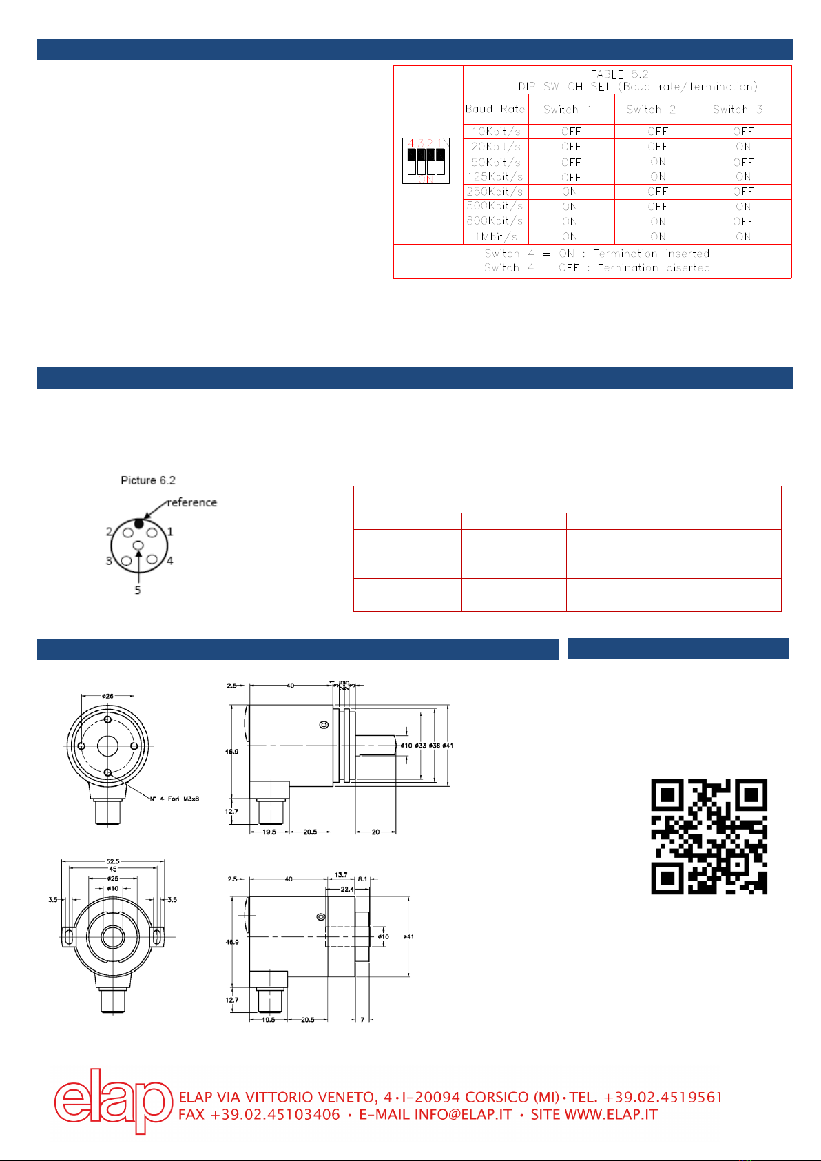
BAUD RATE SETTING
CONNECTIONS
The bus and supply cables must be connected to the M12 connector as shown in the Picture 6.2 and in the TABLE 6.2.
The encoder should always be connected with shielded conductors. The cable shield should be in placed at both ends of the cable.
Connectors must be selected to permit a 360 degree contact of the shield . Ensure that no equalizing currents are discharged via the
shield. As the encoder is not always connected to a defined earth potential depending on its mounting position, the encoder flange
should always be additionally linked to earth potential.
DIMENSIONS
Ref. M2081
Ref M2116
REFERENCES
Catalogues, Manuals, Software
available at :
https://www.elap.it/absolute-
encoders/encoder-mem40-canopen/
The baud rate is defined/modified in object 2100H or via
LSS. In addition it is possible to set the
baud rate by means of contacts 1, 2 and 3 of the encoder
DIP switch (see TABLE 5.2).
If the switches relating to the baud rate are set at 0, at power
on the encoder keeps as baud rate the one stored in object
2100H; otherwise it keeps the one set with the DIP switch.
The default set of the DIP swicht contacts 1, 2 and 3 is: OFF
ON OFF.
Terminating resistor
If the connected encoder is the last device in the bus line, the
bus must be terminated with a resistor. The resistor can be
connected by the contact 4 of the encoder DIP switch (see
TABLE 5.2).
The default set of the DIP swicht contact4 is: OFF.
M12 male connector –insertion side
TABLE 6.1
5 PIN CONNECTOR –PIN ASSIGNEMENT
PIN NO.
NAME
DESCRIPTION
1
SHIELD
SHIELD CONNECTION
2
+V
10-30 VDC SUPPLY POSITIVE POLE
3
0V
10-30 VDC SUPPLY 0 V
4
CAN-H
CAN BUS HIGH SIGNAL
5
CAN-L
CAN BUS LOW SIGNAL
The resistor can be inserted by means of the DIP switch contact 4.
The defalult set of DIP switch pin 4 is OFF.
MEM40B
MEM41B
This manual suits for next models
1
Other ELAP Media Converter manuals


