ELAP MEM-BUS 620 User manual

CONNECTIONS
MEM-BUS CANopen ENCODER PROFILE
Complying with standards CiA DS 301 “Application Layer
and Communication Profile” and DS 406 “Device Profile for
Encoders”
Class C2
MECHANICAL & ENVIRONMENTAL SPECIFICATIONS
MEM-Bus
620/520/540
410/430
Materials: case
shaft
Aluminium
Stainless steel
Weight
500 g ca.
Shaft/joint hole Ø
6, 8 ,10 mm
8, 10, 12, 14, 15 mm
Revolutions/minute
6000
Starting torque
0.8 Ncm
Intertia
25 g cm2
Max load
80 N axial/100 N radial
Vibrations resistance
(10÷2000 Hz)
100 m/sec2
Shock (11 ms)
50 G
Protection degree
IP65 optional IP67
IP65
Operating
temperature
-30 ÷ 70°C
Stocking
temperature
-30 ÷ 85°C
ELECTRICAL & OPERATING SPECIFICATIONS
Operating principle
Magnetic
Resolution/revoltution
8192 steps/rev –13 bit
Revolutions no. (multiturn)
65536/16 bit
Initializing time
< 1 s
Data memory
>21 years power off
Fieldbus
CANopen
Supply
5 ÷ 28 Vdc
Protection against polarity reversal
Power consumption
2 W
Accuracy
± ½ LSB
Connection
3 cableglands or 2 cableglands or 2
M12 connectors
Interference immunity
EN 61000-6-2
Emitted interference
EN61000-6-4
Encoder assoluti mono o multigiro
Bus di campo: Profibus DP
Risoluzione elevata
Diverse configurazioni disponibili
MEM-BUS CANopen
Quick Reference Guide
The encoder rear cover must be removed by unscrewing the fastening
screws, to gain access to two rotary switches, one 4-pin DIP switch and
one 8-pin tap connector (Picture 5.1).
The 8-pin tap connector can be disconnected and is supplied inserted in
the corresponding plug connector.
Picture 5.1
SETTING THE USER ADDRESS (NODE ID)
As mentioned previously, the node ID (user address) is
defined/modified in object 2101H . In addition, it is
possible to set the user address using two rotary
switches of the encoder (see TABLE 5.1). The max. set is
99.
If the switches are set at 0, at power on the encoder
keeps as node number the one stored in object 2101H;
otherwise it keeps the one set with the rotating switches.
The default set of the two switches is 01.
Table 10.1
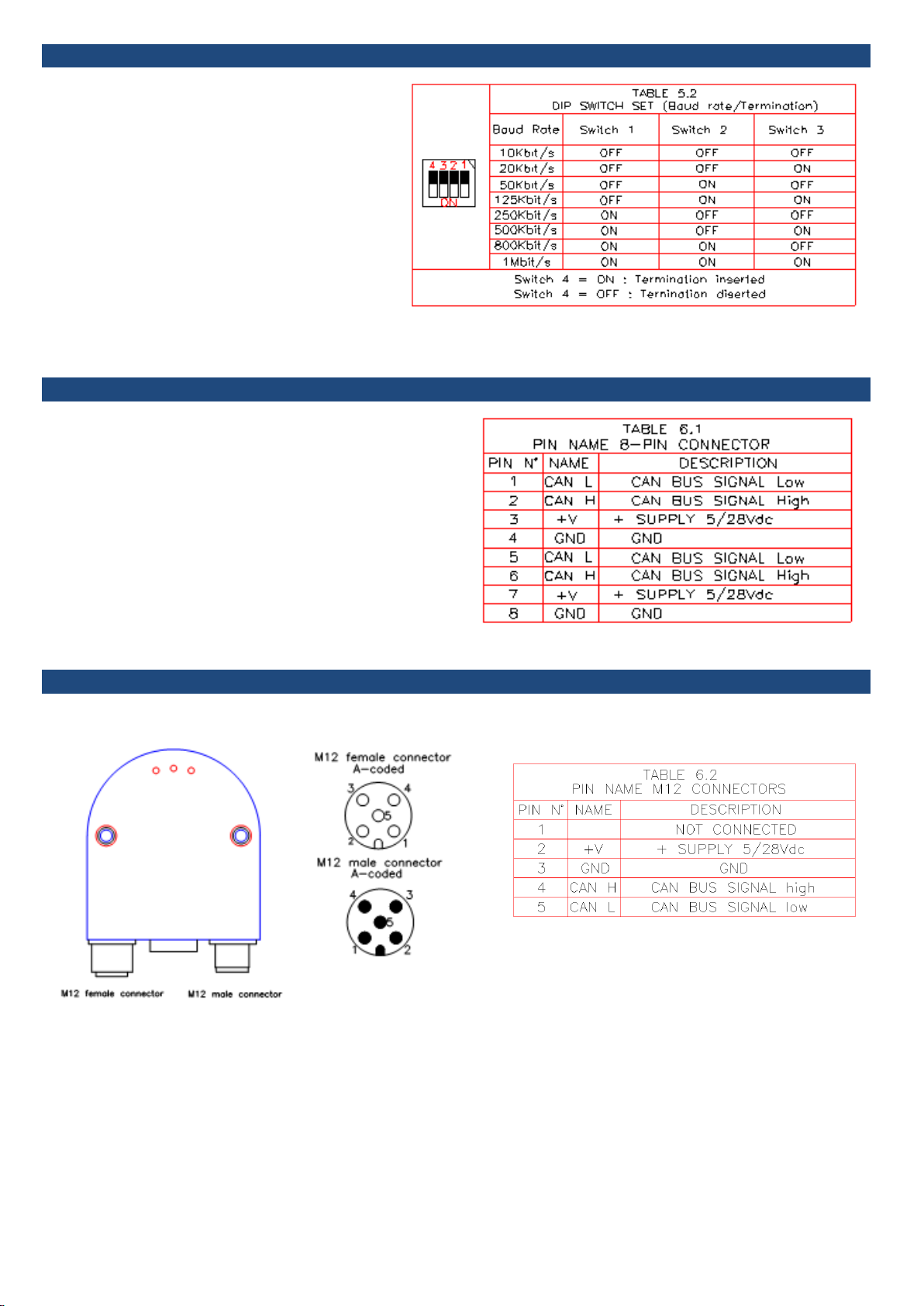
SETTING THE BAUD RATE
CONNECTIONS WITH CABLE GLAND PG9
CONNECTIONS WITH M12 CONNECTORS
The bus and supply cables must be connected to the M12 connector as shown in the Picture 6.2 and in the TABLE 6.2.
s and supply cables must be connected to the M12 connector as shown in the Picture 6.2 and in the TABLE 6.2.
As mentioned previously, the baud rate is
defined/modified in object 2100H . In addition, it is
possible to set the baud rate by means of contacts 1,
2 and 3 of the encoder DIP switch (see TABLE 5.2).
If the switches relating to the baud rate are set at 0, at
power on the encoder keeps as baud rate the one
stored in object 2100H; otherwise it keeps the one set
with the DIP switch.
The default set of the DIP swicht contacts 1, 2 and 3
is: OFF ON OFF.
Terminating resistor
If the connected encoder is the last device in the bus
line, the bus must be terminated with a resistor. The
resistor can be connected by the contact 4 of the
encoder DIP switch (see TABLE 5.2).
The default set of the DIP swicht contact4 is: OFF.
The bus and supply cables must be connected to the 8-pin tap
connector as shown in the Picture 5.1 and in the TABLE 6.1.
The pins mentioned with the same indication in the table 6.1 are
common inside the encoder.
The following procedure is recommended to connect the cables
to the encoder:
•Unfasten and remove the encoder rear cover
•Arrange the cables as shown in the Picture 6.1 and fasten them
in the relevant nuts in the cover
•Unplug and wire the 8-pin tap connector
Picture 6.2
The male connector pins and the female connector pins with same number are common inside the encoder (except pins 1)
Across the pins +V and GND of one connector and the corresponding pins of the other connector the current must not exceed 2 A.

SHIELDING
DIMENSIONS
CONNECTIONS BY P9 CABLE GLANDS
Ref M1395V
MEM430Bus
Ref M1419V
*AVAILABLE SHAFT DIAMETER
8 –10 length 20 mm
6 mm lengtrh 10 mm
*AVAILABLE SHAFT DIAMETER
8 –10 length 20 mm
6 mm lengtrh 10 mm
*AVAILABLE SHAFT DIAMETER
8 –10 length 20 mm
6 mm lengtrh 10 mm
*AVAILABLE HOLE DIAMETER
8 –10 –12 –14 –15 mm
*AVAILABLE HOLE DIAMETER
8 –10 –12 –14 –15 mm
Picture10.1
As the encoder is not always connected to a defined earth potential
depending on its mounting position, the encoder flange should
always be additionally connected to earth potential.
The encoder should always be connected to a shielded conductor.
If possible the cable shield should be placed at both ends. Ensure
that no equalizing currents are discharged via the encoder.
The Picture 10.1 shows the correct way a cable should be
connected to the encoder.
Bend the shield and place it all around the plastic cylinder
containing the cable gland sealing gasket.
Insert the cylinder in the relevant cap nut and screw the metal cap.
Connectors must be selected to permit a 360 degree contact of the
shield.

This manual suits for next models
4
Other ELAP Media Converter manuals


Popular Media Converter manuals by other brands

Turbines
Turbines PT420 manual

Trelawny
Trelawny LR2 Operation and maintenance manual

Harman Kardon
Harman Kardon SC6 owner's manual

North Star
North Star Essentio operating manual

METRObility Optical Systems
METRObility Optical Systems twister 2131-34-01 Installation & user guide

GSS
GSS PHDQ 1000 ASI DF Assembly instructions


