ELAP MEM40 Bus User manual

.docx
MULTI-TURN ABSOLUTE
ENCODERS
MEM40 Bus
MEM41 Bus
With CANopen Fieldbus
Instruction Manual
CERTIFICATE NO. E510647

Encoder MEM40B –MEM41B with CANopen protocol –Instruction Manual
I
MEM40B_CAN_Inglese_ul.docx 16/11/2020
CONTENTS
1. CAN bus & CANopen protocol......................1
1.1 CAN bus..........................................................1
1.2 CAN bus Characteristics ..............................1
1.3 CANopen ........................................................ 1
1.4 Communication Profile .................................2
1.5 CANopen Message Structure...................... 2
1.6 Service Data Communication.......................3
1.7 Process data communication....................... 5
1.8 Emergency service........................................5
1.9 Network Management (NMT)........................ 6
1.10 Layer Setting Services (LSS)...................... 8
2. Encoder communication profile..................12
2.1 Overview of encoder objects...................... 12
2.2 Parameters saving.......................................15
3. Diagnosis and useful information...............15
3.1 Error diagnosis field bus communication.15
3.2 Error diagnosis via field bus ......................16
3.3 Further useful information..........................16
3.4 Signaling LEDs ............................................16
4. Applications ..................................................17
4.1 Reading and setting objects.......................17
4.2 Configuration ...............................................18
4.3 Operation......................................................20
5. Hardware configuration ................................21
6. Connections...................................................22
7. Technical Specifications...............................23
SAFETY
The encoder must be installed by qualified experts only, with net voltage off and standstill shaft. Always
observe the operating instructions of the machine manufacturer. It is recommended to keep the present
manual for reference.
Always observe prevention and safety norms during the installation and operation of the device.
Use the encoder exclusively for its intended purpose.
High voltage, current and rotating parts may cause serious or fatal injuries.
Encoders must not be operated outside the specified limited values (see detailed product
documentation).
TRANSPORT AND STORAGE
Always transport or store encoders in their original packaging.
Never drop encoders or expose them to major vibrations.
MECHANICAL ASSEMBLY
Do not open the device.
Do not carry out mechanical changes on the device.
Avoid impacts or shocks on the housing and shaft.
Operate the device within its environmental specifications. Max ambient temperature 80°C.
ELECTRICAL SUPPLY
Carry out the wiring operations exclusively with unplugged voltage supply
Do not operate on the electrical plant while the encoder is on.
Ensure that the entire plant complies with EMC requirements.
CERTIFICATE NO. E510647

Encoder MEM40B –MEM41B with CANopen protocol –Instruction Manual
1
MEM40B_CAN_Inglese_ul.docx
Absolute Encoder with CANopen protocol, Class C2
1. CAN bus & CANopen protocol
1.1 CAN bus
The CAN bus (CAN: Controller Area Network) was originally developed by Bosch and Intel as a means of
fast, low-cost data transmission in automotive applications. The CAN bus is used today also in industrial
automation applications.
The CAN bus is a field bus (the standards are defined by CiA, the CAN in Automation Association)
through which devices, actuators and sensors from different manufacturers can communicate with each
other.
Elap encoder complies with standards CiA DS 301 “Application Layer and Communication Profile” and DS
406 “Device Profile for Encoders.”
1.2 CAN bus Characteristics
Data rate of 1 MBaud with network expansion up to 40
Network connected on both sides
The bus medium is a twisted-pair cable
„Real-Time‟ operation: a max wait time is set for high priority messages
Theoretically 127 users at one bus, but physically only 32 are possible (due to the driver).
Ensures data consistency across the network. Damaged messages are notified as faulty for all
network nodes
Message-oriented communication: the message is identified by a message identifier. All network
nodes use the identifier to test whether the message is of relevance for them.
Broadcasting, multicasting: All network nodes receive each message simultaneously. Synchronization
is therefore possible.
Multimaster capability: Each user in the field bus is able to independently transmit and receive data
without being dependent upon the priority of the master. Each user is able to start its message when
the bus is not occupied. When messages are sent simultaneously, the user with the highest priority
prevails.
Prioritization of messages: The identifier defines the priority of the message. This ensures that
important messages are transmitted quickly via the bus
Residual error probability: Safety procedures in the network reduce the probability of an undiscovered
faulty data transmission to below 10 -11. In practical terms, it is possible to ensure a 100% reliable
transmission.
Function monitoring: Localization of faulty or failed stations. The CAN protocol encompasses a
network node monitoring function. The function of network nodes which are faulty is restricted, or they
are completely uncoupled from the network.
Data transmission with short error recovery time: By using several error detection mechanisms,
falsified messages are detected to a high degree of probability. If an error is detected, the message
transmission is automatically repeated.
In the CAN Bus, several network users are connected by means of a bus cable. Each network user is
able to transmit and receive messages. The data between network users is serially transmitted.
Examples of network users for CAN bus devices are:
Automation devices such as PLCs
PCs
Input and output modules
Drive control systems
Analysis devices, such as a CAN monitor
Control and input devices as Human Machine Interfaces (HMI)
Sensors and actuators
1.3 CANopen
Under the technical management of the Steinbeis Transfer Centre for Automation, the CANopen profile
was developed on the basis of the Layer 7 specification CAL (CAN Application Layer). In comparison with
CAL, CANopen only contains the functions suitable for this application. CANopen thus represents only a
partial function of CAL optimized for the application in hand, so permitting a simplified system structure
and the use of simplified devices. CANopen is optimized for fast data exchange in real time systems.
The organization CAN in Automation (CiA) is responsible for the applicable standards of the relevant
profiles.

Encoder MEM40B –MEM41B with CANopen protocol –Instruction Manual
2
MEM40B_CAN_Inglese_ul.docx
CANopen permits:
• Simplified access to all device and communication parameters
• Synchronization of several devices
• Automatic configuration of the network
• Cyclical and event-controlled process data communication
CANopen comprises four communication objects (COB) with different characteristics:
• Process data objects for real time data (PDO)
• Service data objects for parameter and program transmission (SDO)
• Network management (NMT, Heartbeat)
• Pre-defined objects (for synchronization, emergency message)
All device and communication parameters are subdivided into an object directory. An object directory
encompasses the name of the object, data type, number of subindexes, structure of the parameters and
the address. According to CiA, this object directory is subdivided into three different parts. Communication
profile, device profile and a manufacturer-specific profile.
1.4 Communication Profile
Communication between the network users and the Master (PC / Control) takes place by means of object
directories and objects. The objects are addressed via a 16 bit index. The CANopen communication
profile DS 301 standardizes the various communication objects.
They are accordingly divided into several groups:
• Process data objects PDO for real time transmission of process data
• Service data objects SDO for read/write access to the object directory
• Objects for synchronization and error display of CAN users:
SYNC object (synchronization object) for synchronization of network users
EMCY object (emergency object) for error display of a device or its peripherals
• Network management NMT for initialization and network control
• Layer Setting Services LSS for configuration by means of serial numbers, revision numbers etc. in the
middle of an existing network
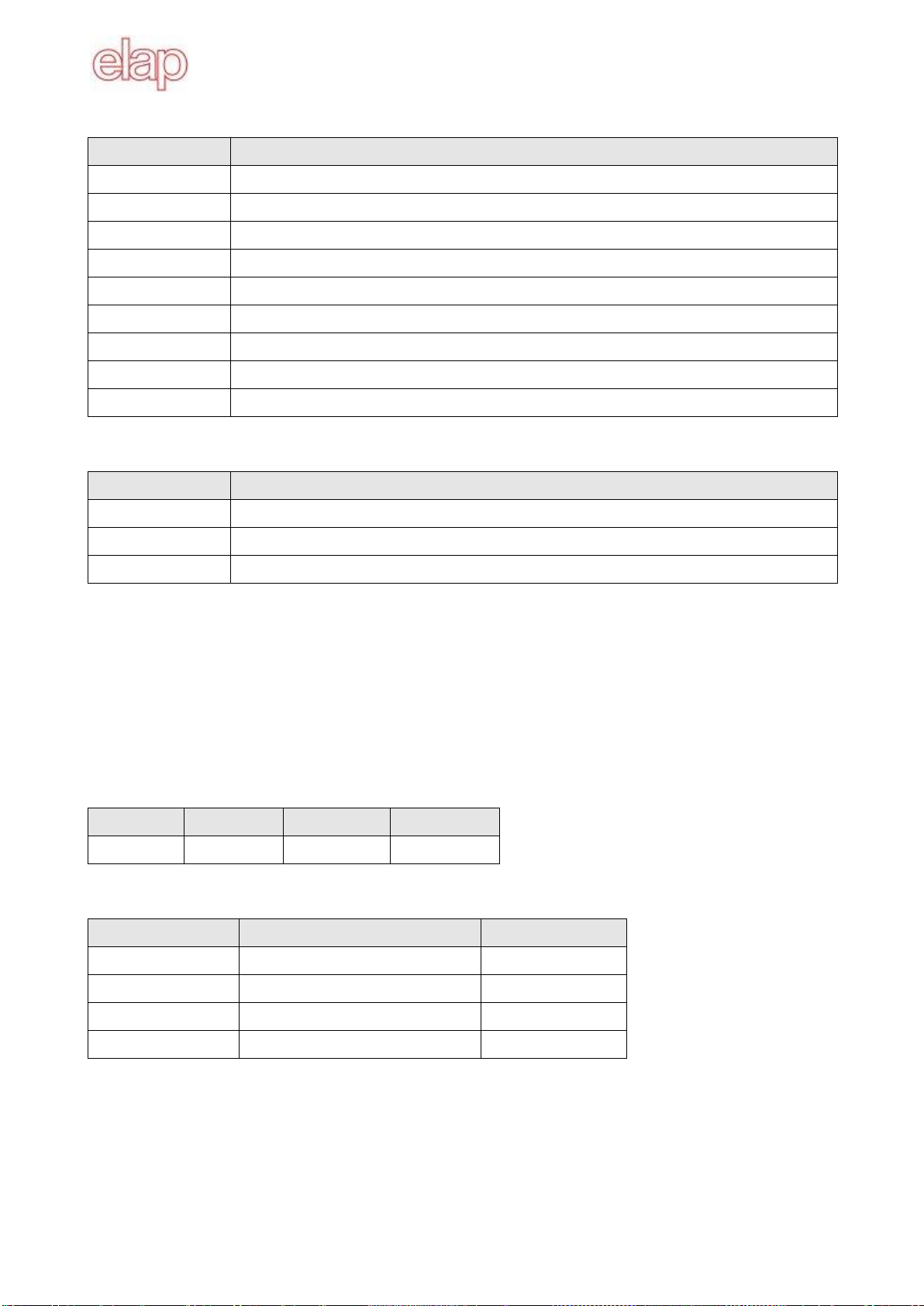
1.5 CANopen Message Structure
The first part of a message is the COB ID (Identifier).
Structure of the 11-bit COB ID :
Function code (4 bit)
Node ID (7 bit)
The function code provides information on the type of message and priority.
The lower the COB ID, the higher the priority of the message
Broadcast messages:
Function code
COB ID
NMT
0
SYNC
80H

Encoder MEM40B –MEM41B with CANopen protocol –Instruction Manual
3
MEM40B_CAN_Inglese_ul.docx
Other messages:
Function code
COB ID
Emergency
80H + Node ID
PDO1 (tx)
180H + Node
ID
PDO2 (tx)
280H + Node
ID
SDO (tx)
580H + Node
ID
SDO (rx)
600H + Node
ID
Heartbeat
700H + Node
ID
LSS (tx)
7E4H
LSS (rx)
7E5H
(tx) and (rx) from the viewpoint of the encoder
The node ID can be freely selected by means of the CANopen bus between 1 and 127. The encoders are
supplied with the Node ID 1.
This can be changed with the service data object 2101h or using LSS.
A CAN message is made up of the COB ID and up to 8 bytes of data:
COB
ID
DLC
Byte
1
Byte
2
Byte
3
Byte
4
Byte
5
Byte
6
Byte
7
Byte
8
Xxx
x
xx
xx
xx
xx
xx
xx
xx
xx
The message details are described at a later point.
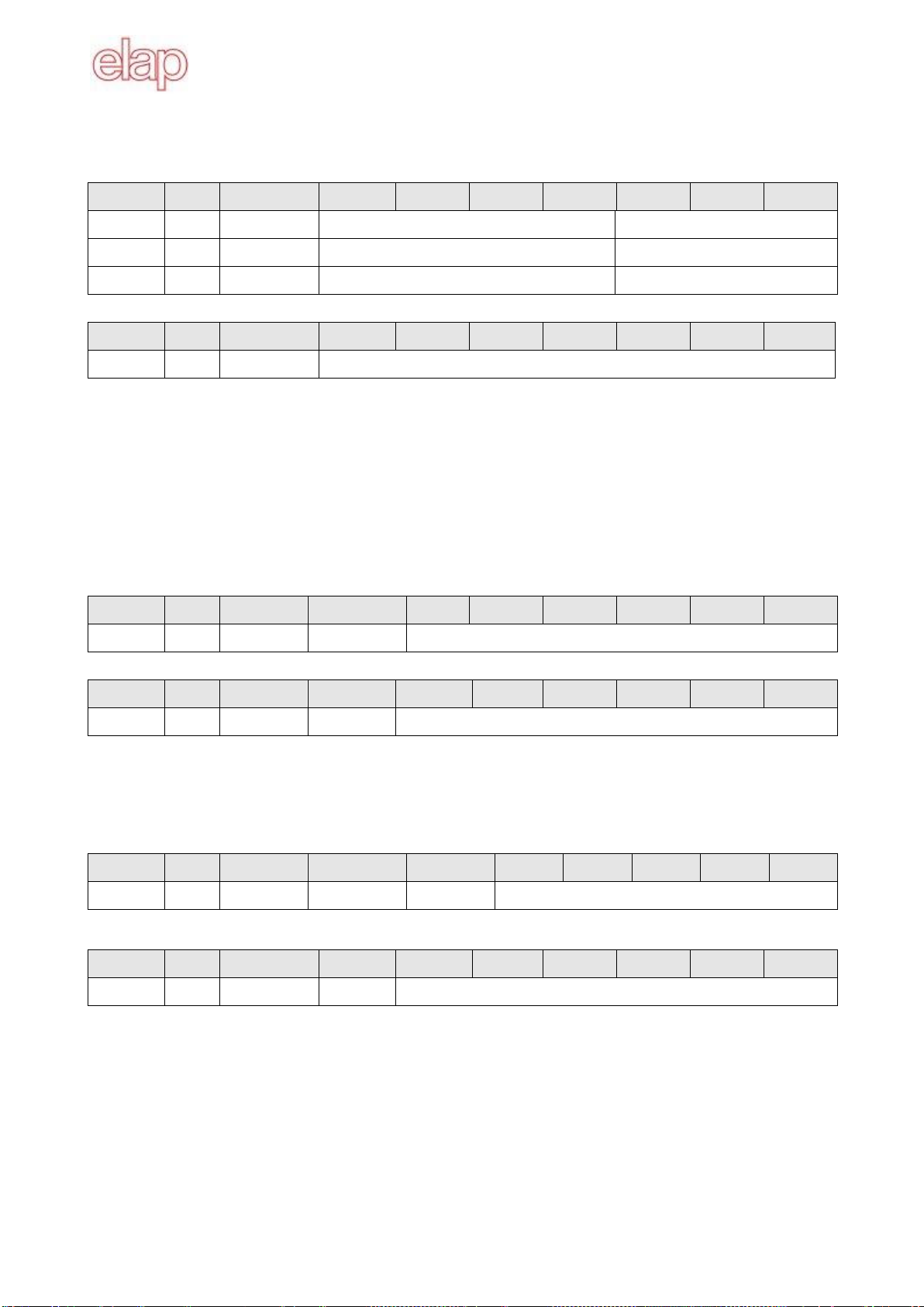
1.6 Service Data Communication
The service data objects correspond to the standards of the CiA. It is possible to access an object via
index and subindex.
The data can be requested or where applicable written into the object.
Structure of an SDO telegram:
CO
B ID
DL
C
Comman
d
Objec
t L
Objec
t H
Subinde
x
Dat
a 0
Dat
a 1
Dat
a 2
Dat
a 3
An SDO-COB ID is composed as follows:
Master Encoder : 600H + Node ID
Encoder Master : 580H + Node ID
DLC (data length code) describes the length of the telegram. This is composed as follows:
1 byte command + 2 bytes object + 1 byte subindex + no. of data bytes (0 - 4).

Encoder MEM40B –MEM41B with CANopen protocol –Instruction Manual
4
MEM40B_CAN_Inglese_ul.docx
The command byte defines whether data is read or set, and how many data bytes are involved.
SDO Command
Description
Data length
22H
Download request
Max 4 byte
Transmits parameter to encoder
23H
Download request
4 byte
2BH
Download request
2 byte
2FH
Download request
1 byte
60H
Download response
-
Confirms receipt to master
40H
Upload request
-
Requests parameter from encoder
42H
Upload response
Max 4 byte
Parameter to master with max. 4 byte
43H
Upload response
4 byte
4BH
Upload response
2 byte
4FH
Upload response
1 byte
80H
Abort message
-
Encoder signals error code to master
An abort message indicates an error in the CAN communication. The SDO command byte is 80h. The
object and subindex are those of the requested object. The error code is contained in bytes 5 –8
COB ID
DLC
Byte 1
Byte 2
Byte 3
Byte 4
Byte 5
Byte 6
Byte 7
Byte 8
580H+Node
08H
80H
Object L
Object H
Subindex
Err.0
Err.1
Err.2
Err.3
Byte 8..5 results in the SDO abort message (byte 5 LSB, .., byte 8 MSB).
The following messages are supported:
- 05040001H Command byte is not supported
- 06010000H Incorrect access to an object
- 06010001H Read access to write only
- 06010002H Write access to read only
- 06020000H Object is not supported
- 06090011H Subindex is not supported
- 06090030H Value outside the limit
- 06070010H Inconsistent data type
Some SDO examples follow.
SDO examples
Request of a value by the master to the encoder (position value, object 6004H).
COB ID
DLC
Command
Object L
Object H
Subindex
Data 0
Data 1
Data 2
Data 3
600H+Node
08H
40H
04H
60H
00H
xx
xx
xx
xx
Response by the encoder to the request for a value (the position value is composed by 4 byte).
COB ID
DLC
Command
ObjectL
ObjectH
Sub-ind
Data 0
Data 1
Data 2
Data 3
580H+Node
08H
43H
04H
60H
00H
FAH
59H
00H
00H
The encoder position is 000059FAH.

Encoder MEM40B –MEM41B with CANopen protocol –Instruction Manual
5
MEM40B_CAN_Inglese_ul.docx
Writing of a value by the master into the encoder (Position setting can be performed with preset, object
6003H, at 300H).
COB ID
DLC
Command
ObjectL
ObjectH
Sub-ind
Data 0
Data 1
Data 2
Data 3
600H+Node
08H
22H
03H
60H
00H
00H
03H
00H
00H
Encoder response to the writing of a value.
COB ID
DLC
Command
ObjectL
ObjectH
Sub-ind
Data 0
Data 1
Data 2
Data 3
580H+Node
08H
60H
03H
60H
00H
00H
00H
00H
00H
1.7 Process data communication
Process data objects are used for real time data exchange for process data, for example position or
operating status. PDOs can be transmitted synchronously or cyclically (asynchronously). The encoder
supports the PDO1 and the PDO2. Both PDOs supply the current position of the encoder and are defined
in the objects 1800H, 1801H, 1A00H, 1A01H and 6200H.
Synchronous PDO
In order to transmit the process data synchronously, a value between 1 and F0h (=240) must be written
into
the object 1800h / 1801h Subindex 2. If the value is 3, the PDO is transmitted on every third sync
telegram (if
the value 1 is entered, transmission takes place on every SYNC telegram).
In synchronous operation, the PDO is requested by the master via the Sync telegram.
COB ID
DLC
80H
00H
Cyclical PDO (asynchronous)
If you wish the PDOs to be transmitted cyclically, the value FEh must be written into the object 1800h /
1801h Subindex 2. In addition, the cycle time in milliseconds must be entered in the same object subindex
5. If the value is stored for 0 ms, the PDOs are not transmitted.
PDO1 Telegram structure
COB ID
DLC
Byte 1
Byte 2
Byte 3
Byte 4
180H+Node
04H
Xx
xx
xx
xx
PDO2 Telegram structure
COB ID
DLC
Byte 1
Byte 2
Byte 3
Byte 4
280H+Node
04H
Xx
xx
xx
xx
1.8 Emergency service
Internal device error or bus problems initiate an emergency message:
COB ID
DLC
Byte 1
Byte 2
Byte 3
Byte 4
Byte 5
Byte 6
Byte 7
Byte 8
80H+Node
08H
Err.Code L
Err.Code H
Register
Encoder MEM40B –MEM41B with CANopen protocol –Instruction Manual
6
MEM40B_CAN_Inglese_ul.docx
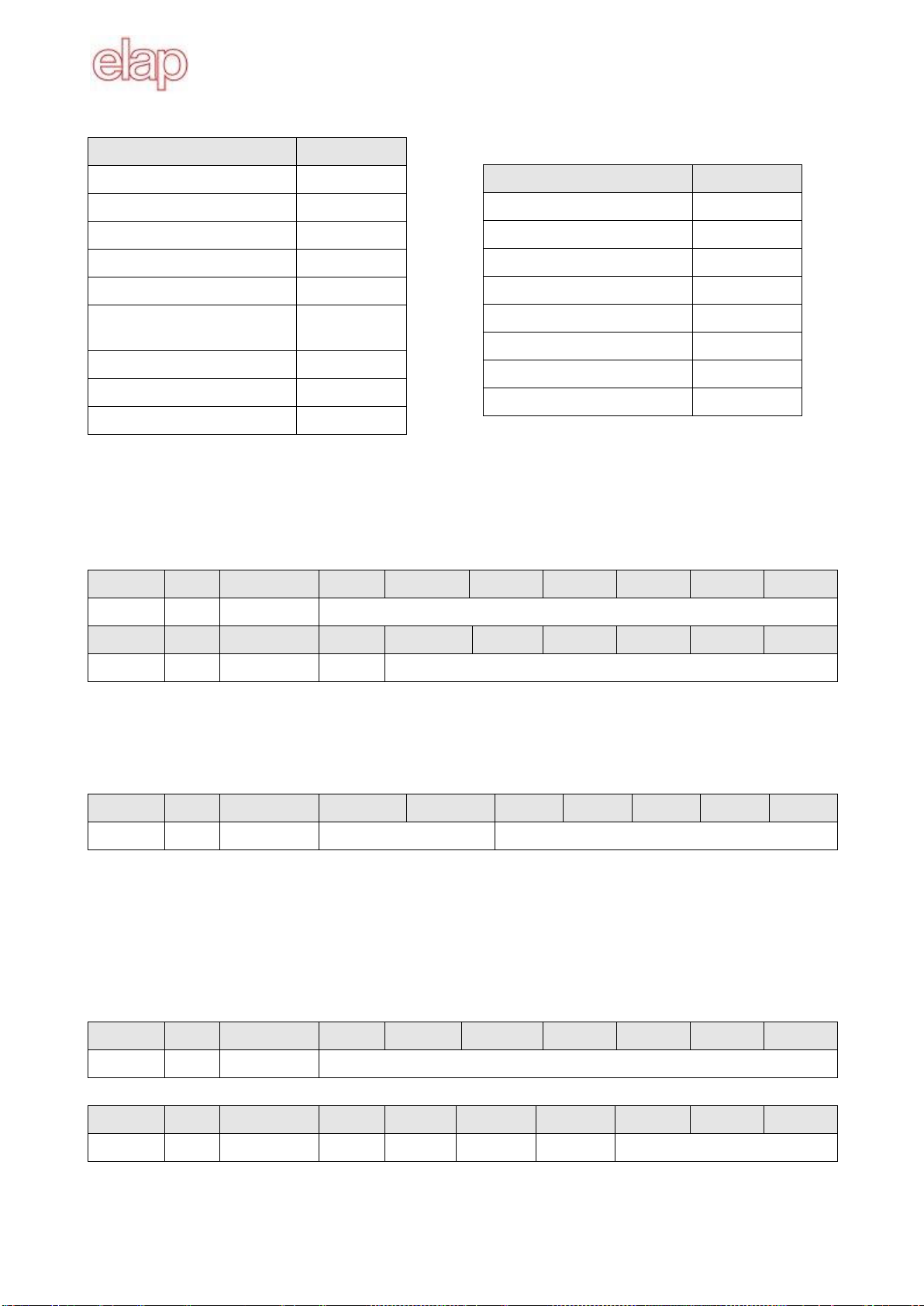
Byte 1 and 2 contain the error code.
Code
Meaning
0000H
Error reset/ no error
1000H
Generic error
6010H
Software reset (watchdog)
7320H
Position error
8110H
CAN communication error (Overrun)
8120H
CAN communication error (Transmission / Reception)
8140H
Recovered Bus-Off
FF00H
Battery low (3.2 Volts)
FF01H
Data loss
Byte 3 contains the error register (object 1001H).
Bit
Meaning
0
Generic error
4
Communication error
7
Manufacturer specific
Byte 4 to 8: not used
1.9 Network Management (NMT)
Network management can be divided into two groups.
Using the NMT services for device monitoring, bus users can be initialized, started and stopped.
In addition, NMT services exist for connection monitoring.
Description of the NMT command
The commands are transmitted as unconfirmed objects and are structured as follows:
COB ID
DLC
Byte 1
Byte 2
00H
02H
Command
Node
Command byte
Command byte
Description
State
01H
Start remote node
Operational
02H
Stop remote node
Stop
80H
Enter pre-operational mode
Pre-operational
81H, 82H
Reset remote node
Boot-up
The node number corresponds to the node ID of the required users. With node number = 0, all users are
addressed.
Following initialization, the encoder is in the pre-operational mode. In this status, SDO parameters can be
read and written. In order to request PDO parameters, the encoder must first be moved to the operational
mode status by the command Start.

Encoder MEM40B –MEM41B with CANopen protocol –Instruction Manual
7
MEM40B_CAN_Inglese_ul.docx
NMT states
Initialization
Following initialization, the encoder logs on to the CAN bus with a BootUp message. The encoder then
goes automatically to the pre-operational mode status.
The COB ID of the BootUp message is made up of 700H and the node ID.
COB ID
DLC
Byte 1
700H + Node
01H
00H
Pre-operational mode
In the pre-operational mode, SDOs can be read and written.
Operational mode
In the operational mode, the encoder transmits the requested PDOs. In addition, SDOs can be read and
written
Stopped mode
In the stopped mode, only NMT and LSS communication is possible. No SDO parameters can be read or
written.
Status change
Start command
With the start command, the encoder is switched to the operational mode status.
COB ID
DLC
Command
Node
00H
02H
01H
00H, …, 7FH
Stop command
With the stop command, the encoder is switched to the stopped mode status.
COB ID
DLC
Command
Node
00H
02H
02H
00H, …, 7FH
Pre-operational mode command
The encoder switches to the pre-operational mode status
COB ID
DLC
Command
Node
00H
02H
80H
00H, …, 7FH
Application reset command
With the reset command the encoder is re-initialized and switches to the pre-operational mode status.
COB ID
DLC
Command
Node
00H
02H
81H
00H, …, 7FH

Encoder MEM40B –MEM41B with CANopen protocol –Instruction Manual
8
MEM40B_CAN_Inglese_ul.docx
Communication reset
The encoder re-initializes the communication and switches to the pre-operational mode status.
COB ID
DLC
Command
Node
00H
02H
82H
00H, …, 7FH
Heartbeat Protocol
The encoder (Heartbeat producer) transmits the Heartbeat message cyclically with the frequency defined
in the object 1017H.
One or more Heartbeat Consumer may receive the indication. The relationship between producer and
consumer is configurable via Object Dictionary entries.
The heartbeat messages consist of the COB ID and one byte. In this byte, the NMT status is supplied.
COB ID
DLC
Byte 1
700H+Node
01H
7FH
- 00H Boot-up
- 04H Stopped state
- 05H Operational state
- 7FH Pre-operational state
In the above example the encoder is in the pre-operational state (7FH).
1.10 Layer Setting Services (LSS)
The encoder is provided with default values for node number (1) and baud rate (50 kBaud). Since several
encoders can be connected to the same CAN network with the same node number, the LSS protocol
allows to address each individual encoder. In other words different encoders with the same node number
can be connected to the system to be initialized via LSS protocol.
Both the node number and the baud rate can be modified (see Layer Setting Services and Protocol, CiA
Draft Standard Proposal 305). LSS commands can only be executed with the encoder in the stopped or
pre-operational mode state.
Message structure
COB ID:
Master Slave: 7E5H
Slave Master: 7E4H
The COB ID is followed by the LSS command specifier and seven data bytes.
COB ID
DLC
Command
Byte 1
Byte 2
Byte 3
Byte 4
Byte 5
Byte 6
Byte 7
Global Switch mode
With this command the master sets all the LSS slave in the network to the waiting status (0) or configuring
mode (1). No response follows.
COB ID
DLC
Command
Mode
Byte 2
Byte 3
Byte 4
Byte 5
Byte 6
Byte 7
7E5H
08H
04H
00H / 01H
Reserved
Encoder MEM40B –MEM41B with CANopen protocol –Instruction Manual
9
MEM40B_CAN_Inglese_ul.docx
Selective Switch Mode
With this command the master sets the LSS addressed node to the configuring mode. The response if the
addressed device follows.
COB ID
DLC
Command
Byte 1
Byte 2
Byte 3
Byte 4
Byte 5
Byte 6
Byte 7
7E5H
08H
40H
Vendor ID
reserved
7E5H
08H
41H
Product code
reserved
7E5H
08H
42H
Revision number
reserved
COB ID
DLC
Command
Byte 1
Byte 2
Byte 3
Byte 4
Byte 5
Byte 6
Byte 7
7E4H
08H
44H
Reserved
Vendor ID ELAP: 000002B4H
Product code: Encoder inside code (see label)
Revision number: Current encoder revision (see label)
Setting the node ID
After setting the encoder in the configuration mode, it is possible to modify the node ID.
Accepted node numbers: 1 to 127.
The response telegram by the slave with result in byte 1 follows (0 ok, 1 Node ID outside range).
COB ID
DLC
Command
Node
Byte 2
Byte 3
Byte 4
Byte 5
Byte 6
Byte 7
7E5H
08H
11H
01H,…,7FH
Reserved
COB ID
DLC
Command
Byte 1
Byte 2
Byte 3
Byte 4
Byte 5
Byte 6
Byte 7
7E4H
08H
11H
Result
Reserved
Setting the baud rate
After setting the encoder in the configuration mode it is possible to modify the baud rate.
The response telegram by the slave with result in byte 1 follows (0 ok, 1 baud rate outside range).
COB ID
DLC
Command
Sel,Table
Sel.Baud
Byte 3
Byte 4
Byte 5
Byte 6
Byte 7
7E5H
08H
13H
00H o 80H
xx
Reserved
COB ID
DLC
Command
Byte 1
Byte 2
Byte 3
Byte 4
Byte 5
Byte 6
Byte 7
7E4H
08H
13H
Result
Reserved
Table selection : 00H Standard CiA table
80H Vendor specific table
Encoder MEM40B –MEM41B with CANopen protocol –Instruction Manual
10
MEM40B_CAN_Inglese_ul.docx
Standard CiA table (Sel.Table = 00H)
Baud Rate
Index
1000 kBaud
0
800 kBaud
1
500 kBaud
2
250 kBaud
3
125 kBaud
4
-
5
(reserved)
50 kBaud
6
20 kBaud
7
10 kBaud
8
Elap Table (Sel.Table = 80H)
Baud Rate
Index
10 kBaud
0
20 kBaud
1
50 kBaud
2
125 kBaud
3
250 kBaud
4
500 kBaud
5
800 kBaud
6
1000 kBaud
7
Configuration saving command
With this command the master requires to save the modified data (node identification and baud rate).
The response telegram by the slave with result in byte 1 follows (0 ok, 1 saving not supported, 2
access error).
COB ID
DLC
Command
Byte 1
Byte 2
Byte 3
Byte 4
Byte 5
Byte 6
Byte 7
7E5H
08H
17H
Reserved
COB ID
DLC
Command
Byte 1
Byte 2
Byte 3
Byte 4
Byte 5
Byte 6
Byte 7
7E4H
08H
17H
Result
Reserved
Activating the new baud rate
The new baud rate set with the relevant LSS command is activated by this command. Bytes 1 and 2
contain a delay in ms. No response follows by the slave.
COB ID
DLC
Command
Byte 1
Byte 2
Byte 3
Byte 4
Byte 5
Byte 6
Byte 7
7E5H
08H
15H
Delay time (ms)
Reserved
The encoder waits the set time before re-initializing the baud rate records. Then it still waits the same time
span before sending the messages with the new baud rate to the network.
Requesting the Vendor ID
With this message the master requests the selected slave (that is in the configuration state) the vendor ID
code. The slave response with the requested data in bytes 1 to 4 follows.
COB ID
DLC
Command
Byte 1
Byte 2
Byte 3
Byte 4
Byte 5
Byte 6
Byte 7
7E5H
08H
5AH
Reserved
COB ID
DLC
Command
Byte 1
Byte 2
Byte 3
Byte 4
Byte 5
Byte 6
Byte 7
7E4H
08H
5AH
B4H
02H
00H
00H
Reserved
ELAP Vendor ID code is 000002B4H.

Encoder MEM-Bus con protocollo CANopen –Manuale di istruzioni
11
MEM40B_CAN_Inglese_ul.docx
Requesting the product code
With this message the master requests the selected slave (that is in the configuration state) the product
code. The slave response with the requested data in bytes 1 to 4 follows.
COB ID
DLC
Command
Byte 1
Byte 2
Byte 3
Byte 4
Byte 5
Byte 6
Byte 7
7E5H
08H
5BH
Reserved
COB ID
DLC
Command
Byte 1
Byte 2
Byte 3
Byte 4
Byte 5
Byte 6
Byte 7
7E4H
08H
5BH
32 bit product code
Reserved
Requesting the revision number
With this message the master requests the selected slave (that is in the configuration state) the vendor ID
code. The slave response with the requested data in bytes 1 to 4 follows.
COB ID
DLC
Command
Byte 1
Byte 2
Byte 3
Byte 4
Byte 5
Byte 6
Byte 7
7E5H
08H
5CH
Reserved
COB ID
DLC
Command
Byte 1
Byte 2
Byte 3
Byte 4
Byte 5
Byte 6
Byte 7
7E4H
08H
5CH
32 bit revision number
Reserved
Searching for a device
The encoder can be searched for in the network. The master sends the following telegrams in sequence.
The response of the relevant slave follows.
COB ID
DLC
Command
Byte 1
Byte 2
Byte 3
Byte 4
Byte 5
Byte 6
Byte 7
7E5H
08H
46H
Vendor ID
Reserved
7E5H
08H
47H
Product code
Reserved
7E5H
08H
48H
Revision number (low)
Reserved
7E5H
08H
49H
Revision number (high)
Reserved
COB ID
DLC
Command
Byte 1
Byte 2
Byte 3
Byte 4
Byte 5
Byte 6
Byte 7
7E4H
08H
4FH
Reserved

Encoder MEM-Bus con protocollo CANopen –Manuale di istruzioni
12
MEM40B_CAN_Inglese_ul.docx
2. Encoder communication profile
2.1 Overview of encoder objects
According to CiA (CAN in Automation), objects are subdivided into three groups:
• Standard objects (see DS 301, Application Layer and Communication Profile):
o1000H, 1001H, 1018H
• Manufacturer-specific objects (see DS 301):
o2000H - 5FFFH
• Device-specific objects(see DS 406, Device Profile for encoders):
oAll other objects from 1000H - 1FFFH, 6000H - FFFFH
The following table provides a summary of all SDO objects supported by the encoder.
Object Object number in Hex
Name ===
Type U/I = Unsigned/Integer, No. = number of bits, ARR = Array, REC = structure
Attr access attributes: ro = read only, wo = write only, rw = read write
Default Default value on first init
Object
Name
Type
Attr
Default
Info
1000H
Device type
U32
ro
00020196H
00010196H
Byte 0-1:
Profile 0196H = 406
Byte 2-3:
Encoder type=2(absolute, multiturn)
Encoder type=1 (absolute single turn)
1001H
Error register
U8
ro
00H
Bit0 generic error
Bit4 communication error
Bit7 battery voltage low
1003H
00H
01H
…
04H
Predefined error field
Biggest Subindex
Latest error
…
Oldest error
ARR
U8
U32
…
U32
rw
ro
…
ro
Contains the last 4 errors/warnings
Number of stored errors (0 –4)
Error or warning:
1000H Generic error
6010H Watchdog
7320H Position Error
8110H CAN Error (overrun)
8120H CAN Error (tx / rx)
8140H Recovered Bus-Off
FF00H Buffer battery ( < 3.2V)
FF01H Lost Data
1005H
COB ID SYNC message
U32
rw
00000080H
COB ID of the SYNC object
1008H
Device name
U32
ro
“MEMC”
1009H
Hardware Version
U32
ro
“n.nn”
Hardware Version in ASCII
100AH
Software Version
U32
ro
“n.nn”
Software Version in ASCII
1010H
00H
01H
Store parameters
Max sub-index
Save all parameters
ARR
U8
U32
ro
rw
01H
Single turn encoder only
Save possibility (1)
“save” (0x73617665) to save
1010H
00H
01H
Restore default parameters
Max sub-index
Restore default values
ARR
U8
U32
ro
rw
01H
Single turn encoder only
Restore possibility (1)
“load” (0x6C6F6164) to restore
1014H
COB ID emergency
U32
ro
80H+Node
COB ID of the Emergency object
1017H
Heartbeat time
U16
rw
07D0H
Heartbeat cycle time in ms

Encoder MEM-Bus con protocollo CANopen –Manuale di istruzioni
13
MEM40B_CAN_Inglese_ul.docx
Object
Name
Type
Attr
Default
Info
1018H
00H
01H
02H
03H
Identity Object
Biggest Subindex
Vendor ID
Product code
Revision No.
ARR
U8
U32
U32
U32
ro
ro
ro
ro
03H
000002B4H
Manufacturer Id (by CiA)
0AH multiturn, 0BH single turn
Current revision
1029H
00H
01H
Error behavior
Biggest Subindex
Communication error
ARR
U8
U8
ro
rw
01H
00H
Object present from 1.10 version
(see 100AH, software version)
00H change to pre-operational
01H no change of NMT state
02H change to Stop mode
1800H
00H
01H
02H
05H
Transm. PDO1 parameters
Biggest Subindex
COB ID
PDO type
Event timer
REC
U8
U32
U8
U16
ro
rw
rw
rw
05H
180H+node
FEH
0064H
PDO ID = 180H + node
Cyclic PDO
Cycle time in ms
1801H
00H
01H
02H
05H
Transm. PDO2 parameters
Biggest Subindex
COB ID
PDO Type
Event timer
REC
U8
U32
U8
U16
ro
rw
rw
rw
05H
280H+node
01H
01F4H
PDO ID = 280H + node
Synchronous PDO
Cycle time in ms
1A00H
00H
01H
PDO1 Mapping
Biggest Subindex
Content of PDO1
ARR
U8
U32
ro
ro
01H
60040020H
ro, although for CiA it is rw
Byte 0-1:
0020H = 32 bit
Byte 2-3:
6004H = object index (position)
1A01H
00H
01H
PDO2 Mapping
Biggest Subindex
Content of PDO2
ARR
U8
U32
ro
ro
01H
60040020H
ro, although for CiA it is rw
Byte 0-1:
0020H = 32 bit
Byte 2-3:
6004H = object index (position)
2100H
Baud rate
U8
rw
02H
Init is required after setting a value:
00H 10 kBit/s
01H 20 kBit/s
02H 50 kBit/s
03H 125 kBit/s
04H 250 kBit/s
05H 500 kBit/s
06H 800 kBit/s
07H 1000 kBit/s
2101H
Node ID
U8
rw
01H
Accepted values: 01H to 7FH.
Init is required after setting a value
2110H
Options
U16
rw
08H
Bit0 rotation direction
(see object 6000H, Bit0)
Bit1 not used
Bit2 scaling function
(see object 6000H, Bit2)
Bit3 Bus-Off automatic recovery
0 disabled
1enabled

Encoder MEM-Bus con protocollo CANopen –Manuale di istruzioni
14
MEM40B_CAN_Inglese_ul.docx
Object
Name
Type
Attr
Default
Info
6000H
Operational parameters
U16
rw
0000H
Bit0 rotation direction
0 clockwise rotation
1 anti-clockwise rotation
Bit2 scaling function
0 disabled
1 enabled
6001H
Resolution –single turn
U32
rw
00002000H
13 bit resolution; accepted values: 01H
to 2000H.
6002H
Overall measuring range
U32
rw
20000000H
20000000H 29 bit (multiturn)
00002000H 13 bit (singleturn)
6003H
Preset value
U32
rw
00000000H
Preset in increments
6004H
Encoder position
U32
ro
Encoder position, inclluding offset by
the preset value
6200H
Cycle time for PDO1
U16
rw
0064H
In ms, identical to object 1800H,
subindex 05H.
6500H
Operational state
U16
ro
0000H
Bit0 rotation direction
Bit2 scaling function
6501H
Max Single turn resolution
U32
ro
2000H
13 bit resolution
6502H
Revolutions number
U16
ro
Absolute number of performed rotations
6503H
Alarms
U16
ro
0000H
The following alarms are evaluated:
Bit0 Position error
6504H
Supported alarms
U16
ro
0001H
The following alarms are supported:
Bit0 Position error
6505H
Warnings
U16
ro
0000H
The following warnings are evaluated
Bit2 Watchdog (single turn)
Bit4 Battery charge (multiturn)
6506H
Supported warnings
U16
ro
0004H
0010H
The following warnings are supported
Bit2 Watchdog (single turn)
Bit4 Battery charge (multiturn)
6507H
Profile & software version
U32
ro
01000302H
Byte 0-1:
Profile version 0302H 3.02
Byte 2-3:
Software Version = 0100H 1.00
6508H
Operating time
U32
ro
00000000H
Time in 1/10 hours since last reset
6509H
Offset
U32
ro
00000000H
Offset calculated from preset
(object 6003H)
650BH
Serial number
U32
ro
FFFFFFFFH
Not used

Encoder MEM-Bus con protocollo CANopen –Manuale di istruzioni
15
MEM40B_CAN_Inglese_ul.docx
2.2 Parameters saving
The objects below are saved via object 1010H. In order to prevent unintentional saving, the message
"save" must be written in subindex 1. The saving operation is necessary to store modifications performed
in the objects below.
COB ID
DLC
Command
ObjectL
ObjectH
Sub-ind
Data0
Data1
Data2
Data3
600H+node
08H
23H
10H
10H
01H
73H „s‟
61H „a‟
76H „v‟
65H „e‟
Saved objects
Object
Sub-index
Description
Default values
1005H
00H
COB ID SYNC message
80H
1017H
00H
Heartbeat time
07D0H (2000 ms)
1029H
01H
Behavior in case of communication error
00H (change to pre-operational)
1800H
01H
COB ID PDO1
180H + node
1800H
02H
Type PDO1
FEH (PDO cyclical asynchronous)
1800H
05H
Timing PDO1
0064H (100 ms)
1801H
01H
COB ID PDO2
280H + node
Object
Sub-index
Description
Default values
1801H
02H
Type PDO2
01H (PDO synchronous))
1801H
05H
Timing PDO2
01F4H (500 ms)
2100H
00H
Baud rate index
02H (50 kbps)
2101H
00H
Node identification
01H
2110H
00H
Manufacturer options
08H
6000H
00H
Operating parameters
00H
6001H
00H
Single turn resolution
2000H (13 bit)
6002H
00H
Total measuring range
2000H
6003H
00H
Preset value
0000H
6200H
00H
PDO1 cycle time
0064H (100 ms)
6509H
00h
Offset value
0000H
The default values of the save parameters can be restored via object 1011H. In order to prevent
unintentional restoring, the message "load" must be written in subindex 1. Default values will be used by
the slave after resetting.
COB ID
DLC
Command
ObjectL
ObjectH
Sub-ind
Data0
Data1
Data2
Data3
600H+node
08H
23H
10H
10H
01H
6CH „l‟
6FH „o‟
61H „a‟
64H „d‟
3. Diagnosis and useful information
3.1 Error diagnosis field bus communication
If the encoder cannot be addressed via the CANopen bus, first of all check the terminals. If the
terminals are not in order, field bus operation should be tested next. For this purpose, a CAN
monitor is required which records CANopen communication and shows the telegrams.
The encoder should now place a BootUp message when switching the power supply off and on again.
Should no BootUp message appear, check whether the baud rates of the encoder, the CAN monitor
and the bus system are in agreement.
If you have difficulty in establishing the connection to the user, check the node number and baud rate.
The baud rate must be set the same throughout. The node number (node ID, node address) must be
between 1 and 127. Each bus user must be unambiguously assigned a node ID, i.e. it is strictly
prohibited to assign the same node ID more than once.
The node ID and baud rate can also be set conveniently using the LSS service.

Encoder MEM-Bus con protocollo CANopen –Manuale di istruzioni
16
MEM40B_CAN_Inglese_ul.docx
3.2 Error diagnosis via field bus
The encoder has at its disposal several objects and messages which transcribe the status or error status
of
the encoder.
- Object 1001H: This object is an error register for the device error status.
- Object 1003H: In this object, the last four error codes and warnings are stored.
- Object Emergency (80H + Node): High-priority error message of a user with error code and error
register.
- SDO: If SDO communication does not run correctly, the SDO response contains an error code. A list of
the possible errors follows:
o05040001H Command byte is not supported
o06010000H Incorrect access to an object
o06010001H Read access to write only object
o06010002H Write access to read only object
o06020000H Object is not supported
o06060000H FLASH memory writing/reading error (single turn only)
o06090011H Subindex is not supported
o06090030H Value outside limits
o06070010H Inconsistent data type
o08000020H Incorrect “save”/“load” code
3.3 Further useful information
Modifying the node number:
1. The node can be set in Elap specific object 2101H
2. The new node number is saved into RAM buffer.
3. On next initialization, the sensor logs on with the new node ID.
Modifying the baud rate:
1. The baud rate can be set in Elap specific object 2100H
2. The new baud rate is saved into RAM buffer.
3. On next initialization the encoder logs on with the new baud rate.
4. PAY ATTENTION: the MASTER must also be set with the same baud rate.
3.4 Signaling LEDs
The encoder is provided with a green LED (DATA), indicating the encoder state within the CANopen
network, a red LED (ERROR), indicating the error state, and a green LED (POWER) indicating the supply
state. The three signaling LEDs are shown in the picture 5.1.
DATA LED (green)
It flashes with a frequency of about 10 Hz (50 ma light, 50 ms off): the encoder is in the LSS setup
state (the red LED also flashes with the same frequency in this case).
It flashes with a frequency of about 2.5 Hz: the encoder is in the pre-operative state
It flashes every one second: the encoder is stopped.
Fixed light: the encoder is in the operative state.
ERROR LED (red)
Light off: the encoder is running correctly.
It flashes with a frequency of about 10 Hz (50 ma light, 50 ms off): the encoder is in the LSS setup
state (the green LED also flashes with the same frequency in this case).
It flashes every one second: there are errors in the CAN communication (frame errors, overrun, …)
Fixed light: the CAN controller is in the bus off state.
POWER LED (green)
Fixed light: the power supply is on.

Encoder MEM-Bus con protocollo CANopen –Manuale di istruzioni
17
MEM40B_CAN_Inglese_ul.docx
4. Applications
4.1 Reading and setting objects
In order to overwrite an object (SDO) or to read it, two telegrams always have to be transmitted: one
request from the master and one confirmation by the slave.
Example: setting an object
Setting the Heartbeat time (object 1017H, default = 2000 ms) 1500 ms (= 05DCH).
Master command telegram:
- Command: 2BH, 2 byte writing request
- Object address node: low byte first, then high byte
- Object sub-index: 0
- Value to be set: low byte first, then high byte
COB ID
DLC
Command
ObjectL
ObjectH
Sub-ind
Data0
Data1
Data2
Data3
600H+node
08H
2BH
17H
10H
00H
DCH
05H
xx
xx
The slave confirmation telegram follows:
COB ID
DLC
Command
ObjectL
ObjectH
Sub-ind
Data0
Data1
Data2
Data3
580H+node
08H
60H
17H
10H
00H
xx
xx
xx
xx
Example: reading an object
Reading the encoder position (object 6004H).
Master command message:
- Command: 40H, request for reading
- Object address node: low byte first, then high byte
- Object sub-index: 0
COB ID
DLC
Command
ObjectL
ObjectH
Sub-ind
Data0
Data1
Data2
Data3
600H+node
08H
40H
04H
60H
00H
xx
xx
xx
xx
The slave response telegram follows:
COB ID
DLC
Command
ObjectL
ObjectH
Sub-ind
Data0
Data1
Data2
Data3
580H+node
08H
43H
04H
60H
00H
04H
03H
02H
01H
The encoder value starts from the less significant byte, therefore in this case it is 01020304H ( =
16909060).
When the encoder is entered into the network, it starts with the BootUp message. The encoder must be
adjusted and configured for the environment it works in.
Changing the node ID and baud rate with LSS
The node ID and baud rate can be changed without having to use these to address the encoder. With the
LSS service, the sensors are addressed and configured via the vendor ID, product code, and revision no.
(object 1018H)
Encoder MEM-Bus con protocollo CANopen –Manuale di istruzioni
18
MEM40B_CAN_Inglese_ul.docx
Changing the node ID (node no.)
The node ID can be changed in object 2101H between 1 and 127. On the next initialization, the encoder
logs on with the new node ID.
Example: node no. Modification from 01H to 02H (writing 1 byte, value 02H)
COB ID
DLC
Command
ObjectL
ObjectH
Sub-ind
Data0
Data1
Data2
Data3
601H
08H
2FH
01H
21H
00H
02H
xx
xx
xx
The encoder confirmation telegram follows.
COB ID
DLC
Command
ObjectL
ObjectH
Sub-ind
Data0
Data1
Data2
Data3
581H
08H
60H
01H
21H
00H
xx
xx
xx
xx
Changing the baud rate
The baud rate can be changed in the object 2100H. An index is written into the object, not the effective baud
rate. On next initialization, the encoder logs on to the new baud rate. The baud rate of the master must also
be changed accordingly.
Baud rate
Index
Baud rate
0
10 kBaud
1
20 kBaud
2
50 kBaud
3
125 kBaud
4
250 kBaud
5
500 kBaud
6
800 kBaud
7
1000 kBaud
Example: baud rate modification from 02H (50 kBaud) to 03H (125 kBaud): writing 1 byte, value 03H
COB ID
DLC
Command
ObjectL
ObjectH
Sub-ind
Data0
Data1
Data2
Data3
601H
08H
2FH
00H
21H
00H
03H
xx
xx
xx
The encoder confirmation telegram follows.
COB ID
DLC
Command
ObjectL
ObjectH
Sub-ind
Data0
Data1
Data2
Data3
581H
08H
60H
00H
21H
00H
xx
xx
xx
xx
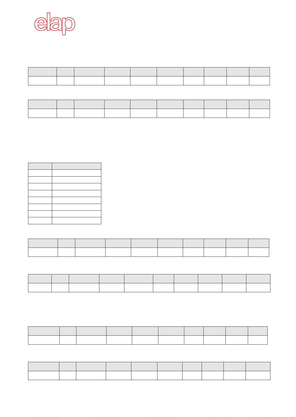
4.2 Configuration
Setting the preset value
Command message: writing 4 byte, value 0400H.
COB ID
DLC
Command
ObjectL
ObjectH
Sub-ind
Data0
Data1
Data2
Data3
600H+node
08H
23H
03H
60H
00H
00H
04H
00H
00H
The encoder confirmation telegram follows.
COB ID
DLC
Command
ObjectL
ObjectH
Sub-ind
Data0
Data1
Data2
Data3
580H+node
08H
60H
03H
60H
00H
xx
xx
xx
xx
This manual suits for next models
1
Table of contents
Other ELAP Media Converter manuals


Popular Media Converter manuals by other brands


 user manual")
Lynx Studio Technology
Lynx Studio Technology Aurora(N) user manual

CYP
CYP DCT-40 Operation manual

Extron electronics
Extron electronics IN1608 Setup guide

Hagstrom
Hagstrom KE18 user manual

Sony
Sony VGF-WA1/W - Vaio Wireless Digital Music... Specifications

urmet domus
urmet domus IPerVoice 1039 quick start guide


