ELAP MEM620-Bus User manual

1
MEM-BUS ABSOLUTE ENCODER
Instruction Manual

MEM-BUS EtherNet/IP™ENCODER Instruction Manual
ENIP_Manual_ENG 17/07/2018 2
References
THE CIP NETWORKS LIBRARY
Volume 1 –Common Industrial Protocol (CIP™), Edition 3.23
Volume 2 –EtherNet/IP Adaptation of CIP, Edition 1.23
For more information regarding ODVA, visit www.odva.org.
Registered Trademarks
RSLinx™ and RSLogix5000™ are registered trademarks of Rockwell Automation.
EtherNet/IP™and CIP™ are registered trademarks of ODVA®.
All other specified products, names and logos, serve exclusively for information purposes and may be
trademarks of their respective owners, without any special marking to indicate this.

MEM-BUS EtherNet/IP™ENCODER Instruction Manual
ENIP_Manual_ENG 17/07/2018 3
Summary
1 EtherNet/IP™...........................................................4
1.1 General information ...........................................4
1.2 CIP™ Protocol .....................................................4
1.3 The “Producer / Consumer” Model....................6
1.4 RPI Parameter.....................................................6
1.5 EtherNet/IP™ topologies ....................................6
1.6 CIP™ Object Model .............................................7
1.7 EDS File ...............................................................8
2 Installation...............................................................9
2.1 Safety .................................................................9
2.2 Transport and storage .......................................9
2.3 Mechanical assembly.........................................9
2.4 Electrical supply.................................................9
2.5 IP Address H/W Setting ...................................10
2.6 IP Address S/W Setting ....................................11
2.7 Preset button...................................................12
2.8 LED Indicators ..................................................12
3 CIP Objects ............................................................13
3.1 Identity Object –01H.......................................14
3.2 Position Sensor Object –23H ..........................15
3.3 Assembly Object –04H....................................20
3.4 TCP/IP Interface Object –F5H......................... 23
3.5 Ethernet Link Object –F6H ............................. 26
4 Configuring the encoder using RSLogix5000 ........ 29
4.1 General tab...................................................... 30
4.2 Connection tab................................................. 32
4.3 Module Info tab ............................................... 33
4.4 Internet Protocol, Port Configuration and
Network tabs ........................................................ 33
4.5 Configuration ................................................... 34
4.6 Preset function................................................. 35
TECHNICAL SPECIFICATIONS..................................... 38
ORDERING INFORMATION........................................ 39
Enclosures: dimensional drawings
MEM-BUS EtherNet/IP™ENCODER Instruction Manual
ENIP_Manual_ENG 17/07/2018 4
1 EtherNet/IP™
1.1 General information
EtherNet/IP™(Ethernet Industrial Protocol) is a frame-based computer networking technology for local
industrial area networks.
It follows the seven layers of the OSI (Open System Interconnection) model:
Layer
Function
7. Application
It supplies network services to end-user application.
6. Presentation
It handles syntax processing of message data such as format conversions and
encryption / decryption needed to support the application layer above it.
5. Session
It manages the sequence and flow of events that initiate and tear down
network connections. It is built to support multiple types of connections that
can be created dynamically and run over individual networks.
4. Transport
It delivers data across network connections. Different transport protocols
may support a range of optional capabilities including error recovery, flow
control, and support for re-transmission.
3. Network
Logical addressing is translated here into physical addressing.
2. Data Link
It checks for physical transmission errors and packages bits into data
"frames".
1. Physical
It is responsible for ultimate transmission of digital data bits from the
Physical layer of the sending (source) device over network communications
media to the Physical layer of the receiving (destination) device.
Table 1.1 –OSI model layers
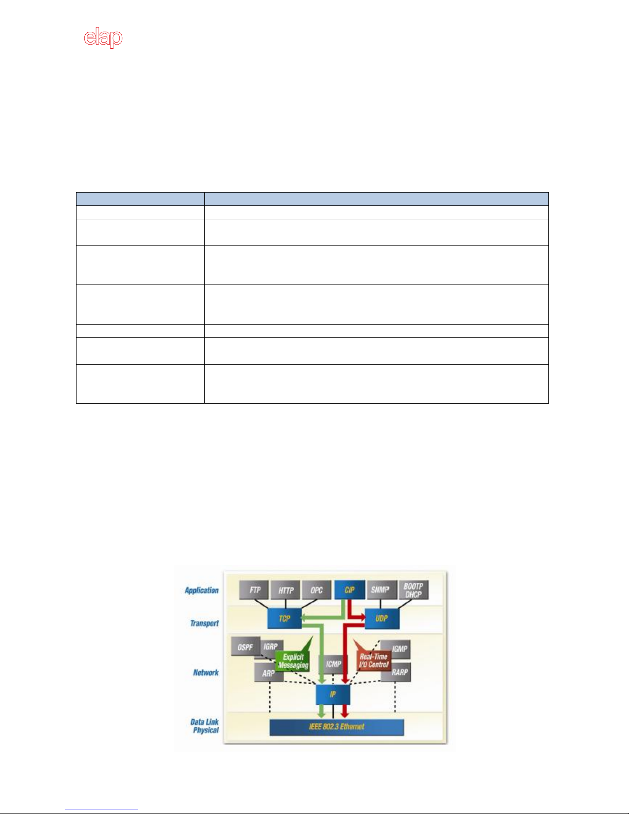
1.2 CIP™ Protocol
As an application layer (number 7 in the OSI model), EtherNet/IP uses the Common Industrial Protocol
(CIP™) for process control. ELAP MEM-BUS encoder meets all the requirements of the EtherNet/IP protocol
according to IEC61784-1 and those of the encoder profile.
The encoder is an I/O adapter in the EtherNet/IP. It receives and sends explicit and implicit messages either
cyclic or on request (polled).

MEM-BUS EtherNet/IP™ENCODER Instruction Manual
ENIP_Manual_ENG 17/07/2018 5
EtherNetIP uses TCP/IP (Transmission Control Protocol) and UDP/IP (User Datagram Protocol) for
communication.
Implicit messaging is used for real-time communication between a programmable logic controller (PLC) and
the encoder in EtherNet/IP. With implicit messaging a connection is established between exactly two
devices within the CIP™protocol to transfer, for example, I/O data such as position and velocity from the
encoder to the PLC. Implicit messaging uses UDP/IP via port 2222. As a result, a fast data rate is used.
Explicit messaging is used in EtherNet/IP for communication that does not need to take place in real time; it
is used, for example, to transfer parameters from the PLC to the encoder. Explicit messaging uses TCP/IP.
Devices that originate or use data on the network have factory-assigned media access control (MAC)
addresses for unique identification. The MAC address (MAC ID) consists of 6 bytes. The first three bytes
identify the manufacturer. The last three bytes are unique to the device.
The MAC address of ELAP MEM-BUS encoders is 60-D7-E3-1x-xx-xx.
EtherNet/IP is based on the standard Ethernet frame, which consists of the Ethernet header, the Ethernet
data, and the Ethernet trailer. The MAC IDs of the receiver (destination address) and of the source (source
address) are contained in the Ethernet header.
The Ethernet data field consists of several nested protocols:
The IP datagram is transported in the user data of the Ethernet data field.
The TCP segment or the UDP datagram is transported in the user data of the IP datagram.
The CIP™protocol is transported in the user data of the TCP segment or the UDP datagram.
CIP™is a message-based protocol that implements a relative path to send a message from the “producing”
device to the “consuming”devices. The producing device contains the path information that steers the
message along the proper route to reach its consumers. Because the producing device holds this
information, the other devices along the path simply pass it, without any need to store it.

MEM-BUS EtherNet/IP™ENCODER Instruction Manual
ENIP_Manual_ENG 17/07/2018 6
The Producer/Consumer model has two significant benefits:
You do not need to configure routing table in the bridging modules, which greatly simplifies
maintenance and module replacement.
You maintain full control over the route taken by each message, which enables you to select
alternative paths for the same end device.
1.3 The “Producer / Consumer”Model
The CIP Producer/Consumer networking model replaces the old source/destination model (Known as
master/slave). The Producer/Consumer model reduces network traffic and increases speed of transmission.
In traditional I/O systems, controllers poll input modules to obtain their input status. In the CIP system
input modules are not polled any more. Instead, they produce their data either upon a change of state or
periodically. The frequency of update depends upon the options that are chosen during configuration and
the topology of the network. Each input module, therefore, is a producer of input data, while the controller
is a consumer of data.
The controller can also produce data for other controllers to consume. The produced and consumed data is
accessible by multiple controllers and other devices over the EtherNet/IP network. This data exchange
conforms to the Producer/Consumer model.
1.4 RPI Parameter
The requested packet interval (RPI) is the update rate that is specified for a particular piece of data in the
network. This value specifies how often to produce the data for that device. For example, if RPI = 50 ms, it
means that every 50 ms the device sends its data to the controller or the controller sends its data to the
device.
RPIs are only used for devices that exchange data. For example, a ControlLogix® EtherNet/IP bridge in the
same chassis as the controller does not require an RPI because it is not a data-producing member of the
system; it is used only as a bridge to remote modules.
1.5 EtherNet/IP™topologies
ELAP MEM-BUS encoders can be connected in any of three network topologies: star, linear, or Device Level
Ring (DLR).
The linear topology uses the embedded switching capability to form a daisy chain style network that has a
beginning and an end.
Linear topology simplifies installation and reduces wiring and installation costs, but a break in the network
disconnects all devices downstream from the break.
MEM-BUS EtherNet/IP™ENCODER Instruction Manual
ENIP_Manual_ENG 17/07/2018 7
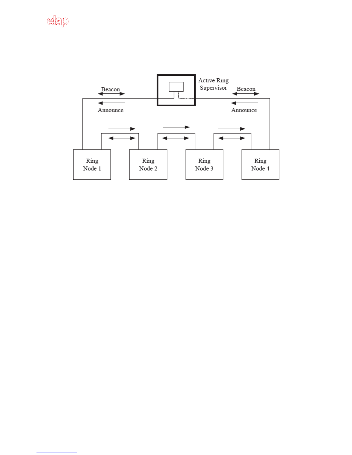
A DLR network is a single-fault-tolerant ring network that is intended for the interconnection of automation
devices. DLR topology is advantageous as it can tolerate a break in the network. If a break is detected, the
signals are sent out in both directions.
The EtherNet/IP™specification include the Device Level Ring (DLR) protocol, allowing multi-port devices to
be connected in a ring topology. DLR provides for fast network fault detection and recognition in order to
support the most demanding control applications. For example, a ring of 50 nodes implementing the DLR
protocol has a worst case fault recovery time of less than 3 ms.
The DLR protocol operates at layer 2, in the OSI model. The presence of the ring topology and the operation
of the DLR protocol are transparent to higher layers protocols, such as TCP/IP and CIP, with the exception
of a DLR object that provides a DLR configuration and diagnostic interface via CIP.
1.6 CIP™ Object Model
EtherNet/IP uses an object model for network communication wherein all functions and data of a device
are defined. CIP objects are organized in Classes, Instances and Attributes.
Class
It contains related objects of a device, which is organized in instances.
Instance
It consists of different attributes that describe the properties of the instance. Different instances of
a class have the same services, the same behavior, and the same attributes. They can, however,
have different values.
Attributes
They represent the data that a device provides over EtherNet/IP. The attributes include the current
values of a configuration or an input. Typical attributes are configuration and status information.
Services
They are used to access the classes or the attributes of a class or to generate specific events. These
services execute defined actions such as reading/writing the attributes.

MEM-BUS EtherNet/IP™ENCODER Instruction Manual
ENIP_Manual_ENG 17/07/2018 8
1.7 EDS File
The EDS (Electronic Data Sheet) file, provided by ELAP, contains all information that is related to the
measuring-system-specific parameters and the operating modes of the MEM-BUS EtherNet/IP encoders.
The EDS file is integrated using the EtherNet/IP network configuration tool to configure and place in
operation the MEM-BUS EtherNet/IP encoder.

MEM-BUS EtherNet/IP™ENCODER Instruction Manual
ENIP_Manual_ENG 17/07/2018 9
2 Installation
The encoder must be installed by qualified experts only, with net voltage off and standstill shaft. The
operating instructions of the machine manufacturer must be always observed.
2.1 Safety
Always observe prevention and safety norms during the installation and operation of the device.
Use the encoder exclusively for its intended purpose.
High voltage, current and rotating parts may cause serious or fatal injuries.
Encoders must not be operated outside the specified limited values (see detailed product
documentation).
2.2 Transport and storage
Always transport or store encoders in their original packaging.
Never drop encoders or expose them to major vibrations.
2.3 Mechanical assembly
Do not open the device.
Do not carry out mechanical changes on the device.
Avoid impacts or shocks on the housing and shaft.
Operate the device within its environmental specifications.
2.4 Electrical supply
Carry out the wiring operations exclusively with unplugged voltage supply
Do not operate on the electrical plant while the encoder is on.
Ensure that the entire plant complies with EMC requirements. The installation environment and
wiring affect the electromagnetic compatibility of the encoder. In particular:
obefore handling and installing the encoder, eliminate any electrostatic charge from your
body and from any tool that will get in contact with the device;
osupply the encoder with steady voltage free from electrical noise; if necessary, install
EMC filters for the supply input;
oalways use shielded and, if possible, twisted cables;
odo not use longer cables than necessary;
othe device cable path should be away from power cables;
oinstall the device away from possible interference sources, or shield it effectively;
oconnect the cable shield and the connector case to a protective earth and make sure that
the protective earth is free from electrical noise; the connection to earth can be carried
out at the encoder side and/or at the user side; it is up to the user to evaluate which is
the best solution to keep the electrical interference as low as possible.
MEM-BUS EtherNet/IP™ENCODER Instruction Manual
ENIP_Manual_ENG 18/09/2018 10
In order to achieve the highest possible noise immunity, the Ethernet cable screen must be connected to
ground on both ends.
In certain cases current might flow over the screen, therefore it is recommended to use equipotential
connections.
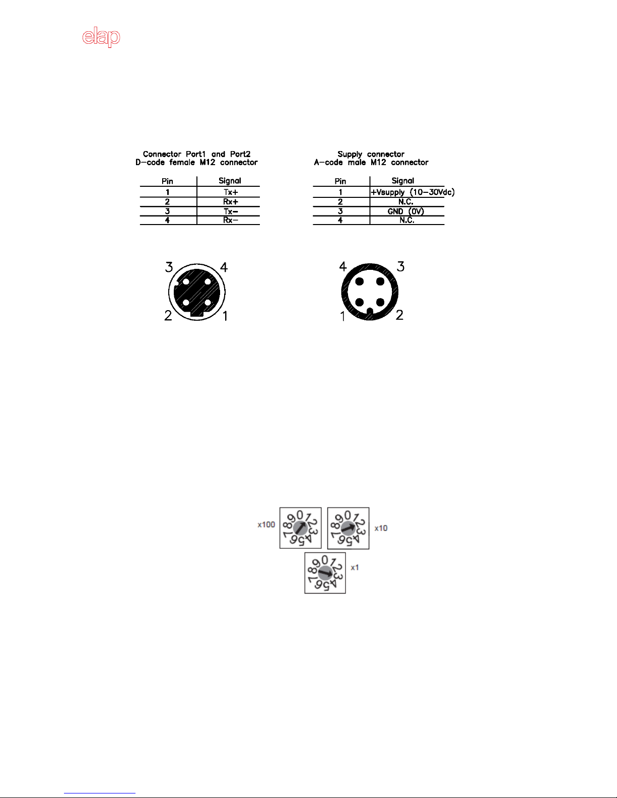
2.5 IP Address H/W Setting
The MEM-BUS encoder is provided with three rotary switches, for hardware setting of the IP address. The
IP address can be assigned using one of the two methods described below:
1. Use of the rotary switches to set the last byte value for the IP address (192.168.1.xxx).
Set the three switches to a valid address, in the range of 001 –254, and take a cycle power to the
encoder. The MEM-BUS encoder will power up with the IP address set to 192.168.1.xxx, where xxx
is given by the position of the three network address switches. In the picture below, it is xxx = 123.
2. Use the BOOTP/DHCP protocol to assign a dynamic IP address.
Set the three rotary switches to 777 (for BOOTP) or 999 (for DHCP) and then take a cycle power to
the encoder. At power up, the MEM-BUS encoder will request an IP address from a BOOTP/DHCP
server, which must be in the same network. This IP address, just assigned, can be statically
allocated by disabling the BOOTP/DHCP mode via software and setting the rotary switches to 000.
At next cycle power, no further request is sent to the BOOTP/DHCP server and the last assigned IP
is used.
Set the rotary switches to 888 to reset the encoder to factory settings. The default IP is 192.168.1.123.

MEM-BUS EtherNet/IP™ENCODER Instruction Manual
ENIP_Manual_ENG 17/07/2018 11
2.6IP Address S/W Setting
1. Set the rotary switches to 888 and take a cycle power in order to load the default factory settings.
2. Set the rotary switches to 000 and take a cycle power in order to enable S/W configuration.
3. Run RXLinx Classic Lite for Rockwell Automation networks.
ELAP MEM-BUS encoder appears in the main window, with its default IP address (192.168.1.123).
Click the right mouse button and select Module Configuration command.
In the “Port Configuration” table, it is possible to configure the TCP/IP interface (see attributes 3 e 5 of
object F5, section 3.4).

MEM-BUS EtherNet/IP™ENCODER Instruction Manual
ENIP_Manual_ENG 17/07/2018 12
2.7 Preset button
The preset button allows the user to reset the position value of the encoder. Remove the screw cover from
the back of the encoder and briefly press the button inside (see also par. 4.6, Preset Function). This button
is active only when the encoder is powered.
Note: Pressing the preset button result in a change of position reading. This can cause unexpected motion
which could result in personal injury or damage to the product or equipment.
2.8 LED Indicators
Four LEDs show the working conditions of the EtherNet/IP interface.
The Link1 and Link2 LEDs, display the status of the physical connection on the Ethernet interface.
Link1 / Link2
OFF
Power off or no Ethernet connection.
Steady Green
Ethernet connection established.
Yellow
Data transmission TxD/RxD.
Table 2.1 –Ethernet link indicators
The Mod LED shows the device status.
Mod
OFF
Power off.
Steady Green
Device in operation.
Flashing Green
Standby device, not configured, no IP address assigned.
Flashing Red
Major recoverable fault
(for example, inconsistent configuration).
Steady Red
Major unrecoverable fault, device not operational.
Flashing Green/Red
Self-test at power on.
Table 2.2 –Module status indicator
The Net LED show the status of the CIP connection.
Net
OFF
Power off or no IP address configured.
Flashing Green
Device not connected: an IP address is configured, but no CIP
connections are established.
Steady Green
Device connected: an IP address is configured, at least one CIP
connection is established.
Flashing Red
Connection timeout: a reset or a new CIP connection are
requested.
Steady Red
Error: the device has detected that its IP address is already in
use.
Flashing Green/Red
Self-test at power on.
Table 2.3 –Network status indicator
MEM-BUS EtherNet/IP™ENCODER Instruction Manual
ENIP_Manual_ENG 17/07/2018 13
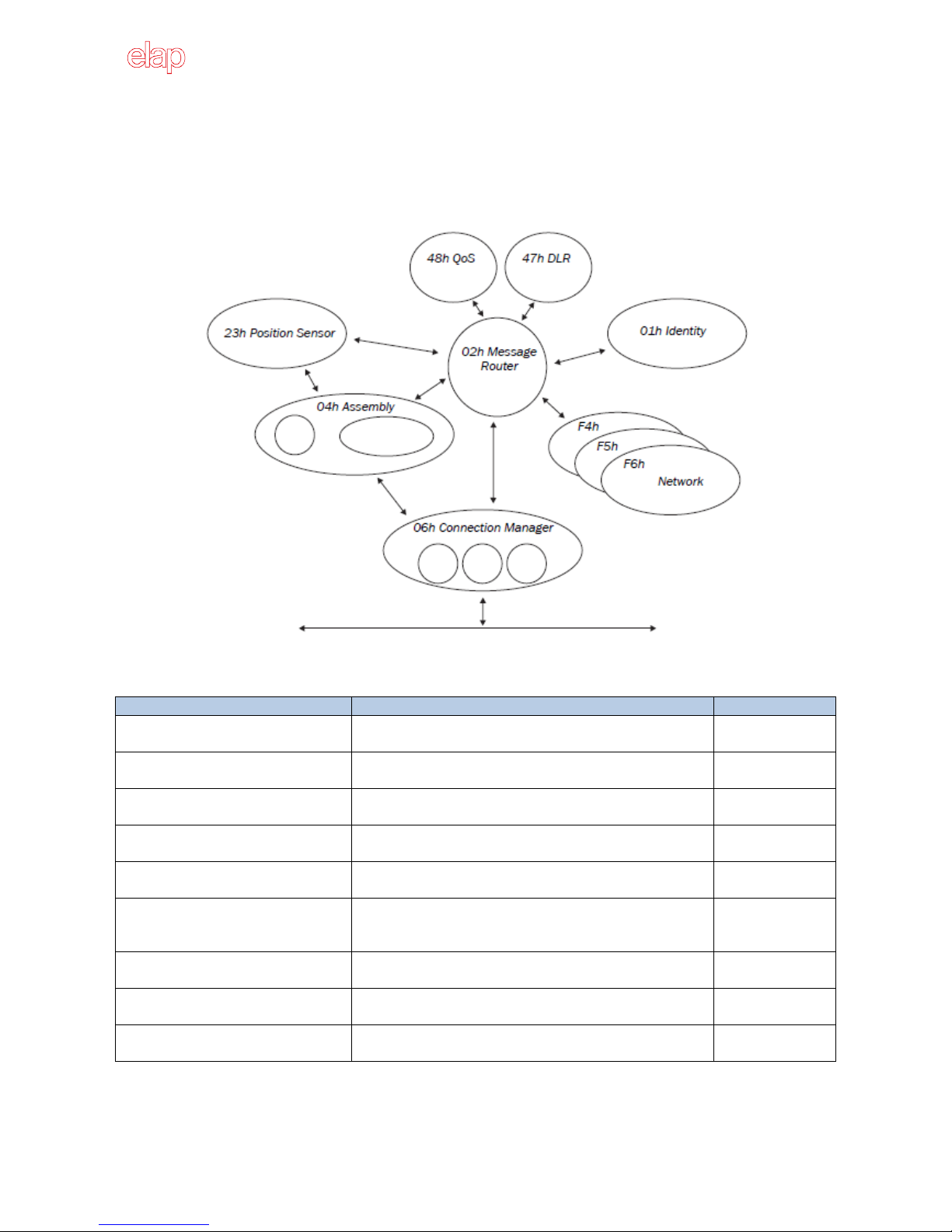
3 CIP Objects
The ELAP MEM-BUS encoder, with EtherNet/IP interface, is an absolute multiturn encoder. The encoder
profile 22H is supported, according to the CIP™ protocol specifications.
The objects implemented and their interactions are shown in the picture below.
The following table shows the implemented objects and the number of instances available for each class.
Class
Description
Instances
01H: Identity Object
It includes all device specific data (manufacturer, device
type, device status, etc.).
1
02H: Message Router Object
It includes all supported class codes of the encoder and
the maximum number of connections.
1
04H: Assembly Object
It assembles the data of several objects to one single
object (for example, position and velocity values).
4
06H: Connection Manager Object
It includes connection specific attributes for triggering,
transport, connection type, etc.
1
23H: Position Sensor Object
It includes the attributes for programming the encoder
parameters, such as scaling, counting direction, etc.
1
F5H: TCP/IP Interface Object
It includes the attributes for TCP/IP interface, such as IP
address, subnet mask, gateway and acquisition of the IP
address via BOOTP/DHCP or hardware switches, etc.
1
F6H: Ethernet Link Object
It includes connection specific attributes such as
transmission speed, interface status, MAC address, etc.
2
47H: Device Level Ring (DLR) Object
It includes status attributes and configuration attributes
for the DLR protocol.
1
48H: Quality of Service (QoS) Object
It contains mechanism for processing data streams with
different priorities.
1
Table 3.1 –Implemented CIP objects and instances

MEM-BUS EtherNet/IP™ENCODER Instruction Manual
ENIP_Manual_ENG 17/07/2018 14
3.1 Identity Object –01H
This object provides general information about the device.
Instance 0 includes the attributes of the class itself, while instance 1 includes the device identification data.
The following services are supported:
01H –Get_attribute_All (for both instances 0 and 1)
0EH –Get_Attribute_Single
05H –Reset
0 The device is re-initialized (power on).
1 The device is re-initialized (power on) and reset to the factory settings.
4BH –Flash_LEDs
9 The device executes 6 flashing sequences of its LEDS.
0 Stops the flashing.
Table 3.2 shows the supported attributes for instance 0.
INSTANCE 0, CLASS 01H
Attribute
Access
Name –Description
Data type
Value
1
Get
Revision
UINT
0001H
2
Get
Max instance
UINT
0001H
6
Get
Number ID of the last class attribute
UINT
0007H
7
Get
Number ID of the last instance attribute
UINT
0009H
Table 3.2 –Class attributes of the object 01H
Table 3.3 shows the supported attributes for instance 1.
INSTANCE 1, CLASS 01H
Attribute
Access
Name –Description
Data type
Value
1
Get
Manufacturer identification
UINT
0580H (ELAP)
2
Get
Device type
UINT
0022H (Encoder)
3
Get
Product code
UINT
000AH
4
Get
Revision
Major code
Minor code
STRUCT
USINT
USINT
01H
01H
5
Get
Device status
WORD
See table 3.4
6
Get
Serial number
UDINT
7
Get
Product name
STRING
MEM-BUS EtherNet/IP
8
Get
Present state of the device
USINT
0 Unknown
1 Device self testing
2 Standby
3 Operational
4 Recoverable fault (minor)
5 Unrecoverable fault (major)
6 –254 Reserved
255 Default (if not implemented)
9
Get
Configuration consistency
UINT
0000H
Table 3.3 –Instance 1 attributes, for object 01H

MEM-BUS EtherNet/IP™ENCODER Instruction Manual
ENIP_Manual_ENG 17/07/2018 15
The attribute number 5, which is defined as a bit string, shows the current state of the device. The
meanings of the individual bits are shown in the table below.
Bit
Name
Meaning
0
Owned
= 1 if 1 object, at least, of the device has got an owner.
This bit is set if at least a class 1 or class 3 connection was established.
1
= 0, Reserved.
2
Configured
= 1 if 1 application attribute, at least, was changed as against the default
settings.
3
= 0, Reserved.
4 - 7
Extended device status
0000 Self-test
0001 Firmware update is active
0010 1 I/O connection, at least, is in Error status (timeout detected)
0011 There are no I/O connections in the Established status
0100 The saved configuration is defective
0101 A serious error has been detected; Bit 10 or Bit 11 is set
0110 1 I/O connection, at least, is active (RUN status)
0111 1 I/O connection, at least, is in the Established status (IDLE status)
1000…1111 Values reserved for manufacturer information, not used.
8
Minor Recoverable Fault
= 1 if the device has detected a non-serious and reparable fault (for
example a I/O connection has detected a timeout).
9
Minor Unrecoverable Fault
10
Major Recoverable Fault
11
Major Unrecoverable Fault
12 - 15
Reserved, value = 0
Table 3.4 –Device status
3.2 Position Sensor Object –23H
This object provides specific data for the encoder.
Instance 0 includes the attributes of the class itself, while instance 1 includes the device specific data.
The following services are supported:
0EH –Get_Attribute_Single
10H –Set_Attribute_Single
Table 3.5 shows the supported attributes for instance 0.
INSTANCE 0, CLASS 23H
Attribute
Access
Name –Description
Data type
Value
1
Get
Revision
UINT
0002H
2
Get
Max instance
UINT
0001H
3
Get
Number of instances
UINT
0001H
6
Get
Number ID of the last class attribute
UINT
0007H
7
Get
Number ID of the last instance attribute
UINT
0064H
Table 3.5 –Class attributes of the object 23H

MEM-BUS EtherNet/IP™ENCODER Instruction Manual
ENIP_Manual_ENG 17/07/2018 16
Table 3.6 shows the supported attributes for instance 1.
INSTANCE 1, CLASS 23H
Attribute
Access
Name –Description
Data type
Value
10
Get
Position Value
DINT
11
Get
Position Sensor Type
UINT
2 Absolute encoder, multiturn
12
Get/Set
Direction Counting Toggle
BOOL
0 CW
1 CCW
14
Get/Set
Scaling Function Control
BOOL
0 Disabled
1 Enabled
16
Get/Set
Measuring Units per Span
UDINT
1 –8192
17
Get/Set
Total Measuring Range
UDINT
1 –536870912
19
Get/Set
Preset Value
DINT
0
21
Get
Position Status Register
(see values of attributes 22 and 23).
BYTE
Bit0Position is out of range
Bit1Over range
Bit2Under range
22
Get/Set
Position Low Limit
DINT
0 –536870911
23
Get/Set
Position High Limit
DINT
0 –536870911
24
Get
Velocity Value
DINT
25
Get/Set
Velocity Format
ENG UINT
1F04H step/s (default)
1F05H step/ms
1F0FH turns/min
26
Get/Set
Velocity Resolution
UDINT
1
27
Get/Set
Minimum Velocity Setpoint
DINT
-2147483648 –2147483647
28
Get/Set
Maximum Velocity Setpoint
DINT
-2147483648 –2147483647
41
Get
Operating status of the encoder
BYTE
Bit0 Direction (0 = CW)
Bit1 Scaling (0 = Disabled)
Bit2…7 Not used
42
Get
Physical Resolution Span
UDINT
8192 (13 Bit )
43
Get
Physical Resolution Number of Span
UINT
65535
44
Get
Alarms
WORD
Bit0 Position error
Bit1 Diagnostic error
Bit2…15 Not used
45
Get
Supported Alarms
WORD
0003H
46
Get
Alarm Flag
BOOL
0 No alarms
1 Alarm / error
47
Get
Warnings
WORD
Bit4 Battery charge
Bit6 Velocity below min. value
Bit7 Max Velocity exceeded
Bit10Position Limits exceeded
48
Get
Supported Warnings
WORD
04D0H
49
Get
Warning Flag
BOOL
0 No warnings
1 Warning
51
Get
Offset Value
(calculated by the Preset function).
DINT
100
Get
Rotary Switches Value
UINT
0…999
Table 3.6 –Instance 1 attributes, for object 23H
Attribute 10, Position Value
It is the output position value of the encoder, that is eventually modified by the scaling parameters (see
attributes 14, 16 and 17).

MEM-BUS EtherNet/IP™ENCODER Instruction Manual
ENIP_Manual_ENG 17/07/2018 17
Attribute 12, Direction Counting Toggle
Rotation direction, seen from the shaft side:
0 CW, the position value increases with a clockwise rotation.
1 CCW, the position value increases with a counter clockwise rotation.
Attribute 14, Scaling Function Control
0 The scaling function is disabled. Physical resolution is used for calculations (13 bit for single
turn and 16 bit for number of revolutions).
1 The scaling function is enabled. The values of attributes 16 and 17 are used for calculations.
Attribute 16, Measuring Units per Span
It sets the number of pulses for a single turn. It is active when the scaling function is enabled (that is
attribute 14 = 1). Values lower or equal to physical resolution (that is 8192 pulses per turn) are accepted.
Note: When the scaling parameters change, it is recommended to execute a Preset function (writing of
attribute 19) in order to reset the encoder and restart it from a correct position.
Attribute 17, Total Measuring Range
it sets the total measuring range for position values. It is active when the scaling function is enabled (that is
attribute 14 = 1).
The setting value is calculated as:
Measuring Units per Revolution (6001.00) x Number of Revolutions
Values lower or equal to the global physical resolution (that is 536870912) are accepted.
Note: When the scaling parameters change, it is recommended to execute a Preset function (writing of
attribute 19) in order to reset the encoder and restart it from a correct position.
Attribute 19, Preset Value
It sets the Preset value. The Preset function, that is executed when writing the attribute 19, is used to
adjust the measuring system to any position value within a range to the total measuring length - 1.
Note:
1. When the scaling parameters change, it is recommended to execute a Preset function in order to
reset the encoder and restart it from a correct position.
2. When the scaling function is disabled (attribute 14 = 0), the Preset value shall be lower than the
global physical resolution (536870912).
3. When the scaling function is enabled (attribute 14 = 1), the Preset value shall be lower than the
total resolution (attribute 17).
Attribute 21, Position Status Register
This attribute contains the actual area status of the encoder position (see attributes 22 and 23).
Bit0 = 1, if the position value is out of range (attributes 22 and 23)
Bit1 = 1, if the position value is higher than its high limit (attribute 23)
Bit2 = 1, if the position value is lower than its low limit (attribute 22)
This function allows a replacement of external proximity switches.

MEM-BUS EtherNet/IP™ENCODER Instruction Manual
ENIP_Manual_ENG 17/07/2018 18
Attributes 22 and 23, Position Low / High Limit
These attributes define a configurable work area within the measuring range.
Attribute 24, Velocity Value
It is the encoder current speed, where the format of this value is defined in attribute 25.
Attribute 25, Velocity Format
It is the format of the velocity attribute, in engineering units.
The following values are accepted:
1F04H step/s (default)
1F05H step/ms
1F0FH turns/min
Note : If this attribute is changed, both Minimum Velocity Setpoint (attribute 27) and Maximum Velocity
Setpoint (attribute 28) are reset to their default values.
Attribute 26, Velocity Resolution
It specifies the smallest incremental change of the velocity value (attribute 24).
Attributes 27 and 28, Minimum and Maximum Velocity Setpoint
The actual velocity speed limit values with minimum and maximum can be configured in attributes 27 and
28. The corresponding flags in attribute 47 (Bit6 and Bit7) are affected.
Attribute 41, Operating Status
This attribute contains the operating status of the encoder.
Bit0 Information about rotation direction is given. Position value is increasing (0) or decreasing
(1). Attribute 12 shall be used to set the counting direction.
Bit1 Information about scaling function is given (0 Disabled, 1 Enabled). Attribute 14 shall
be used to enable/disable the scaling function.
Attribute 42, Physical Resolution
This attribute contains the number of measuring steps per revolution which can be output by the
measuring system. See attributes 16 and 17 in order to set a specific resolution.
Attribute 43, Physical Resolution Number of Spans
This attribute contains the number of distinguishable revolutions that the measuring system can output.
The global physical resolution of the ELAP MEM-BUS encoder is calculated as follows
Single Turn Resolution x Number of revolutions = 8192 x 65536 = 536870912
See attributes 16 and 17 in order to set a specific total resolution.

MEM-BUS EtherNet/IP™ENCODER Instruction Manual
ENIP_Manual_ENG 17/07/2018 19
Attribute 44, Alarms
An alarm is set when the encoder has detected a status which can result in an incorrect position. As soon
as an alarm status is detected, the corresponding bit is set to logical high.
Bit0 Position error
Bit1 Diagnostic error
Bit2, …, Bit11 Reserved
Bit12, …, Bit15 Not used
Attribute 45, Supported Alarms
This attribute contains information about the alarms supported by the device.
ELAP MEM-BUS encoder supports the position error only (Bit 0); so this attribute value is 0001H.
Attribute 46, Alarm Flag
It indicates that an alarm error has occurred (attribute 44 is not zero).
Attribute 47, Warnings
Warnings are signaled by the encoder when the tolerance for certain internal parameters have been
exceeded. In contrast to alarms (attribute 44), warnings don’t imply incorrect position values.
Bit4 Battery charge too low.
Bit6 Velocity has dropped below its minimum value (attribute 27).
Bit7 Velocity has exceeded its maximum value (attribute 28).
Bit10 Position limits exceeded (see attributes 22 and 23).
Attribute 48, Supported Warnings
This attribute contains information about the warnings supported by the device.
ELAP MEM-BUS encoder supports the warnings of battery charge (Bit 4), Position limits exceeded (Bit 10)
and Velocity limits exceeded (Bit6, Bit7); so this attribute value is 04D0H.
Attribute 49, Warning Flag
It indicates that a warning error has occurred (attribute 47 is not zero).
Attribute 51, Offset Value
The offset value attribute is calculated by the preset function and shifts the position value attribute. It is
stored automatically by the device and can be read from the encoder for diagnostic purposes.
It is
Offset (attr.51) = Preset (attr.19) –Position Value (attr.10)
Attribute 100, Rotary Switches Value
The value corresponding to the position of the three rotary switches can be read for diagnostic purposes.
These rotary switches are used by the encoder only at power on. So, it is possible to change their position
when the encoder is powered, in order to check them.

MEM-BUS EtherNet/IP™ENCODER Instruction Manual
ENIP_Manual_ENG 17/07/2018 20
3.3 Assembly Object –04H
The Assembly Object binds attributes of multiple objects, which allows data to or from each object to be
sent or received over a single connection. Assembly objects can be used to bind input data or output data,
where the terms ‘input’ and ‘output’ are defined from the network’s point of view.
An input will produce data on the network, while an output will consume data from the network.
Instance 0 includes the attributes of the class itself.
The following services are supported:
0EH –Get_Attribute_Single
Table 3.7 shows the supported attributes for instance 0.
INSTANCE 0, CLASS 04H
Attribute
Access
Name –Description
Data type
Value
1
Get
Revision
UINT
0002H
2
Get
Max instance
UINT
006EH
3
Get
Number of instances
UINT
0005H
6
Get
Number ID of the last class attribute
UINT
0007H
7
Get
Number ID of the last instance attribute
UINT
0004H
Table 3.7 –Class attributes of the object 04H
The following table contains all supported instance attributes of the assembly object.
Attribute
Access
Name –Description
Data type
Value
3
Get
Data of the assembly instance
BYTE ARRAY
See table 3.9
4
Get
Number of bytes in attribute 3
UINT
See table 3.9
Table 3.8 –Assembly object, instance attributes
ELAP MEM-BUS encoder supports 4 I/O assembly instances. Assembly instances are also called connection
points. Two connection point types are defined:
O T (Originator Target = Encoder): These connection points represent output data from the
control system (PLC).
T O (Target = Encoder Originator): These connection points represent input data for control
system (PLC). The instances T O contain, for example, the position and velocity values of the
encoder.
According to the Encoder Device Profile, instances 1, 2 and 3 are provided for input data. Instance 110 is
vendor specific.
Instance 100 is defined as the configuration assembly instance. Use of this assembly instance when
establishing class 1 connections is one possibility for configuration of the encoder.
The following table shows the values of attributes 3 and 4, for the assembly instances.
Instance
Type
Attribute 3 (data)
Attribute 4 (size)
1
Input
Position Value (23H, attr.10)
4 Byte
2
Input
Position (23H, attr.10) + Alarm Flag (23H, attr.46) + Warning Flag (23H,
attr.49)
5 Byte
3
Input
Position Value (23H, attr.10) + Velocity Value (23H, attr.24)
8 Byte
100
Output
Configuration Data (see table 3.11)
28 Byte
110
Input
Position Value (23H, attr.10) + Velocity Value (23H, attr.24) + Position Status
Register (23H, attr.21) + Warnings (23H, attr.47)
12 Byte
Table 3.9 –Attributes 3 and 4 of the assembly instances
This manual suits for next models
4
Table of contents
Other ELAP Media Converter manuals


