AXIOMATIC AX141520 User manual

User Manual UMAX141520
Version 1B
Firmware 1.00
Automotive Ethernet to Ethernet Converter
USER MANUAL
P/N: AX141520

UMAX141520 Version 1B 2-19
TABLE OF CONTENT
1. GENERAL INFORMATION.................................................................................................................................. 3
1.1 Introduction....................................................................................................................................................... 3
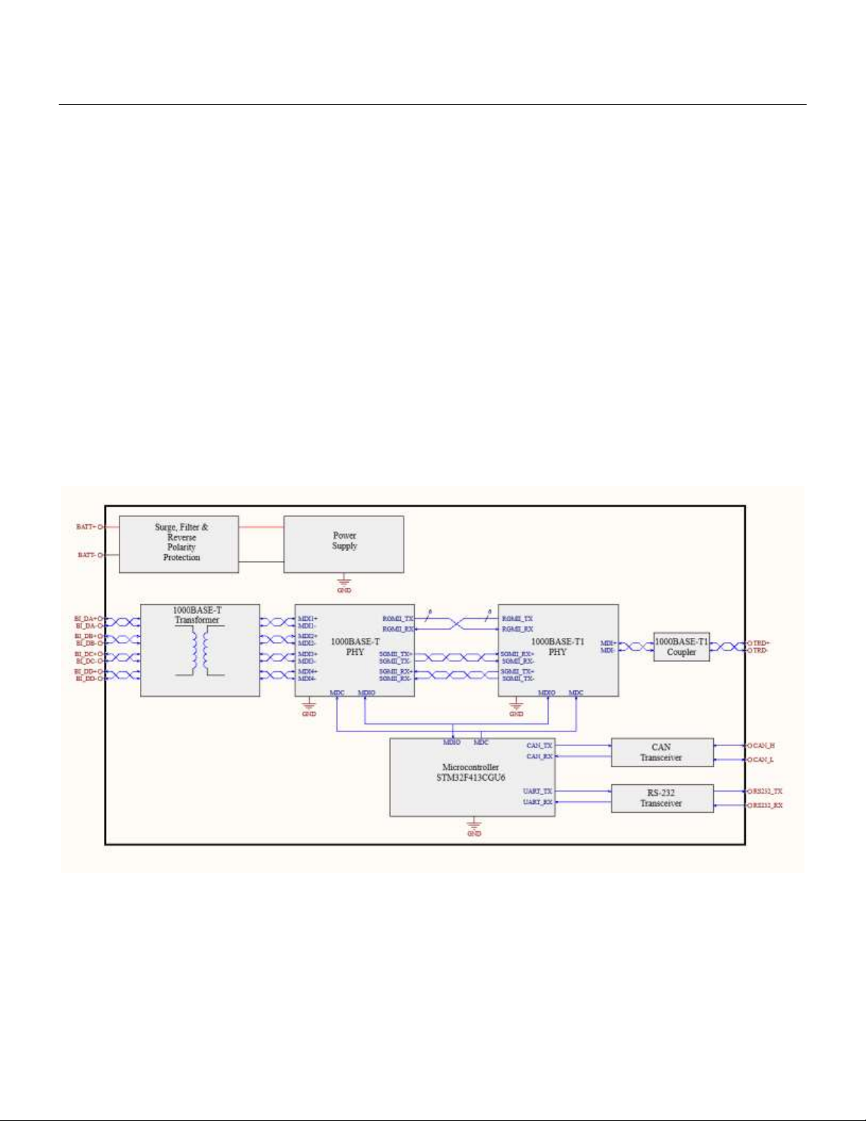
1.2 Functional Block Diagram of the Converter ...................................................................................................... 3
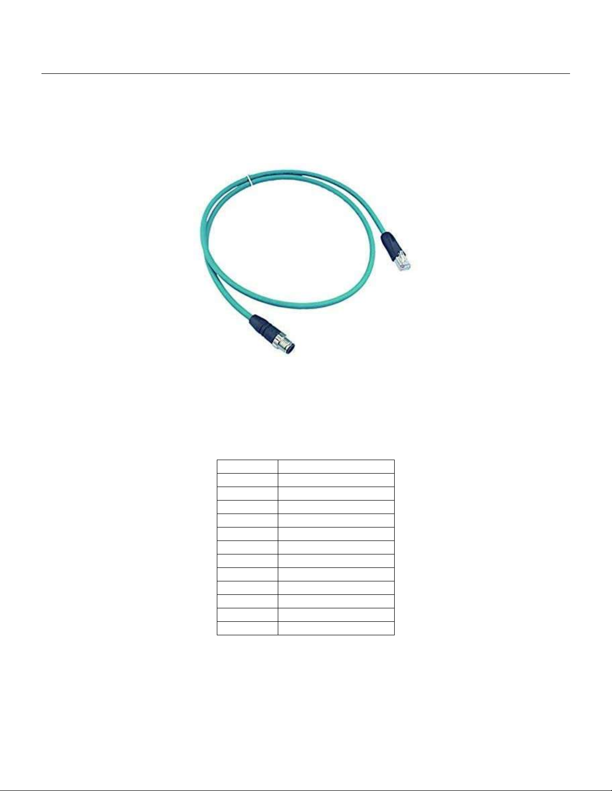
2. CONNECTORS....................................................................................................................................................... 4
2.1 M12 8-pin .......................................................................................................................................................... 4
2.2 M12 12-pin ........................................................................................................................................................ 4
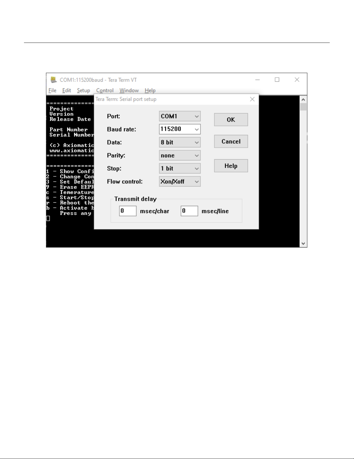
3. CONFIGURATION USING RS-232..................................................................................................................... 5
3.1 Show Configuration Parameter......................................................................................................................... 8
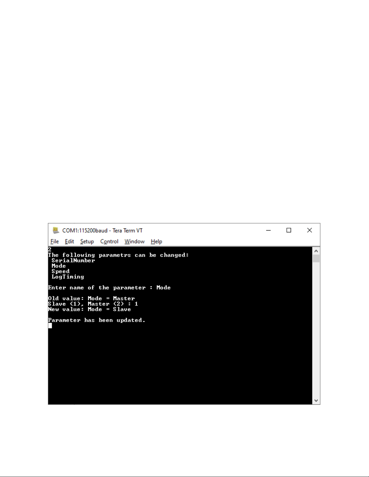
3.2 Change Configuration Parameters .................................................................................................................... 9
3.3 Set Default Configuration Parameters ............................................................................................................ 10
3.4 Erase EEPROM ................................................................................................................................................. 10
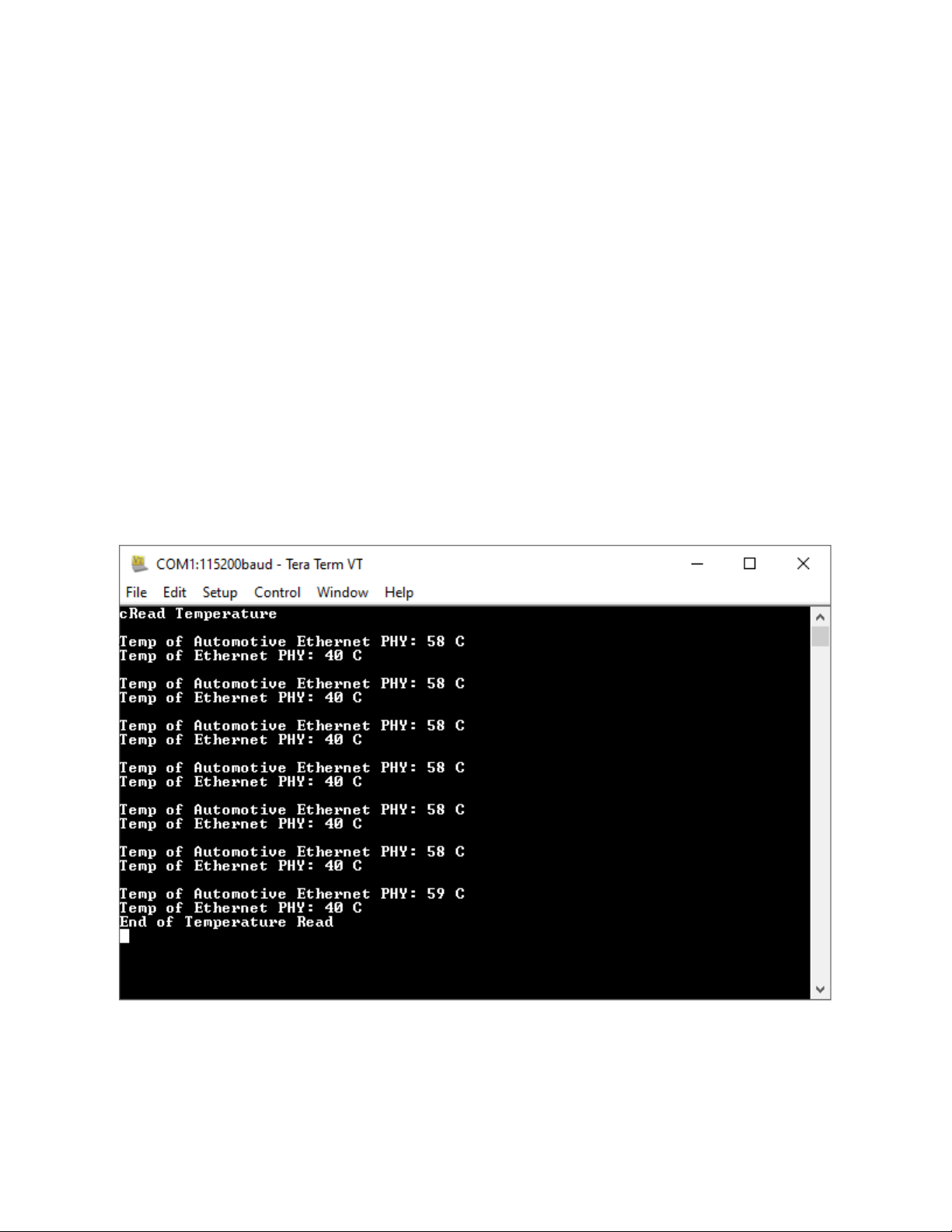
3.5 Temperature of Ethernet PHYs ....................................................................................................................... 10
3.6 Start/Stop Logs ................................................................................................................................................ 11
3.7 Reboot the Controller...................................................................................................................................... 11
3.8 Activate bootloader......................................................................................................................................... 11
3.8.1 Load New Application Firmware ............................................................................................................. 12
4. TECHNICAL SPECIFICATIONS ....................................................................................................................... 14
4.1 Power Supply Input ......................................................................................................................................... 14
4.2 Automotive Ethernet....................................................................................................................................... 14
4.3 Ethernet........................................................................................................................................................... 14
4.4 Interfaces......................................................................................................................................................... 15
4.5 General Specifications..................................................................................................................................... 15
4.6 Housing............................................................................................................................................................ 16
4.7 Electrical Connectors....................................................................................................................................... 17
5. VERSION HISTORY............................................................................................................................................ 19

UMAX141520 Version 1B 3-19
1. GENERAL INFORMATION
1.1 Introduction
The Ethernet to Automotive Ethernet Gigabit Converter, AX141520, has both Ethernet and Automotive
Ethernet Physical Layer transceivers (1000BASE-T and 1000BASE-T1 PHYs) that are used to achieve bi-
directional communication. The converter supports configuration via RS232 to update the speed
(100/1000Mbps) as well as to set the Automotive Ethernet PHY to Master/Slave mode. The AX141520 does
not store any packets and does not modify or filter any packets.
By default, both PHYs (Ethernet and the Automotive Ethernet) communicate at a speed of 1000Mbps, and
the Automotive Ethernet is configured to work in Slave mode. Status LEDs provide information on Power,
Connection Link, and Activity.
Power LED will be ON as soon as power is supplied to the converter. The Power LED is used to verify
whether power is supplied to the converter. If the proper power supply level is connected to the converter,
the Power LED will be ON; indicating the converter is ON. The AX141520 is continuously monitoring the
status of Link and Activity by reading the registers of Ethernet PHYs and will show the real-time update of
Ethernet and Automotive Ethernet Link and Activity on Link and Activity LEDs, respectively.
1.2 Functional Block Diagram of the Converter
Figure 1 Functional Block Diagram

UMAX141520 Version 1B 4-19
2. CONNECTORS
The converter has two connectors.
2.1 M12 8-pin
The M12 8-pin connector is used for the Ethernet 1000BASE-T connection. The mating harness P/N is:
AX070535.
Figure 2 M12 8-pin Ethernet Connector with RJ45
2.2 M12 12-pin
The M12 12-pin connector is used for power supply, RS-232, CAN, and Automotive Ethernet. 1 Phoenix
Contact M12 12-pin connector (A-coded). The mating harness PN is: AX070533
Table 1 M12 12-pin connector
PIN#
Description
1
BATT-
2
BATT-
3
TRD_P
4
TRD_N
5
Not Used
6
RS-232_GND
7
RS-232 TX
8
RS-232 RX
9
BATT+
10
BATT+
11
CAN_L
12
CAN_H

UMAX141520 Version 1B 5-19
3. CONFIGURATION USING RS-232
RS-232 configuration is password-protected and can be accessed through Tera Term or other serial
terminals. Tera Term Serial Port setup is shown below.
Figure 3 Tera Term: Serial port setup
Default configuration menu includes Project details like Project Name, Version number, Release Date, Part
Number, and Serial Number. The menu has 8 options as attached in the picture below. To access any of
the 8 options the one-time password is “AX141520”.

UMAX141520 Version 1B 6-19
Figure 4 Default Tera Term Menu

UMAX141520 Version 1B 7-19
To view or change the configuration, please enter the password: “AX141520”.
Figure 5 One-time password to access the Menu

UMAX141520 Version 1B 8-19
3.1 Show Configuration Parameter
Press ‘1’ to see the Configuration parameters. This option will show Serial Number, Converter Mode,
Converter Speed, and Log Timing.
If the converter Mode is “Master”, it shows that Automotive Ethernet PHY is configured to work as Master. If
the converter Mode is “Slave”, it shows that Automotive Ethernet PHY is configured to work as Slave.
Speed shows the speed of both PHYs.
Log Timing is used to see the Power and (Ethernet and Automotive Ethernet) Link logs over RS-232. Logs
are used for debugging and testing purposes. Log Timing does not affect the Converter’s working and
Master-Slave or Speed configuration of PHYs.
Figure 6 Show Configuration Parameter

UMAX141520 Version 1B 9-19
3.2 Change Configuration Parameters
Press ‘2’ to change the configuration parameters. This option gives the choice to change Serial Number,
Mode, Speed, and Log Timing. Enter the name of the parameter that needs to be changed other than Serial
Number. The option to change the Serial Number is not available for field updates.
Enter the name from the list given on the Tera term window. i.e., “Mode”, “Speed”, or “LogTiming”. Any
string entered other than given on the Tera Term window will be discarded by the Converter, as the string is
case sensitive. i.e., to change Speed, typing “speed” will have no effect as the converter is expecting for the
string “Speed”. Changing the Speed will change the Speed of both Ethernet and Automotive Ethernet
PHYs.
Type “Mode” to change the mode. Press ‘1’ to configure the Automotive Ethernet PHY in Slave mode or ‘2’
for Master mode. Changing the Mode will change the Mode of Automotive Ethernet PHY only, as normal
Ethernet PHY has Auto-negotiation enabled to negotiate the Mode.
Log Timing could be configured to have a value between 1 Second to 10 Seconds.
The Master/Slave and Speed settings will be saved. So, after reset or power cycle, the converter will have
the last configured Speed, Mode, and Log Timing.
Enter the name of the parameter: “Enter string Mode to change Mode”. To change the Speed or Log Timing
Follow the same method. As shown in the picture below.
Figure 7 Change Parameters "Master to Slave"

UMAX141520 Version 1B 10-19
3.3 Set Default Configuration Parameters
Press ‘3’ to set the default configuration parameters. This option will set the Mode and Speed to Slave and
1000Mbps respectively, as the default mode is Slave mode and default speed is 1000 Mbps.
The log timing will be also changed to the default value, which is 1 Second.
The configuration settings will be saved. So, after reset or power cycle, the converter will have the last
configured Speed, Mode, and Log Timing.
3.4 Erase EEPROM
Press ‘9’ to Erase EEPROM. Erasing the EEPROM will erase the Firmware Flags and Firmware
Configurations (Mode/Slave and Log Timing) stored in EEPROM. So, in the next power cycle, the firmware
will store default Configuration parameters and Firmware Flags.
This is useful while doing the Firmware Version update, to erase the old version number stored in EEPROM
and save the new version number.
3.5 Temperature of Ethernet PHYs
Press ‘c’.to read the internal temperature of both the PHYs in Celsius.
Figure 8 Temperature of PHYs in Fahrenheit

UMAX141520 Version 1B 11-19
3.6 Start/Stop Logs
Press ‘s’ to start or stop the debug logs. Starting the debug logs will print the supplied voltage to the Unit
and Ethernet and Automotive Ethernet Link status on Tera Term, as per the Log Timing configuration. i.e., If
Log Timing is 1 Second, the converter will print the debug logs every second. Pressing ‘s’ again will stop the
logs.
Figure 9 Status Log
3.7 Reboot the Controller
Press ‘r’ to reboot the converter. This will simply restart the converter. Rebooting the converter will not
change the Mode or Speed of the converter. This option is useful to restart the converter through Tera
Term.
3.8 Activate bootloader
Press ‘b’ to activate the bootloader. To activate the bootloader please enter the password: “StartBL”.
As shown in the picture below, it will Reboot the convert and the Bootloader will be started. The bootloader
ID will be printed, and the bootloader will be activated. Bootloader Menu will give options to load a new
Firmware file, to read the current Firmware file, or to reboot the convert to close the bootloader and start the
Firmware again.

UMAX141520 Version 1B 12-19
Figure 10 Bootloader Menu
3.8.1 Load New Application Firmware
Press ‘1’ to upload new Firmware. The firmware will be erased. Type ‘Yes’ only if a valid firmware file is
received from Axiomatic Technologies to reflash. Bootloader flags will be erased. Which shows that
firmware is erased.
Ready to flash new firmware? Yes/No: “Enter Yes or No and press enter”
Use Menu: File->Send File... with XON/XOFF control. Select the Firmware File (AF-20023-xx.yy.af) and
select the "Binary File" options, where xx.yy represents the major and minor version of the firmware,
respectively.

UMAX141520 Version 1B 13-19
Figure 11 Step 1: File->Send File
Figure 12 Select "Binary" and Select the Firmware File

UMAX141520 Version 1B 14-19
4. TECHNICAL SPECIFICATIONS
4.1 Power Supply Input
Table 2 Power Supply Input
Power Supply Input - Nominal
12V, 24Vdc nominal (9…36VDC power supply range)
Protections
Surge protection is provided.
Reverse polarity protection up to -50V is provided.
Input overvoltage (45V) and input undervoltage (6V) protection are
provided.
The unit is designed for 12Vdc based load dump.
Power Consumption
135 mA @ 12V; 70 mA@ 24V typical
Power LED
GREEN = Power ON
4.2 Automotive Ethernet
Table 3 Automotive Ethernet Parameters
Port Type
1 port
100BASE-T1//1000BASE-T1 (IEEE 802.3 bw/bp compliant
Automatic Polarity Correction
Default configuration: Slave (Master mode is configurable via serial
interface)
PHY
Marvell 88Q2112 (100BASE-T1//1000BASE-T1)
LED’s
2 GREEN LEDs for Automotive Ethernet
Automotive Ethernet LEDs:
ON
BLINK
OFF
LED [0]: Link
Link
No Link
LED [1]: Activity
Activity
No Activity
Activity:
Receive/Transmit
Protection
ESD protection for signal lines
Protocol
Automotive Ethernet
Ethernet IEEE 802.3bw for 100BASE-T1
Ethernet IEEE 802.3bp for 1000BASE-T1
4.3 Ethernet
Table 4 Ethernet Parameters
Port Type
1 port
100BASE-TX/1000BASE-T (IEEE 802.3 compliant)
Auto-Negotiation
Automatic Polarity Correction
MDIX
Auto-MDI/MDIX (crossover)
PHY
Marvell 88EA1512 (100BASE-TX/1000BASE-T)

UMAX141520 Version 1B 15-19
Connections
Connec
tor pins
MDI
MDIX
(Crossover)
6/4
BI_DA±
BI_DB±
5/8
BI_DB±
BI_DA±
1/7
BI_DC±
BI_DD±
2/3
BI_DD±
BI_DC±
Protocol
Ethernet IEEE 802.3
Protection
ESD protection for signal lines
4.4 Interfaces
Table 5 Converter Interfaces
CAN
1 CAN (SAE J1939) port
User Interface for Reflashing
RS-232
RS-232
1 3-wire RS-232 port
Maximum Baud Rate: 400 kBit/s
ESD and EFT protection for signal lines
RS-232 User Interface
Any terminal emulator that supports serial communication.
Configurability
Used to configure the unit as Slave (default) or Master functionality
4.5 General Specifications
Table 6 General Specifications
Functionality
Model AX141520 can be configured to acts as a master or a slave.
Microprocessor
STM32F413CGU6
Compliance
CE marking pending
Vibration
Random Vibration: Z-axis tracked vehicle profile (5 hr/axis in all 3 axes)
Sinusoidal Component: 8.9 G Sine sweep, 2.5 hr/axis in all 3 axes
Shock
50 g, 5 impacts per test, 6-20 ms impact duration
Operating Conditions
-40 to 60C (-40 to 140F)
Please see temperature ratings of cables under Mating Wire
Harnesses.
Storage Temperature
-40 to 85C (-40 to 185F)
Protection
IP67
Weight
0.20 lb. (0.091 kg)
Installation
The typical maximum wire harness length for Automotive Ethernet
cabling is 15 m.
Enclosure and Dimensions
See dimensional drawing, Figure 2.0 and 3.0.
Nylon 6/6, 30% glass fill
UL 94V-0
Ultrasonically welded

UMAX141520 Version 1B 16-19
4.6 Housing
Figure 13 Dimensional Drawing

UMAX141520 Version 1B 17-19
4.7 Electrical Connectors
Table 7 Electrical Connections and Connectors
Electrical Connections
POWER/ Automotive Ethernet/ RS-232 / CAN Connector
1 Phoenix Contact M12 12-pin connector (A-coded), Female P/N: 1441833
(Connector J2 on the left-hand side)
PIN
#
Description
1
BATT-
2
BATT-
3
TRD_P
4
TRD_N
5
Not Used
6
RS-232_GND
7
RS-232 TX
8
RS-232 RX
9
BATT+
10
BATT+
11
CAN_L
12
CAN_H
Ethernet Power Connector
1 Phoenix Contact M12 8-pin connector (A-coded), Female, P/N: 1406117
(Connector J1 on the right-hand side)
PIN
#
Description
1
BI_DC_P
2
BI_DD_P
3
BI_DD_N
4
BI_DA_N
5
BI_DB_P
6
BI_DA_P
7
BI_DC_N
8
BI_DB_N
Mating Connectors
Mating connectors should meet the following standard for M12 Connectors,
IEC 61076-2-101:2012. They should be A-coded.
Mating Wire Harnesses
The following part numbers are available from Axiomatic.
AX070535: Ethernet Cable 2 m (6.5 ft.), 8-pin M12 A-coded, Ethernet Jack
Note: Cable supplier is Phoenix Contact Network cable NBC-M12MR/2,0-
94B/R4AC US –1406112. The M12 connector on the harness assembly is
rated for -20 to +85C and the RJ45 ethernet jack is rated as -20 to +60C.
AX070533: Cable 1.5 m (5 ft.), 12-pin M12 A-coded, Unterminated Leads

UMAX141520 Version 1B 18-19
Figure 14 AX070535 Mating Cable
Figure 15 AX07533 Mating Cable

UMAX141520 Version 1B 19-19
5. VERSION HISTORY
Version
Date
Author
Modifications
-
April 8th, 2021
Meera Patel
Initial Draft
1.0
February 4th, 2022
Meera Patel
Completed the User Manual
1A
February 4th, 2022
Meera Patel
Updated the Firmware Reflashing interface
1B
September 7, 2022
Amanda Wilkins,
Peter Yin
Updated PHY spec and user interface details in
Specifications section

Copyright 2022
OUR PRODUCTS
AC/DC Power Supplies
Actuator Controls/Interfaces
Automotive Ethernet Converters
Battery Chargers
CAN Controls, Routers, Repeaters
CAN/WiFi, CAN/Bluetooth, Routers
Current/Voltage Converters
DC/DC Power Converters
Engine Temperature Scanners
Ethernet/CAN Converters,
Gateways, Switches
Fan Drive Controllers
Gateways, CAN/Modbus Protocols
Gyroscope Inclinometers
Hydraulic Valve Controllers
Inclinometers, Triaxial
I/O Controls
LVDT Signal Converters
Machine Controls
Modbus Controls
Motor Controls
Power Supplies, DC/DC, AC/DC
PWM Signal Converters/Isolators
Resolver Signal Conditioners
Service Tools
Signal Conditioners, Converters
Strain Gauge CAN Controls
Surge Suppressors
OUR COMPANY
Axiomatic provides electronic machine control components to the off-highway,
commercial vehicle, electric vehicle, power generator set, material handling,
renewable energy and industrial OEM markets. We innovate with engineered
and off-the-shelf machine controls that add value for our customers.
QUALITY DESIGN AND MANUFACTURING
We have an ISO9001:2015 registered design/manufacturing facility in Canada.
WARRANTY, APPLICATION APPROVALS/LIMITATIONS
Axiomatic Technologies Corporation reserves the right to make corrections,
modifications, enhancements, improvements, and other changes to its products
and services at any time and to discontinue any product or service without
notice. Customers should obtain the latest relevant information before placing
orders and should verify that such information is current and complete. Users
should satisfy themselves that the product is suitable for use in the intended
application. All our products carry a limited warranty against defects in material
and workmanship. Please refer to our Warranty, Application
Approvals/Limitations and Return Materials Process at
https://www.axiomatic.com/service/.
COMPLIANCE
Product compliance details can be found in the product literature and/or on
SAFE USE
All products should be serviced by Axiomatic. Do not open the product and
perform the service yourself.
This product can expose you to chemicals which are known in the
State of California, USA to cause cancer and reproductive harm. For
more information go to www.P65Warnings.ca.gov.
SERVICE
All products to be returned to Axiomatic require a Return Materials
following information when requesting an RMA number:
• Serial number, part number
• Runtime hours, description of problem
• Wiring set up diagram, application and other comments as needed
DISPOSAL
Axiomatic products are electronic waste. Please follow your local environmental
waste and recycling laws, regulations and policies for safe disposal or recycling
of electronic waste.
CONTACTS
Axiomatic Technologies Corporation
5915 Wallace Street
Mississauga, ON
CANADA L4Z 1Z8
TEL: +1 905 602 9270
FAX: +1 905 602 9279
www.axiomatic.com
Axiomatic Technologies Oy
Höytämöntie 6
33880 Lempäälä
FINLAND
TEL: +358 103 375 750
FAX: +358 3 3595 660
www.axiomatic.com
Table of contents
Other AXIOMATIC Media Converter manuals
Popular Media Converter manuals by other brands

BASETech
BASETech BTNA-70 Operating instruction

Patton electronics
Patton electronics 2089 user manual

Maxim
Maxim MAX12557 Specifications

Bel Canto
Bel Canto One Series DAC 1.5 user guide

Atlona
Atlona AT-HD-AVSC Operation manual

Link electronics
Link electronics SD SDI Video Closed Caption Encoder/Decoder... Specifications