Elastec MediBurn30 Installation and operating instructions
MEDIBURN30 D-115 Rev 010
www.elastec.com
OPERATION & SERVICE MANUAL
MEDIBURN30

MEDIBURN30 2 D-115 Rev 010
www.elastec.com

MEDIBURN30 3 D-115 Rev 010
www.elastec.com
Introduction, Contact Information .....................................................................4
Product Description............................................................................................5
General Information............................................................................................6
Control Panel.......................................................................................................7
How it Works .......................................................................................................8
Butterfly Assembly ...........................................................................................10
Door Lock Motor Assembly .............................................................................11
Surge Protector Assembly ...............................................................................12
Burnables ..........................................................................................................13
Safety Instructions............................................................................................14
Preparing for Disposal......................................................................................15
Cycle Completion..............................................................................................17
Ash Removal .....................................................................................................17
Error Codes .......................................................................................................18
Troubleshooting Guide.....................................................................................19
Installing Gauge, Setting Fuel Pressure .........................................................23
Maintenance ......................................................................................................24
Storage...............................................................................................................24
Fuse Identification ............................................................................................25
Controller Parts List..........................................................................................26
Chamber Parts List #1 ......................................................................................27
Chamber Parts List #2 ......................................................................................28
Chamber Brick Assemblies..............................................................................30
Chamber Brick Assembly Parts List ...............................................................31
Burner Drawing, Parts List...............................................................................32
Under Air Parts List ..........................................................................................33
Spare Parts List.................................................................................................33
Warranty ............................................................................................................34
Items Not Covered by Warranty.......................................................................35
TABLE OF CONTENTS

MEDIBURN30 4 D-115 Rev 010
www.elastec.com
This manual contains information on the Elastec MediBurn30, manufactured
by Elastec, Inc. All data in this publication is based on the latest product
information.
Elastec reserves the right to make changes at any time without notice and
without incurring any obligations. If a problem is encountered, or if you have
questions about your Elastec equipment, please call one of our consultants at
+1 (618) 382-2525.
Elastec products are USA-designed and built to provide safe and dependable
service when operated according to instructions. Please remember that
working with an incineration device can be dangerous. Read and understand
this manual before operating this system. Failure to do so may result in
personal injury and/or equipment damage.
Your MediBurn30 serial number is _________________________________
SERIAL NUMBER MUST BE INCLUDED WHEN ORDERING PARTS.
INTRODUCTION
1
CONTACT INFORMATION
Elastec, Inc. Telephone: +1 (618) 382-2525
1309 West Main Street Fax: +1 (618) 382-3610
USA Website: www.elastec.com

MEDIBURN30 5 D-115 Rev 010
www.elastec.com
PRODUCT DESCRIPTION
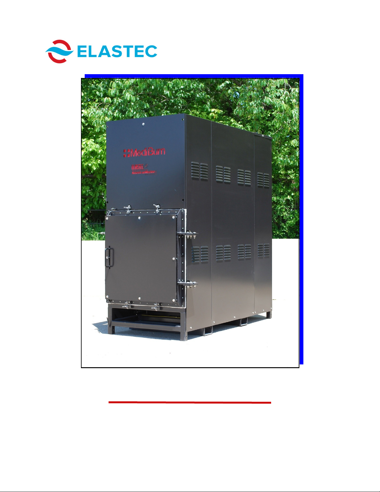
The Elastec MediBurn30 is a portable, small batch medical waste incinerator.
It enables small hospitals, clinics and laboratories to dispose of medical waste
in a safe and efficient manner. The MediBurn30 is designed to be easily and
safely operated by existing personnel with minimal training. The MediBurn30
can be used at any convenient location on existing property. Before using the
MediBurn30, the operator should read and follow the instructions in this
manual.
Length:
Width:
Height:
Weight:
Fuel Tank Capacity:
Primary Chamber Volume:
Suggested Load Volume:
79” (201 cm)
34” (86 cm)
82” (208 cm) without stack
100” (254 cm) with stack
2,440 lbs (approx. 1,107 kg)
40 gallons (151 litres)
13 cu ft (.37 cu m)
10.5 cu ft (.30 cu m)
SPECIFICATIONS
Electric:
Fuel:
Variable
2-3 gallons/hour (7-11 litres/hour)
FUEL AND POWER CONSUMPTION
Incinerates up to 30 kg per hour
Modulating burners & under-air technology provide up to 50%
fuel savings.
Ready to use upon delivery
Updated electronic control system with multiple languages
available
Dual chamber combustion & high exhaust temperatures in
excess of 1000 degrees C
Safety features such as door lock and sensor.
Replaceable ceramics
FUEL AND POWER CONSUMPTION

MEDIBURN30 6 D-115 Rev 010
www.elastec.com
CAUTION: Operators must wear gloves and safety glasses while operating unit.
CAPACITY
One MediBurn30 is capable of disposing of 10.5 cubic feet (.030 cubic meters)
of medical waste per load. Since there is a broad range of densities in waste
materials, the actual amount may vary. The waste is reduced to approximately
5% of its original volume. Ash is removed by means of a special rake (supplied
with the unit) and can be emptied directly into appropriate containers.
HOOK-UP
Electrical: In some cases, plugs may have to be installed on the end of the wires
extending from the unit to be compatible with local electrical fittings.
Fuel: There are two options for the supply of diesel to the unit:
Gravity-fed system: A large fuel tank supplies the unit. The bottom of the
tank should be higher than the top of the burner on the secondary chamber.
Mounted tank: Fuel supply is mounted under the unit with a fuel pump and
return line.
CONTROL PANEL OPERATION
The burn times are adjusted using the UP and DOWN arrows on the controller
located on the control panel (see Page 7). When the cycle time is chosen, push
the START button and the MediBurn30 will begin its operating cycle. To change
the cycle time, push the STOP button and change the cycle time. Then restart
the unit.
COMPLETE CYCLE
Unit is switched on, burn chamber door will lock and the 30-second purge
begins (fans only).
7-minute pre-heat (secondary chamber burner fires and begins the pre-heat
process).
Burn cycle begins.
After the firing cycle is complete, blowers in both primary and secondary
chambers blow cool air until the temperature of the unit is 300 degrees
Celsius. If the temperature rises again, blowers will be activated cyclically
until the temperature remains below 300 degrees Celsius.
OPERATING TEMPERATURES
Temperature readouts are visible on the control panel. The unit is designed to
preheat the secondary chamber for 7 minutes before incineration begins in the
primary chamber. Exhaust temperatures are automatically controlled to range
from 1000 degrees Celsius to 1025 degrees Celsius during the burn cycle.
Lower temperatures noted during operation indicate that the materials in the
batch load have been incinerated.
GENERAL INFORMATION
MEDIBURN30 7 D-115 Rev 010
www.elastec.com
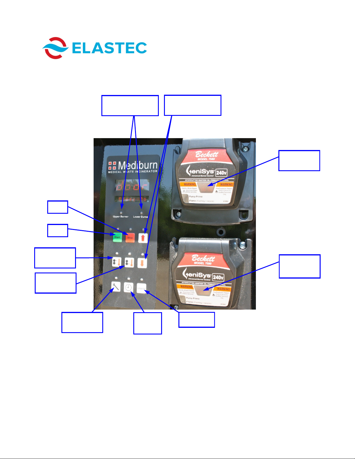
CONTROL PANEL
Maintenance
Information
Burn
Time
Upper
Temperature
Indicator light is red
when burner is on.
Lower Burner
Reset Button
Lower
Temperature
Start
Language
Upper Burner
Reset Button
Stop
Burn time
adjustment

MEDIBURN30 8 D-115 Rev 010
www.elastec.com
HOW IT WORKS
Under-Air
Piping
Under-Air
Blower
MEDIBURN30 9 D-115 Rev 010
www.elastec.com
The operating functions of the burners on the MediBurn30 differ from those of
the original MediBurn in that the 30 has two-stage pumps which oscillate based
on temperature, rising and falling during normal burn operation. As the unit
starts its burn cycle and the temperature climbs, the pumps decrease fuel
usage at specified temperatures. This lowers the heat output of the burners.
However, the temperature continues to rise as the under-fired air in the
primary chamber raises the load temperature by increasing the flame of the
burning material. This process increases temperature to a preset point where
the lower burner can shut off, further reducing fuel usage. The upper burner
also oscillates fuel usage as it works to keep the stack temperature at or above
1000 degrees Celsius.
The MediBurn30 incorporates two 24-volt continuous stall motors. One of
these motors is used to operate and maintain the automatic door lock, which is
activated when the START button is pushed. The other 24-volt motor is used to
open and close the under-fired air bypass.
All of these components are controlled by temperature through the system
controller. Should you as the owner or system user have problems with these
components, please refer to the Troubleshooting Guide found on Pages 19-22
or call Elastec at (618) 382-2525.
HOW IT WORKS
MEDIBURN30 10 D-115 Rev 010
www.elastec.com
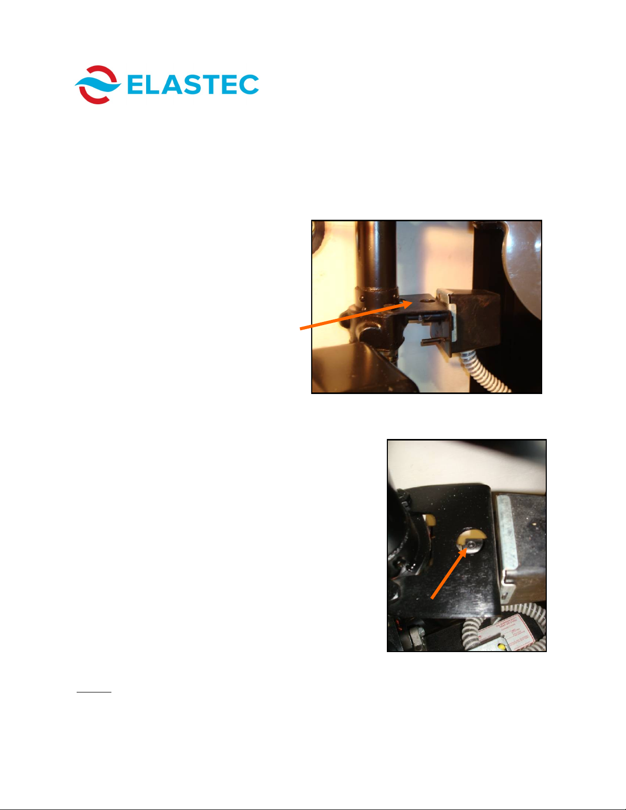
BUTTERFLY ASSEMBLY
The butterfly assembly, located just above the lower burner, is used to open
and close an air bypass. This motor function should be checked on a regular
basis to ensure that it is working properly. In the top of the motor bracket,
there is a small hole that will allow you to view the shaft coupler set screw.
This set screw will turn and disappear out of sight when the motor is activated.
This process can be easily viewed when the lower chamber temperature is
between 600° Celsius and 1000°
Celsius (1112° Fahrenheit and 1832°
Fahrenheit).
The picture to the right shows the set screw
(arrow) as it appears when the MediBurn30 is in
idle. This set screw will rotate out of view when the
temperature climbs above 600° Celsius (1112°
Fahrenheit), indicating the butterfly valve has
opened, allowing air to bypass into the under-air
system. When the lower chamber temperature
reaches 1000° Celsius (1832° Fahrenheit), the
butterfly valve will close and the set screw will
again be visible. It can also be felt by using your
finger. This bracket rarely gets very hot, due to the
cold air that passes through the tubing and
butterfly valve, making it possible to check this by
hand as well as sight. Should you have to replace
this motor, be sure to orient the set screw so that it
can be viewed through the view hole.
NOTE: It is important to maintain this motor in good working condition, as it is
instrumental in the process of fuel savings.

MEDIBURN30 11 D-115 Rev 010
www.elastec.com
DOOR LOCK MOTOR ASSEMBLY
The door lock motor assembly is located on the right side of the burner
compartment. It is designed to lock the burn chamber door as soon as the
START button is pushed. The door-locking system is designed as a safety
feature and is built in such a way that, if tampered with, the MediBurn30 will not
start. When the burn chamber door is open, the controller scrolls “door open,”
and if the burn chamber door is opened during the burn cycle, the unit will
automatically cycle into cool mode and the unit will have to cool to 300C before
restart can begin.
NOTE: The MediBurn30 must always be cooler than 300° Celsius (572°
Fahrenheit) before trying to load unit.
MEDIBURN30 12 D-115 Rev 010
www.elastec.com
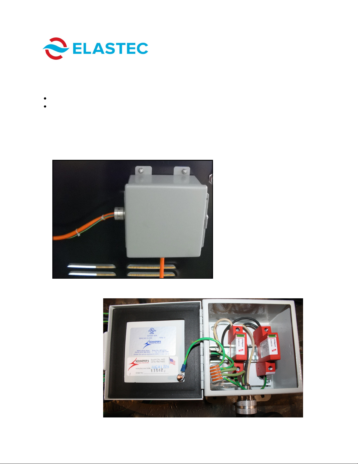
SURGE PROTECTOR ASSEMBLY
This unit is supplied with a surge protector assembly.
This assembly consists of the following:
(1) NEMA 12 steel enclosure
(2) Dehn DG 275 surge arrestors
In the event of a sudden surge in voltage, the surge arrestors will drain the
surge to ground and protect the unit.

MEDIBURN30 13 D-115 Rev 010
www.elastec.com
BURNABLES
MATERIAL RECOMMENDATIONS
Fabrics
Gauze, Garments, Bandages, Swabs
Plastics
Trash Bags, Containers, IV Bags, Tubes, Specimen Cups
WARNING: Each load should contain no more than 25%
plastics. Burning more than the recommended
percentage of plastic causes damage to vital control
components, leading to costly repairs.
Paper
Disposable Gowns, Sheets, Pre-moistened Towels, Paper
Towels
Pathological Waste
Body Parts, Tissue
Waste Chemicals
and Drugs
Medical waste does not include any chemicals or drugs
identified as hazardous waste. Drugs and chemicals
identified as hazardous waste should not be included.
Sharps
Needles and scalpels should not be included with materials to
be put in the unit because of danger in handling. If included,
the sharps would be sterilized but will not melt.
ATTENTION:
Before operating this unit, remove all items and packing material
from the lower burn chamber. There will be some additional packing
material in the upper burn chamber. It is not necessary to remove
packing material from the upper chamber.
Run the unit with the lower burn chamber empty for a 30-minute
cycle. The MediBurn will release smoke and some particulate for a
few minutes during this initial burn.
MEDIBURN30 14 D-115 Rev 010
www.elastec.com
SAFETY INSTRUCTIONS
Before using medical waste incinerator, basic safety precautions should
always be followed to reduce the risk of fire, electric shock and personal injury.
1. Read and understand the instructions in this manual.
2. Follow all warnings and instructions marked on the product.
3. The unit must be disconnected from the power source when there is a
chance water may come into contact with the electrical connections.
4. The unit must be on stable ground and in no danger of falling or tipping.
5. The unit must stand free and clear of surrounding buildings, vegetation or
other combustible material.
6. Ensure that there are no flammable items above the exhaust stack.
7. Never touch the surfaces of the unit while in operation or during the
cool-down period.
8. Do not use the unit in the vicinity of flammable gases.
9. Never put aerosol or other pressurized cans into the unit.
10. If unsure about the safety of disposing of certain items in the unit, consult
your local distributor for details and instructions.
11. Refer servicing to qualified personnel under the following conditions:
Power supply cord is frayed or damaged.
Liquid has been in contact with the electrical system.
The product has been damaged and exhibits a distinct change in
performance.
Fuel is leaking inside the burners.
MEDIBURN30 15 D-115 Rev 010
www.elastec.com
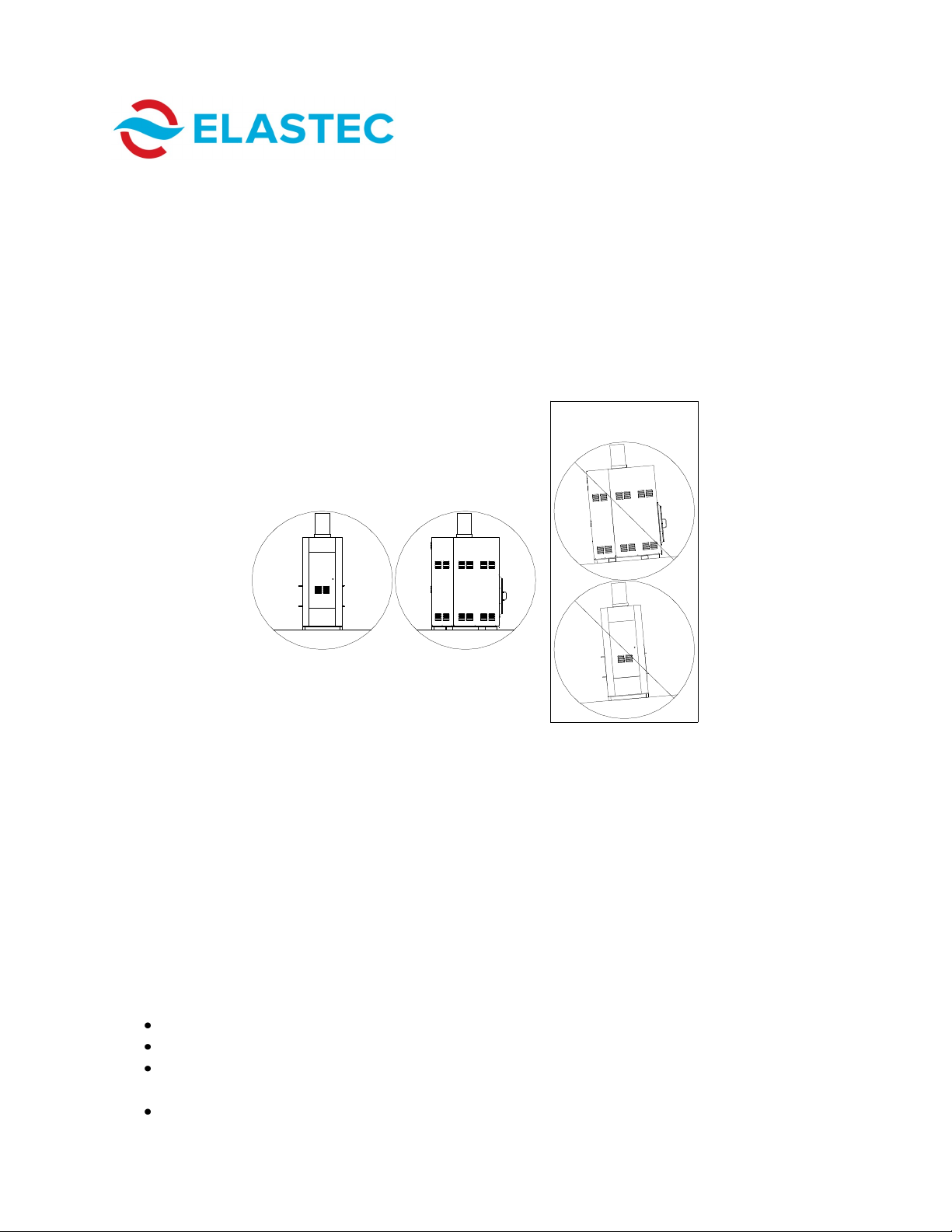
1. Position unit on a level surface at least 2 meters (7 feet) away from existing
structures. Please ensure that there are no overhangs from the building or
overhead wires above the exhaust stack.
2. Connect the electrical plug extending from the control panel of the unit to an
appropriate extension cord. Cord should be no lighter than 12 gauge at 7.5
meters/25 feet. If a longer cord is needed, a heavier gauge wire is required.
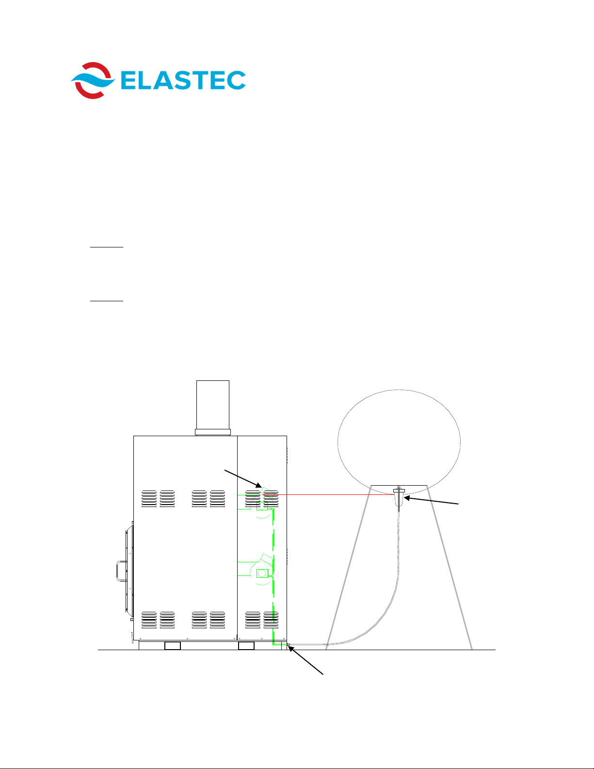
3. If you chose the gravity-fed option (see “Hook-Up,” Page 6), connect the fuel
supply to the burners on the unit with the quick-connect couplings provided.
NOTE: You may be required to bleed air from the fuel system before the first
burn. Refer to the burner parts list for instructions. See below for
connecting a gravity fuel supply system. The fuel tank should be mounted
so that the bottom of the fuel tank is higher than the secondary burner.
NOTE: If the unit has an on-board fuel tank, the gravity fuel supply system
will not be needed.
4. Check door gasket before each use.
Quick-Connect for Optional
Gravity Fuel System
Minimum
Height
Gravity Fuel Supply
System
Fuel Filter
Mounted Tank
(If Applicable)
Secondary
Burner
PREPARING FOR DISPOSAL
MEDIBURN30 16 D-115 Rev 010
www.elastec.com
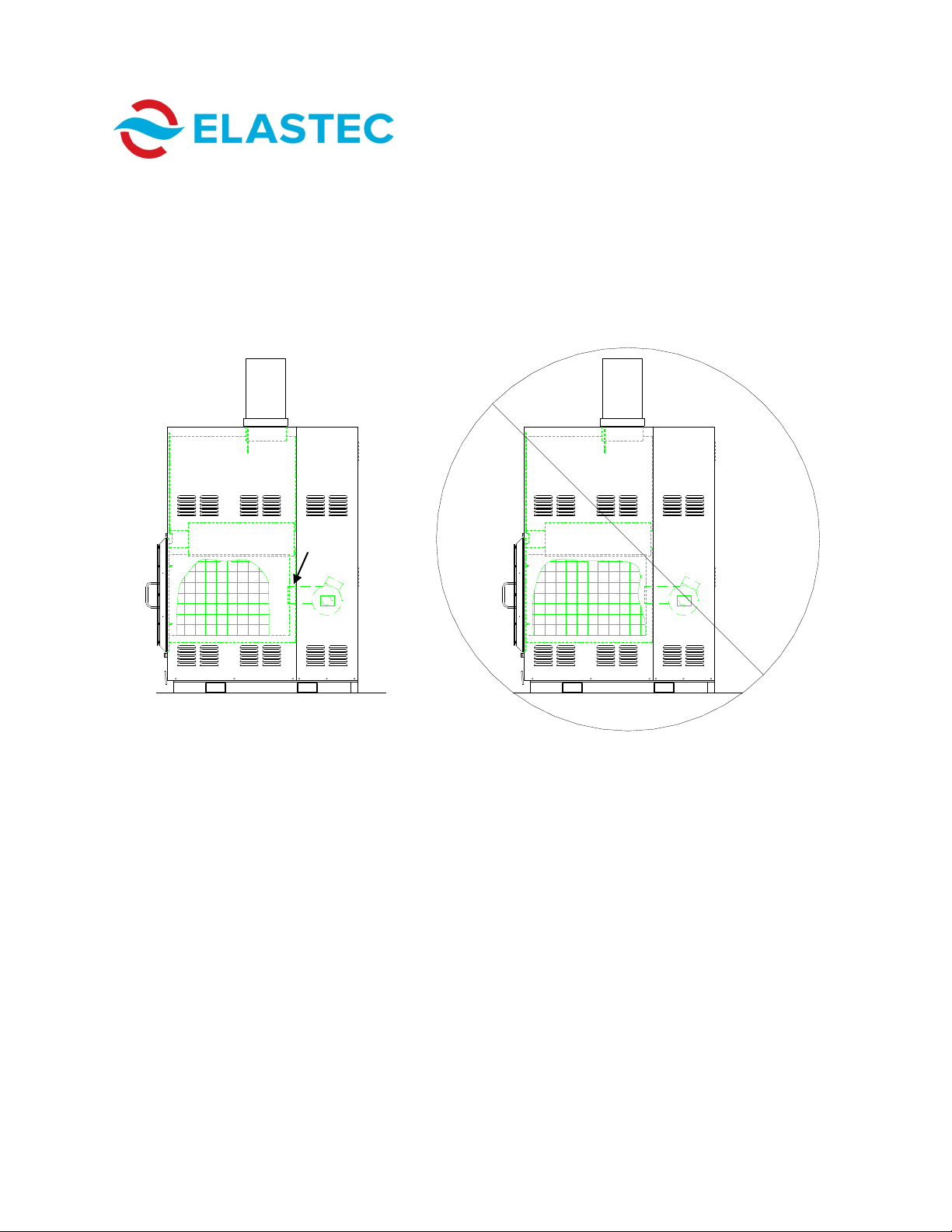
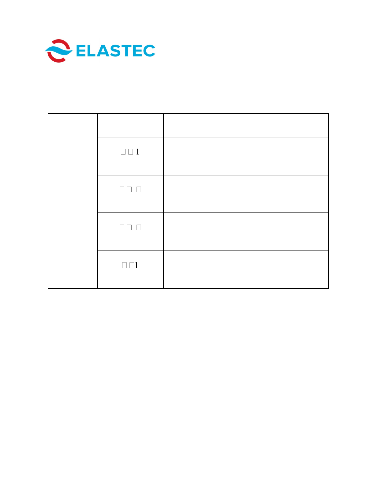
5. Load medical waste material into primary chamber. See below for
recommended loading procedure.
CORRECT
In Figure 1, waste has been loaded
correctly. The operator must allow a 6
inch/15 cm space between burner head
and medical waste.
In Figure 2, waste has been loaded
incorrectly. It is too close to the burner
head.
INCORRECT
Figure 1 Figure 2
6. Securely close door.
7. Choose appropriate cycle time on control panel. See Page 7 for control
panel identification.
8. Push START button to begin cycle.
9. Controller will read IDLE once cycle is complete.
Burner
Head
PREPARING FOR DISPOSAL

MEDIBURN30 17 D-115 Rev 010
www.elastec.com
Once the cycle is complete and the cool-down phase has taken place, the door
lock will disengage. The unit can then be loaded for another cycle. At this
time, the unit is still hot. Care should be taken to avoid touching the surfaces of
the burn chambers. Gloves should be worn at all times.
If refuse from a previous cycle remains in the primary chamber, additional
medical waste may be added to the remains.
If the operator has chosen a cycle that is too short to completely destroy the
load, simply restart the unit. It is not necessary to add more waste.
Before moving the unit, at least a 30-minute cool-down time should be allowed.
For best results, the manufacturer recommends that ash be removed while the
unit is cool and before the incineration of more waste.
CYCLE COMPLETION
ASH REMOVAL
Ash should be removed before the first burn of the day when the unit is cool,
rather than at the end of the day when the unit is hot.
The supplied rake can be used for removing ash from inside the lower
chamber.
MEDIBURN30 18 D-115 Rev 010
www.elastec.com
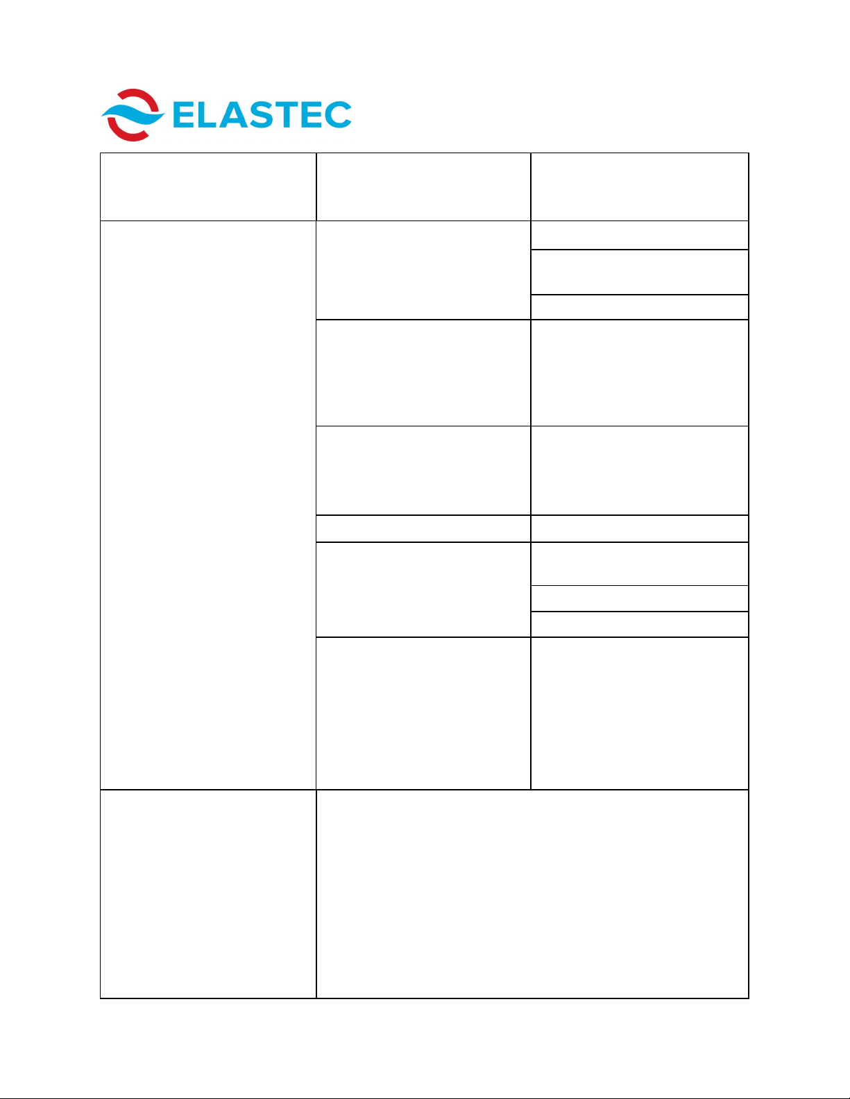
ERROR CODES
DISPLAY
(Example) CONDITION
DISPLAY
Upper In
Sensor failure on Input 1. (Temperature too
high)
Lower In
Sensor failure on Input 2. (Temperature too
high)
Ambient Sensor
Ambient-temperature surrounding the controller
is too high or too low.
Defaults
Controller EEPROM initialization (first time use).
(Restart)
When an error is active and able to be displayed, the control will replace the
normal display with the appropriate error text.

MEDIBURN30 19 D-115 Rev 010
www.elastec.com
TROUBLESHOOTING GUIDE
PROBLEM CAUSE SOLUTION
Fans do not start, burners do not
light and smoke is coming from
the air intake on the burners.
Press the BURNER RESET button, which is located on the burner. It
cannot be seen by the operator but can be reached by placing the
fingers on the round motor housing on the burner. It is unlikely that
this will be a problem, but if it occurs, other burner damage may
result. Please check with the manufacturer if burners continue to
malfunction after the BURNER RESET button is pushed.
Burner ignites but shuts down
after short period Fuel supply is low. Add fuel.
Supply hose is kinked and/or
obstructed. Eliminate kink or obstruction.
Fuel filter is clogged. Replace filter
Cad cell is faulty or not reading
flame.
Cad cell may need to be cleaned.
Wipe clean the eye of the cad
cell. If this does not solve the
problem, replace the cad cell.
Refer to the burner parts list for
location of the cad cell.
Excess material near loading
door not burned
Burn time not long enough Increase burn time.
Not enough air flow through
lower burner
Increase air flow through lower
burner in small increments until
problem ceases.
Upper chamber not burning at
1000° Celsius
Too much air through upper
chamber burner
Close air shutter on burner in
small increments until problem
ceases.
Not enough burn material in load
chamber
Verify load chamber is burning
properly and lower burner is
functioning properly.
Lower burner not functioning
properly
Unit using an excessive amount
of fuel
Air shutters on burners not
adjusted properly
Lower: Look through rear of
burner while adjusting air and set
at brightest point. Adjust air until
smoke is gone from smoke stack.
Fuel bypass solenoids are bad Check solenoid for damage.
Replace if needed.
The under-air fan or blower is not
functioning correctly.
Check to see whether it is work-
ing correctly. If not, check fuses
and replace any blown fuses. If
this does not solve problem, the
motor may need to be replaced.
The next four pages summarize some of the problems that may arise with
your MediBurn unit, as well as the potential causes and some solutions:
MEDIBURN30 20 D-115 Rev 010
www.elastec.com
PROBLEM CAUSE SOLUTION
Burner will not ignite. No spark Check/adjust electrodes.
Ensure that there is power to the
power supply.
Check and clean cad cell.
Too much air Check/adjust air flow. (Factory set
numbers: Top burner bulk air
band is set at 1 and air shutter is
set at 4. Lower burner bulk air
band is set at 1 and air shutter is
set at 3.])
There is air in the fuel supply
system.
Push RESET button on burn
control. Ensure that all fuel line
connections are tight. Air should
purge after repeating this step
two or three times.
Fuel pump coupler is damaged. Replace coupler.
Fuel pump is bad. Low pressure. Check fuel pressure (see setting
for fuel pressure on Page 23).
Set fuel pressure.
Replace pump.
Possible air lock on fuel line. If fuel lines are tight and there is
plenty of fuel; and if the fuel filter
is good and still no fuel, unscrew
filter cap. Fill up halfway with fuel.
Carefully screw cap back and
restart cycle. You may have to do
this two or three times to help
purge and prime pump if system
is airlocked.
Dark smoke is emitted from the
unit.
Adjust airflow to upper burner. The airflow can be adjusted by
rotating the air inflow bracket on the side of the motor. The air flow
adjustments are factory-set but may need to change, depending on
the type of material you are burning. [Factory set numbers: Top
burner bulk air band is set at 1 and air shutter is set at 4. Lower
burner bulk air band is set at 1 and air shutter is set at 3.]To
eliminate smoke, increase the amount of air supplied to the top
burner and decrease the amount of air to the lower burner until the
optimum setting is reached. As the bracket is rotated, larger
numbers on the scale indicate more air intake; lower numbers on the
scale indicate less air intake. For normal operation, the operator will
learn which setting for air intake best suits the typical load.
TROUBLESHOOTING GUIDE
Table of contents


