Advantech POC127 User manual

POC127
Point of Care Terminal with Intel®
Pineview-M N450 CPU and 12.1” VA LCD
(Computer)
The Instructions for the User
The document combines text and illustrations, providing a comprehensive overview of the
system. The information is presented as sequential steps of action, allowing the user to
learn directly how to use the device.
The text provides explanations and instructs the user step by- step in the practical use of the
product, with short, clear instructions in easy-to-follow sequence.
Definitions
Warning! A WARNING statement provides important information
about a poten-tially hazardous situation which, if not
avoided, could result in death or serious injury.
Caution! A CAUTION statement provides important information about
a poten-tially hazardous situation which, if not avoided, may
result in minor or moderate injury to the user or patient or in
damage to the equipment or other property.
Note! A NOTE provides additional information intended to avoid
inconve-niences during operation.
Safety Instructions
1. Strictly follow these Instructions for Use; please read these safety
instructions carefully.
2. Please keep this User Manual for later reference; any use of the
product requires full understanding and strict observation of all
portions of these instruc-tions. Observe all WARNINGS and
CAUTIONS as rendered throughout this manual and on labels on the
equipment.
3. Repair of the device may only be carried out by trained service
personnel. Advantech recommends that a service contract be
obtained with Advantech Service and that all repairs also be carried
out by them. Otherwise the correct functioning of the device may be
compromised.
Warning! Because of the danger of electric shock, never remove the
cover of a device while it is in operation or connected to a
power outlet.
4. If one of the following situations arises, have the equipment checked by
service personnel:
The power cord or plug isdmaged.
Liquid has penetrated into the equipment.
The equipment has been exposed to
moisture.
The equipment does not work well, or you cannot get it to work according
to the user manual.
The equipment has been dropped and damaged.
The equipment has obvious signs of breakage.

5. Disconnect this equipment from any AC outlet before cleaning. Use a damp
cloth. Do not use liquid or spray detergents for cleaning and keep this
equip-ment away from humidity.
Caution! To avoid short-circuiting and otherwise damaging the device, do not
allow fluids to come in contact with the device. If fluids are accidentally
spilled on the equipment, remove the affected unit from service as
soon as possible and contact the service personnel to verify that
patient safety is not compromised.
6. Put this equipment on a reliable surface during installation. Dropping it or
letting it fall may cause damage. For plug-in equipment, the power outlet
socket must be located near the equipment and must be easily accessible.
Caution! To prevent overheating, do not cover the openings or place the device
in direct sunlight or near radiant heaters.
7. Make sure the voltage of the power source is correct before connecting the
equipment to the power outlet. Position the power cord so that people cannot
step on it. Do not place anything over the power cord. If the equipment is not
used for a long time, disconnect it from the power source to avoid damage by
transient over voltage.
Caution! Do not leave this equipment in an uncontrolled environment where the
storage temperature is below -20° C (-4° F) or above 60° C (140° F).
This may damage the equipment.
8. If your computer does not keep the correct time or the BIOS configuration
has been reset to default, the battery may have no charge.
Caution! Do not replace battery yourself. Please contact a qualified technician or
your retailer.
The computer is provided with a battery- powered, real-time clock circuit.
There is a danger of explosion if battery is incorrectly replaced. Replace
only with same or equivalent type recommended by the manufacturer.
Discard used batteries according to the manufacturer’s instructions.
Caution! The battery charging indicator is not included with this device. It will be
added to the finished system assembly and be shown with the com-
pleted system.
9. Improper installation of VESA mounting can result in serious personal injury!
VESA mount installation should be operated by professional technician, please
contact the service technician or your retailer if you need this service. The
detail operating procedure is specified in Appendix A.
10. Classification:
1). Supply Class I s
2). No applied part
3). Continuous Operation
4). Not AP or APG category
Warning! This device is not suitable for use in the presence of flammable anes-thetic
mixture with air, oxygen, nitrous oxide, or for life support systems.

11. Environmental protection: follow national requirements to dispose of unit.
12. Maintenance: to properly maintain and clean the surfaces, use only
the approved products or clean with a dry applicator.
Caution! When servicing the device, always use replacement parts that are quali-
fied to Advantech standards. Advantech Digital Healthcare cannot war-
rant or endorse the safe performance of third-party replacement parts
for use with our medical device.
13. Make sure the user does not allow contact between SIP/SOPs and the
patient at the same time.
14. When networking with electrical devices, the operator is responsible for
ensuring that the resulting system meets the requirements set forth by the
following standards:
– EN 60601-1 (IEC 60601-1)
Medical electrical equipment
Part 1: General requirements for safety
– EN 60601-1-1 (IEC 60601-1-1)
Medical electrical equipment
Part 1-1: General requirements for safety
Collateral standard: Safety requirements for Medical electrical systems
– EN 60601-1-2 (IEC 60601-1-2)
Medical electrical equipment
Part 1-2: General requirements for safety
Collateral standard: Electromagnetic compatibility; Requirements and tests
15. Accessory equipment connected to analog and digital interfaces must be in
compliance with the respective nationally harmonized IEC standards (i.e. IEC
60950 for data processing equipment, IEC 60065 for video equipment, IEC
61010-1 for laboratory equipment, and IEC 60601-1 for medical equipment.)
Furthermore all configurations shall comply with the system standard IEC
60601-1- 1. Anyone who connects additional equipment to the signal input part
or signal output part is configuring a medical system, and is therefore, responsi
- ble that the system complies with the requirements of the system standard
IEC 60601-1-1. The unit is for exclusive interconnection with IEC 60601-1
certified equipment in the patient environment and IEC 60XXX certified
equipment out-side of the patient environment. If in doubt, consult the technical
services department or your local representative.
Caution! Use suitable mounting apparatus to avoid risk of injury.
16. Grounding reliability can only be achieved when the equipment is connected
to an equivalent receptacle marked "Hospital Only" or "Hospital Grade".
17. Use a power cord that matches the voltage of the power outlet, which has been
approved and complies with the safety standard of your particular country.
Note! Environmental protection
Follow national requirements to dispose of unit.
18.“WARNING‐Donotmodifythisequipmentwithoutauthorizationofthe
manufacturer.”
19.“WARNING–Toavoidriskofelectricshock,thisequipmentmustonlybe
connectedtoasupplymainswithprotectiveearth.
20.“CAUTION:ThisadapterSinproPower:Type:HPU101‐107W/PFCisaforming
partofthemedicaldevice”.
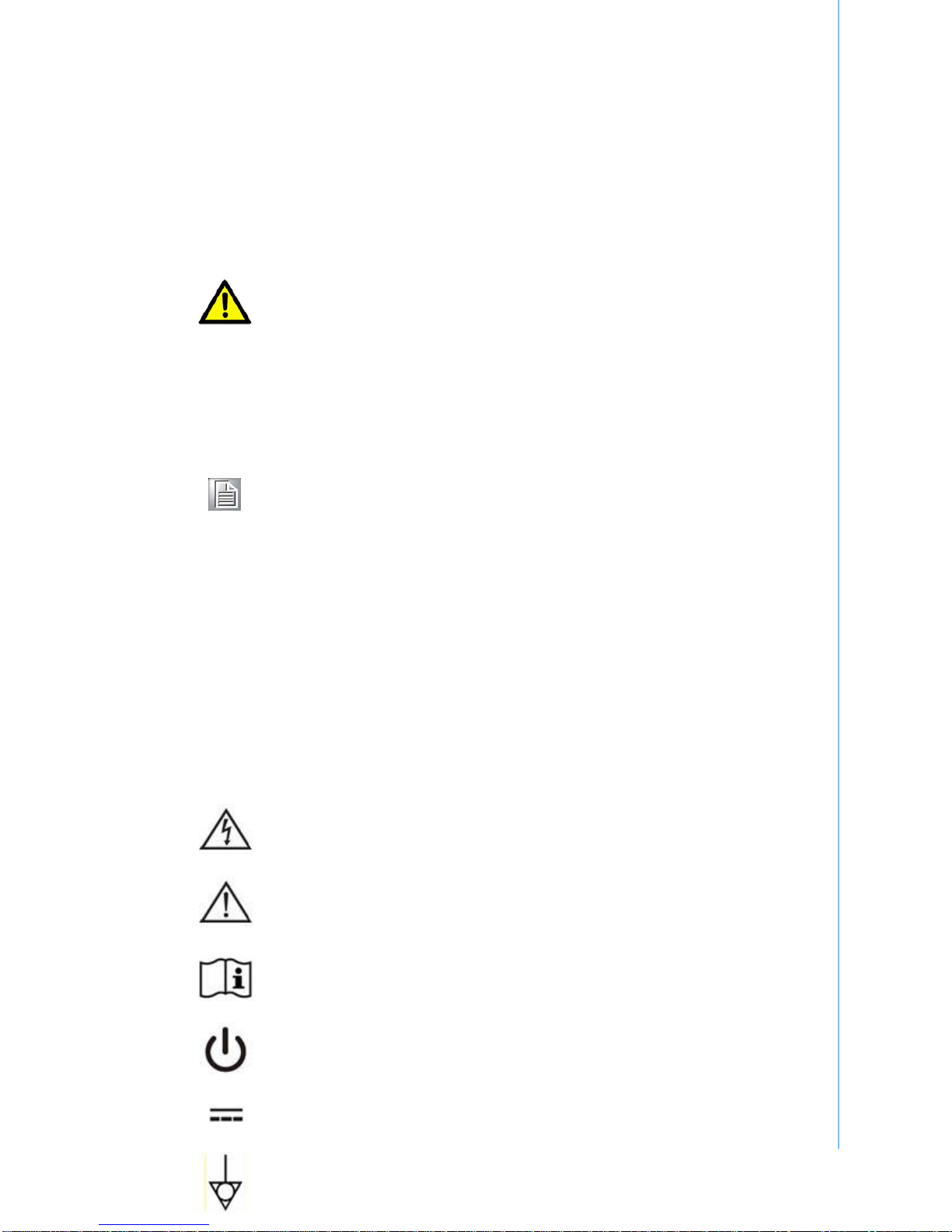
Explanation of Graphical Symbols
IEC 60878 and ISO 3864-B.3.6 : Warning: dangerous voltage
ISO 7000-0434 : Caution, consult ACCOMPANYING DOCUMENTS.
ISO 7000-1641 : Follow operating instructions or consult instructions for
use.
IEC 60417 -5009 : STAND-BY.
IEC 60417-5031 : Direct current.
IEC 60417-5021 : Equipotentiality.

Disposing of Old Products
Within the European Union
EU-wide legislation, as implemented in each member
state, requires that waste electrical and electronic
products carrying the mark shown at left must be
disposed of separately from normal household waste.
This includes monitors and electrical accessories, such as
signal cables or power cords. When you need to dis-pose
of your display products, please follow the guidance of
your local authority, or ask the shop where you purchased
the product, or if applicable, follow any agreements made
between you and the provider.
The mark on electrical and electronic products only
applies to the current European Union Member States.
FCC Class B
This equipment has been tested and found to comply with the limits for a
Class B digital device, pursuant to Part 15 of the FCC Rules.
These limits are designed to provide reasonable protection against harmful
interference when the equipment is operated in a residential environment.
This equipment generates, uses and can radiate radio frequency energy. If
not installed and used in accordance with this user manual, it may cause
harmful interference to radio communications.
Note that even when this equipment is installed and used in accordance
with this user manual, there is still no guarantee that interference will not
occur. If this equipment is believed to be causing harmful interference to
radio or television reception, this can be determined by turning the
equipment on and off. If interference is occur-ring, the user is encouraged
to try to correct the interference by one or more of the following measures:
Reorient or relocate the receiving antenna
Increase the separation between the equipment and the receiver
Connect the equipment to a power outlet on a circuit different from
that to which the receiver is connected
Consult the dealer or an experienced radio/TV technician for help
Warning! Any changes or modifications made to the equipment which
are not expressly approved by the relevant standard’s
authority could void your authority to operate the equipment.
FCC Caution: Any changes or modifications not expressly approved by the party
responsible for compliance could void the user's authority to operate this equipment.
FCC RF Radiation Exposure Statement:
1. This Transmitter must not be co-located or operating in conjunction with any
other antenna or transmitter.
2. This equipment complies with FCC RF radiation exposure limits set forth for an
uncontrolled environment. This equipment should be installed and operated with
a minimum distance of 20 centimeters between the radiator and your body.

List of Accessories
Before installing your Point-of-Care Terminal, ensure that the following
materials have been received:
POC127 series Point-of-Care Terminal
Accessories for POC127
CD-ROM disc-"Drivers, User's manual and Utilities"
Mounting kits and packet of screws.
VESA mounting note x1
China RoHS notex1
Warning! No user serviceable parts inside; refer servicing to qualified
personnel. Only the accessories indicated on the list of
accessories above have been tested and approved to be used
with the device. Accordingly it is strongly recommended that
only these accessories be used in conjunc-tion with the
specific device. Otherwise the correct functioning of the device
may be compromised.
Additional Information and Assistance
Contact your distributor, sales representative, or Advantech's customer service center for
technical support if you need additional assistance. Please have the following information
ready before you call:
Product name and serial number
Description of your peripheral attachments
Description of your software (operating system, version, application software, etc.)
A complete description of the problem
The exact wording of any error messages
This equipment is a source of electromagnetic waves. Before use please, make sure
that there are not EMI sensitive devices in its surrounding which may malfunction
therefore.
Environmental protection
Follow national requirements to dispose of unit.
Manufacturer:
Advantech Co., Ltd.
No.1, Alley 20, Lane 26, Rueiguang Road Neihu District, Taipei,
Taiwan 114, R.O.C.
TEL: (02) 2792-7818
Distributed in Europe by:
Advantech Europe GmbH Kolberger Straße 7
D-40599 Düsseldorf, Germany
Tel: 49-211-97477350
Fax: 49-211-97477300
Visit the Advantech websites at www.advantech.com or
www.advantech.com.tw if you need more information.

Visit the Advantech websites at www.advantech.com or www.advantech.com.tw if you
need more information.

Chapter 1 General Information
1.1 Introduction
The POC127 is a Intel® Atom™ Processor Processor N450 1.66G Hz mobile processor-
based computer that is designed to serve as a Point of Care terminal (POC.) It is a PC-based
system with 12.1” color TFT LCD display, Single DVI-I Port, Dual on-board 10/100/1000 PCI-
E Ethernet controller, Quad COM ports, Quad USB 2.0 ports and a 24-bit stereo audio
controller.The POC127 is an user-friendly computer. For system integrators, this highly
integrated multimedia system lets you easily build a Point of Care Terminal into your
applications. The POC127 makes it an ideal and safe point of care solution for patients and
hospital practitioners.
The POC127 is specially designed to resist spills and water damage, and ensures dust
resistance with its protected LCD, sealed ports, like a complete system. The high contrast
ratio (1500:1) of POC127 makes it a perfect image terminal for PACS and DICOM
applications. The POC127 is a reliable solution to your application's processing requirements.
Intended use - The POC127 is intended to serve as a Point of Care terminal (POC)
for integration with hospital system. POC127 medical computing is designed for
general purpose for hospital environment. For data collection and display for reference.
It shall not be used for life-supporting system.
The latest version of user's manual is available to be downloaded from
http://support.advantech.com.tw/support/

1.2 Specifications
Chipset Intel Pineview-M; Intel ICH8M
CPU Intel® Atom™ Processor Processor
N450 1.66G Hz
Front Side Bus 667 MHz
Computing System
Memory Up to 2GB DDR2 667 MHz SDRAM
Graphics Controller INTEL Pineview-M with Extreme
Graphic technology
System input rating Input Voltage +18 VDC,3.5 A.
DC Model AC/DC adapter (Sinpro Model
no.HPU101-107)
Input Voltage 100-240V AC, 47-63Hz, 1.2-0.5A
Power Supply
Output Voltage +18 VDC,5.55 A.
Mini PCIe 1 x mini PCIe
Expansion Slot PCIe /PCI 1 x PCIe x4 slot or PCI x1 (by riser
card option)
Storage CF 32GB CF card
Identification 1x Smart Card Reader (option)
Speakers 2 x 2 W speakers;
Display size 12.1 inch
Display Mode TN, Normally black
Max. Resolution 800 x 600
Max. Colors 262k/16.2M colors
Dot size (mm) 0.3075 x 0.3075
Viewing angle 160/140
Luminance 600 cd/m2
Backlight LED
Display
Contrast ratio 1500:01:00
WLAN IEEE 802.11 a/b/g/n
Optional Function DOM 1-8GB disk on module kit
Type Analog Resistive
Touch screen
Resolution Continuous

Light transmission 75%
Controller RS-232 interface (use COM 6)
Durability 30 million touches
CE,FCC Class B approved/ RF
Certification Controller UL60601-1,EN60601-1 approved
Temperature 0 ~ 40°C (32 ~ 104°F) (Operating)
-20 ~60°C (Storage)
-20 ~60°C (Transportation)
Humidity 10 ~ 90% @ 40°C (non-condensing)
5 ~90% (non condensing) (Storage)
5 ~90% (Transportation)
Pressure 700-1013 hPa (Operation)
375 mmHg to 760 mmHg (Storage)
375mmHg to 760 mmHg (Transportation)
Environment
Shock Resistance 20G peak acceleration (11ms duration)
Water/dust Resistance IPX1 compliant
Dimensions (W x H x
D) 348 x 287 x 92 mm (13.70" x 11.29" x
3.62")
Physical Characteristics
Weight 4.5 kg
Platform & utility XP Professional, Windows 7, SUSI

Figure 1-1: Dimension
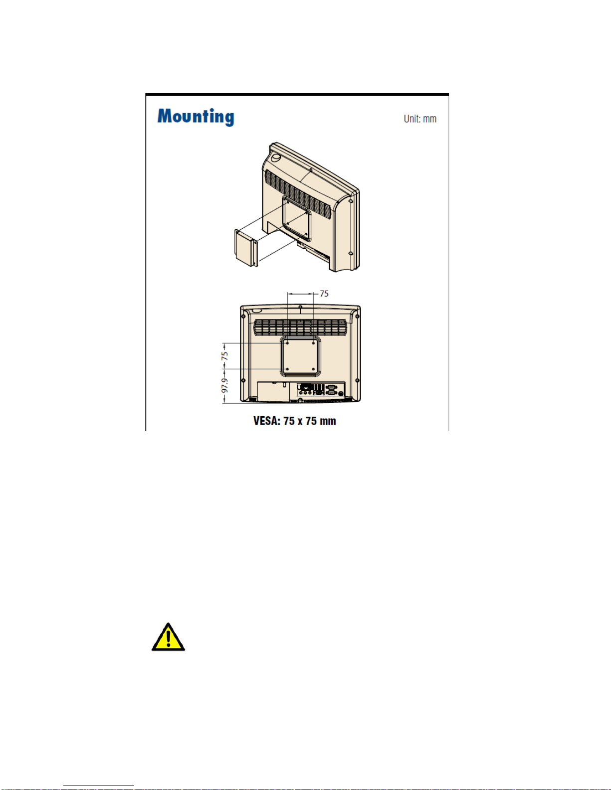
VESA Mounting: 75x75mm
Figure 1-2: VESA Mounting
PleaseuseM4x12L(Maxium)screwx4
Cleaning and Disinfecting
During normal use of the POC (Point-of-Care Terminal) the device may become
dirty
and should be regularly cleaned.
Steps:
1. Prepare cleaning water
2. Wipe the POC with a clean cloth that has been moistened in the pure water.
3. Wipe thoroughly with a clean cloth.
Caution!
○ Do not immerse or rinse the POC or its peripherals. If you accidentally
spill liquid on the device, disconnect the unit from the power
source. Contact your IT support department regarding the continued
safety of the unit before placing it back in operation-Do not
spray cleaning agent on the chassis.
○ Do not use disinfectants that contain phenol.
○ Do not autoclave or clean the POC or its peripherals with strong
aromatic, chlorinated, ketone, either, or ether solvents, sharp tools

or abrasives. Never immerse electrical connectors in water or other
liquids.
Chapter 2 System Setup
2.1 A Quick Tour of the POC127
Before you start to set up the POC127, take a moment to become familiar with the locations
and purposes of the controls, drives, connections and ports, which are illustrated in the
figures below.
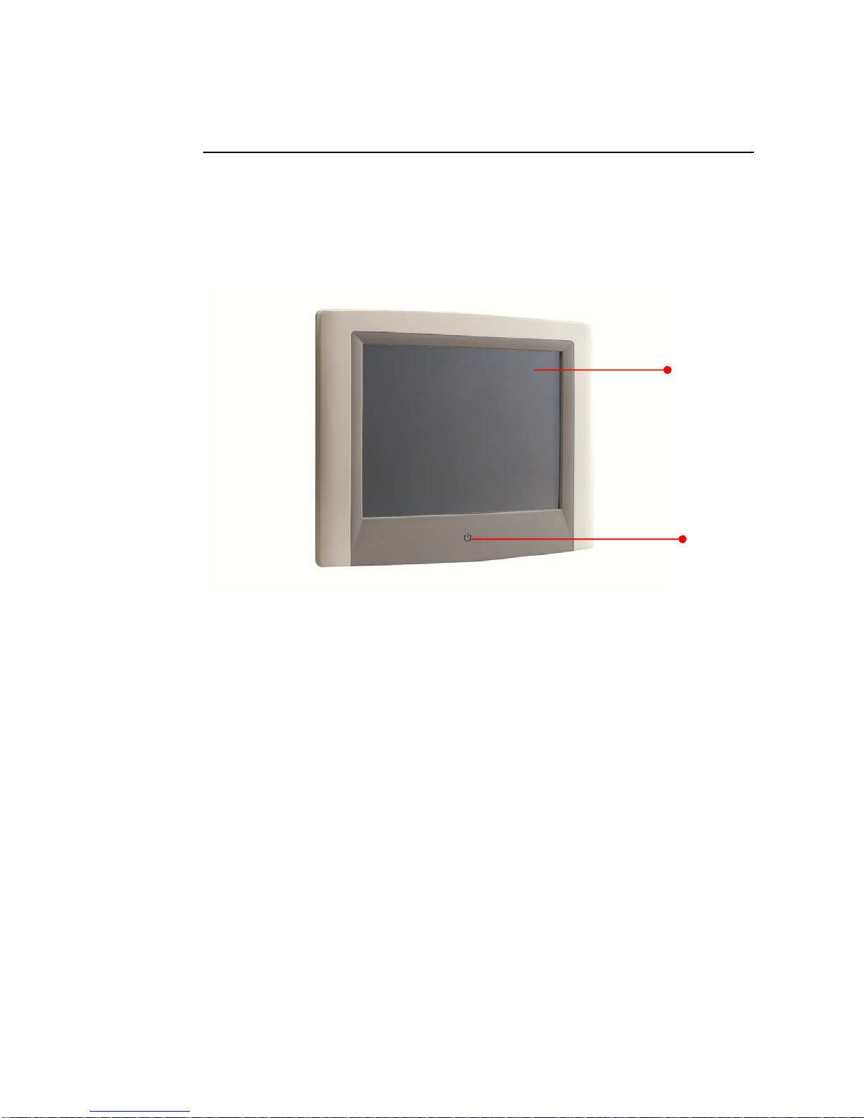
When you place the POC127 upright on the desktop, its front panel appears as shown in
Figure 2-1.
2.1.1 Front View
Figure 2-1: Front View of the Point of Care Terminal
2-1 Front Bezel view
(1) LCD panel with Touch Screen option
(2) Power symbol w/ indicator light
(1)
(2)
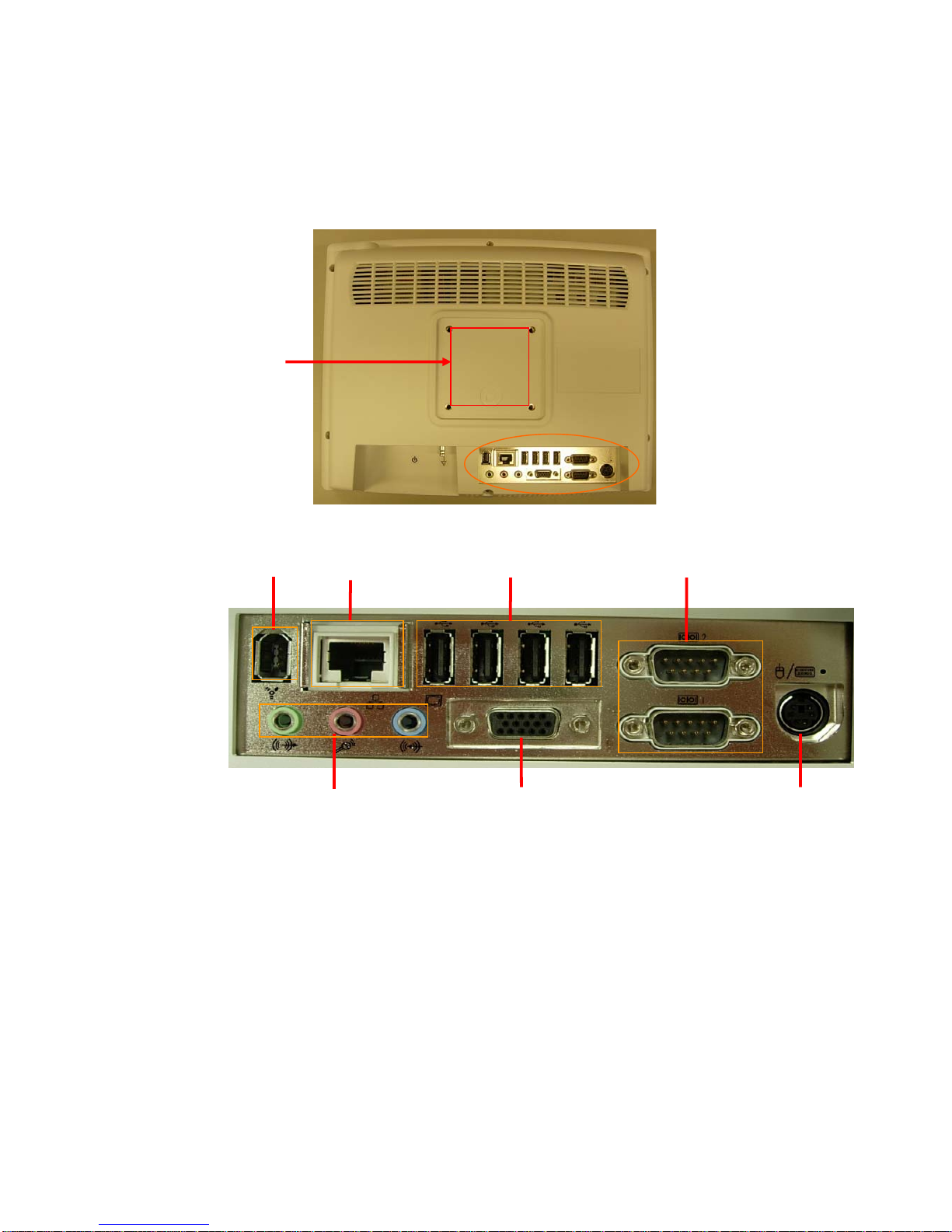
2.1.2 Rear View
When you turn the Point of Care Terminal around and look at its rear cover, the sunken I/O
section is at the bottom of the panel PC, as shown in Figure 2-2 and zoom in Figure 2-3.
(The I/O section includes various I/O ports, including serial ports, VGA port, the Ethernet port,
USB ports and so on.)
Figure 2-2: Rear view of the Point of Care Terminal
Figure 2-3: Rear view of Multi I/O ports
2-2 and 2-3 Rear view
(1) VESA mounting 75mmx75mm
(2) IEEE 1394a port
(3) Ethernet (network) ports labeled TCP/IP (LAN1)
(4) USB1-USB4 ports*
(5) COM1 – COM2 serial ports
(6) Line-out, Microphone-in & Line in jack
(7) VGA port
(8) KB/MOUSE (keyboard/mouse) PS/2 port
(3)
(7)
(4)
(8)
(6)
(5)
(1)
(2)

2.1.3 Bottom view
Figure 2-4: Bottom view
(9) DC-in Jack
(10) Power switch
(11) Equipotential terminal
(12) Add on card bracket
(13) Speaker x2
NOTE:
Equipotential terminal
need link to
hospital ground/earth system before system boot
to protect operator and system
.
(9)
(12)
(11)
(10)
(13)
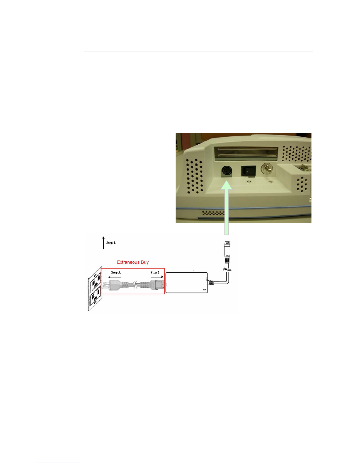
2.2 Installation Procedures
2.2.1 Connecting the Power Cord
The POC127 could only be powered by a DC power adapter (SINPRO Model no.HPU100-
107). Be sure to always handle the power cords by holding the plug ends only.
Follow these procedures in order:
1. Connect the female end of the power adapter to the DC jack of the panel PC. (See Figure
2-7.)
2. Connect the female end of the power cord to the DC power adapter
3. Connect the 3-pin male plug of the power cord to an electrical outlet.
Figure 2-7: Connecting the power cord
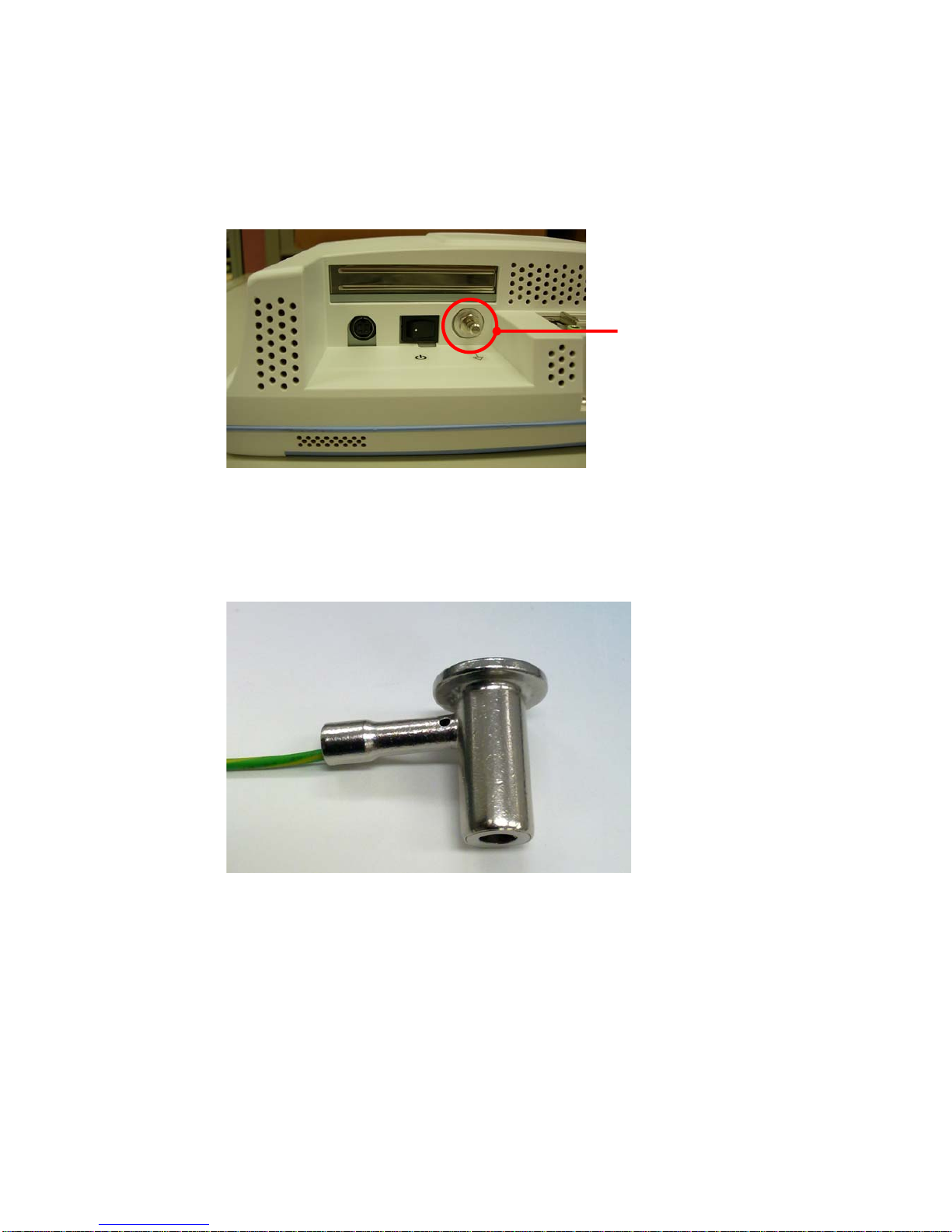
2.2.2 Connecting the Ground Pin
Step 1. System ready and find the Equipotential Terminal on rear side of POC.
An Equipotential Terminal is provide to optionally connect to a hospital ground/earth
system
Figure 2-8: POC127 Equipotential Terminal Pin
Step 2. Prepare the Grounding cable and the other terminal link to hospital ground/earth
system.
Figure 2-9: Grounding cable with connector
Step 3. Grounding cable plug with POC127 Equipotential Terminal (See Figure 2-8)
EquipotentialTerminal
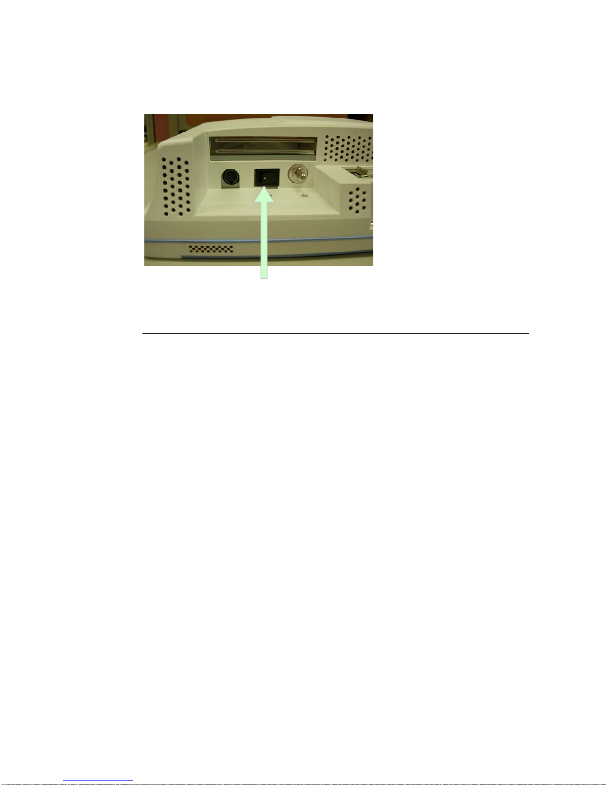
2.2.2 Switch on the power
Switch on the reset switch on the front cover. (See Figure 2-4.)
Figure 2-11: Press the power button to boot system
Other manuals for POC127
1
Table of contents
Other Advantech Medical Equipment manuals


Popular Medical Equipment manuals by other brands


Johnson & Johnson
Johnson & Johnson DePuy Synthes Battery Power Line II Instructions for use

Otto Bock
Otto Bock AxonSoft 2.2 560X500 V2.2 Instructions for use

OAKWORKS
OAKWORKS 300 Series user manual

Mettler Electronics
Mettler Electronics Auto Therm 395 instruction manual

Medisana
Medisana HS 680 instruction manual

Hospira
Hospira Micro Macro plum XL System Operating Manual


