ELBRO TESTER 2550LCD User manual

D
Bedienungsanleitung
F Mode d’emploi
I Istruzioni per l’uso
E Operating Instructions
TESTER 2550LCD
TESTER 2550LCD
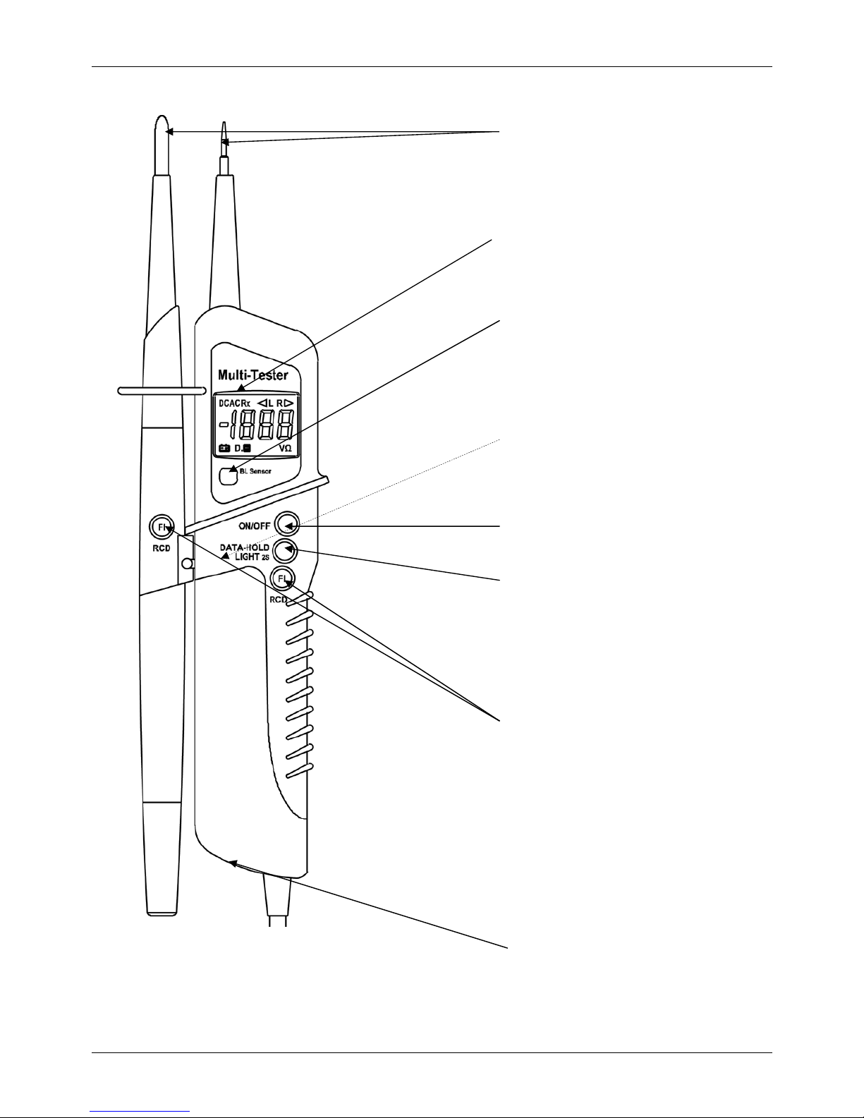
2
LC-Display
Back Light sensor
ON / OFF
D:Prüfspitzen mit 4mm Adapter
F:Pointes de touche avec adaptateurs 4mm
I: Punte di misura con adattatori 4mm
E:Probe tips with 4mm adapters
D:Schraube Batteriefach
F:Vis compartiment de batterie
I: Vite alloggiamento delle batterie
E:Screw battery compartment
D:Fingerkontakt (Rückseite)
F:Contact digital (en arrière)
I :Contatto a dito (posteriore)
E:Finger contact (backside)
Data-Hold / LED
D:Tasten für FI/RCD-Auslösetest
F:Touches pour le test FI/RCD
I :Tasti per la prova dell’interruttore diff.
E:Keys for the FI/RCD trip test

TESTER 2550LCD
3
Bedienungsanleitung
Vielen Dank, dass Sie sich für den TESTER 2550LCD, einen zweipoligen Spannungsprüfer mit LCD-Anzeige,
entschieden haben. Es können Gleich- und Wechselspannungen von 6 bis 1000 V, Polaritäts-, Drehfeldrichtungs-
und Durchgangsprüfungen bis 2 kΩsowie FI/RCD-Tests durchgeführt werden.
Der TESTER 2550LCD ist durch die hohe Schutzart (IP65) auch bei rauem Einsatz verwendbar.
1. Sicherheitshinweise
Sie haben sich für ein Gerät entschieden, das Ihnen ein hohes Maß an Sicherheit bietet. Es entspricht den Normen
DIN VDE 0682-401, IEC/EN 6643-3. Um eine gefahrlose und richtige Anwendung sicherzustellen, ist es
unerlässlich, dass Sie diese Bedienungsanleitung vor dem ersten Gebrauch vollständig durchlesen.
Es gelten folgende Sicherheitsvorkehrungen:
•Der Spannungsprüfer muss kurz vor dem Einsatz auf Funktion übergeprüft werden. Überprüfen Sie das
Gerät an einer bekannten Spannungsquelle, z.B. 230V-Steckdose. Fällt hierbei die Anzeige einer oder
mehrerer Funktionen aus, darf das Gerät nicht mehr verwendet werden und muss von Fachpersonal
überprüft werden.
•Gerät nur an den Handgriffen anfassen, vermeiden Sie die Berührung der Prüfspitzen!
•Prüfungen auf Spannungsfreiheit nur zweipolig durchführen!
•Eine einwandfreie Anzeige ist im Temperaturbereich von –10°C - +50°C sichergestellt.
•Das Gerät immer trocken und sauber halten. Das Gehäuse darf mit einem feuchten Tuch gereinigt
werden.
•Das zusätzlich anzeigende Warnsymbol und akustische Anzeige bei Spannungen >35V dienen nur zur
Warnung von lebensgefährlichen Spannungen, nicht zur Messung
2. Allgemeines
Spannungen haben Priorität. Liegt keine Spannung an den Messspitzen an (< 3,0V), befindet sich das Gerät im
Modus Durchgangsprüfung.
3. Funktion
Um das Gerät ein bzw. auszuschalten betätigen Sie die „ ON/OFF“ Taste. Nach ca. 7 min. schaltet das Gerät
automatisch durch die „ Auto Power Off“ Funktion ab.
Durch längeres drücken der D-H Taste wird die LED Taschenlampe zugeschaltet
4. Selbsttest
Halten Sie zum Test die Prüfspitzen aneinander. Der Prüfsummer muss deutlich ertönen und die Anzeige
„000“ anzeigen. Sollte das LC- Display nicht oder nur schwach aufleuchten, müssen die Batterien erneuert werden.
5. Gleichspannung prüfen
Bei Anlegen der Prüfspitzen an eine Gleichspannung innerhalb des Nennspannungsbereiches wird die Spannung
in Volt angezeigt und zusätzlich erscheint „ DCV“ im Display. Liegt an der Prüfspitze „L1“ eine negative Spannung
an, wird ein „-„ (Minus) vor dem Wert angezeigt.
6. Wechselspannung prüfen
Bei Anlegen der Prüfspitzen an eine Wechselspannung innerhalb des Nennspannungsbereiches wird die
Spannung in Volt angezeigt und zusätzlich erscheint „ ACV“ im Display. Ab einer Spannung von ca. 35V wird die
lebensgefährliche Spannung mittels blinkender LED hinter dem Display angezeigt.
7. Data Hold – Funktion
Durch das Betätigen der „Data- Hold“ –Taste ( Datenspeicher ) kann ein Widerstandsmesswert auf dem LC-Display
gespeichert werden. Die „Data-Hold“-Funktion wird durch die Anzeige „D-H“ auf dem Display Feld angezeigt und
kann durch nochmaliges Betätigen der gleichen Taste wieder ausgeschaltet werden.

TESTER 2550LCD
4
8. Phasenprüfung
Berühren Sie mit einer der Prüfspitzen einen Leiter und berühren Sie dabei den rückseitigen Fingerkontakt. Bei
Anliegen einer Phase, mind. 100V~, erscheint in dem kleinen LC- Display „<L“. Für die Bestimmung der
Phasenleiter durch den Fingerkontakt kann die Wahrnehmbarkeit der Anzeige beeinträchtigt werden, z. B. durch
isolierende Vorrichtungen zum Schutz gegen direktes Berühren, in ungünstigen Positionen, zum Beispiel auf
Holzleitern oder isolierenden Fußbodenbelägen, einer nicht geerdeten Spannung oder auch bei ungünstigen
Lichtverhältnissen.
9. Drehfeldprüfung
Stellen Sie nach Punkt 8 einen phasenführenden Leiter fest. Legen Sie nun zwei Phasenleiter an die Prüfspitzen
an und berühren Sie den Fingerkontakt. Im Display erscheint „<L“ für ein linksdrehendes bzw „R>“ für ein
rechtsdrehendes Feld. Die Spannungsangabe sollte ca. 400V anzeigen. Leuchtet „<L“ im LC-Display und werden
nur ca. 230V angezeigt, liegt nur ein Phasenleiter an!
10. Widerstandsmessung / Durchgangsprüfung
Das zu prüfende Objekt muss spannungsfrei sein.
Legen Sie die Prüfspitzen an die zu prüfende Leitung, Sicherung o.ä. an. Bei einem Widerstand von 0...2 kΩ
erscheint der Widerstandswert auf dem Display und ein akustisches Signal ertönt. Ist der Messwert >2 kΩ, so
erscheint im Display die Überlaufanzeige “1“.
11. FI/RCD-Auslösetest, PE (Nullleitertest)
Der Tester 2550LCD besitzt eine Last, die es ermöglicht, einen FI/RCD-Schutzschalter mittels zweier Taster
(FI/RCD) auszulösen. Geprüft wird der FI/RCD zwischen Phase und Schutzleiter (max. Prüfspannung 240 V)
12. Hintergrundbeleuchtung
Bei Betrieb in lichtschwacher Umgebung schaltet der Back-Light-Sensor automatisch die Hintergrundbeleuchtung
des Displays ein, um ein sicheres Ablesen des Messwertes auch bei völliger Dunkelheit zu ermöglichen.
13. Batteriewechsel
Zum Wechsel der Batterien ist die Schraube unten am Hauptgehäuse zu lösen, um den Batteriefachdeckel nach
unten abziehen zu können. Achten Sie beim Einsatz der neuen Batterien auf die richtige Polarität.
Hinweis: Batterien gehören nicht in den Hausmüll. Auch in Ihrer Nähe befindet sich eine Sammelstelle!
14. Technische Daten
Anzeige: 3½-stelliges, beleuchtetes LC-Display
Nennspannungsbereich: 6...1000V AC/DC
Frequenzbereich: 0...400Hz
Phasenanzeige: > 100 V AC
Prüfstrom: IS <0.3A 7 In <3,5 mA
Einschaltdauer: max. 30s an / 240s aus
Durchgangsprüfung: 0...2kΩ,
0…35 Ωakustisch
Widerstandsmessung: 0...2kΩ
Schutzart: IP65
Überspannungskategorie: CAT IV 1000V
Sicherheit nach: IEC/EN 6643-3
Stromversorgung: 2x 1,5V Typ AAA Micro

TESTER 2550LCD
5
15. Konformitätserklärung
Das Produkt erfüllt die Niederspannungsrichtlinien 73/23/EWG und die EMV-Richtlinien 89/336/EWG.
16. Anwendungsbereich
Das Gerät ist nur für die in der Bedienungsanleitung beschriebenen Anwendungen bestimmt. Eine andere
Verwendung ist unzulässig und kann zu Unfällen oder Zerstörung des Gerätes führen. Diese Anwendungen führen
zu einem sofortigen Erlöschen jeglicher Garantie- und Gewährleistungsansprüche des Bedieners gegenüber dem
Hersteller.
17. 24 Monate Garantie
Der TESTER 2550LCD unterliegt einer strengen Qualitätskontrolle. Sollten während der täglichen Praxis dennoch
Fehler in der Funktion auftreten, gewähren wir eine Garantie von 24 Monaten (nur gültig mit Rechnung).
•Fabrikations- oder Materialfehler werden von uns kostenlos beseitigt, sofern das Gerät ungeöffnet an uns
zurückgesandt wird.
•Beschädigungen durch Sturz oder falsche Handhabung sind vom Garantieanspruch ausgeschlossen.
Treten nach Ablauf der Garantiezeit Funktionsfehler auf, wird unser Werkservice Ihr Gerät unverzüglich wieder
instand setzen.
Bitte wenden Sie sich an:
ELBRO AG •Gewerbestrasse 4 •CH-8162 Steinmaur •Telefon +41 (0)44 854 73 00
Diese Bedienungsanleitung wurde mit großer Sorgfalt erstellt. Für die Richtigkeit und Vollständigkeit der Daten,
Abbildungen und Zeichnungen wird keine Gewähr übernommen.
Technische Änderungen vorbehalten

TESTER 2550LCD
6
Mode d’emploi
Merci de votre achat du TESTER 2550LCD avec affichage par LCD, un détecteur de tension à deux pôles avec
affichage par LCD. Grâce à l’utilisation de ce dispositif, il est possible d’effectuer des tests de tensions continues et
alternatives de 6 à 1000 V, des tests de polarité, de direction du champ tournant et de continuité jusqu’à 2 kΩainsi
que des tests FI/RCD.
Etant pourvu d‘un degré de protection élevé (IP65), le TESTER 2550LCD avec affichage par LCD peut être utilisé
également dans des milieux rigoureux.
1. Indications de sécurité :
Vous avez acheté un dispositif qui vous offre une sécurité élevée et qui correspond aux normes DIN VDE 0682-
401 et CEI/EN 6643-3. Pour garantir une utilisation sûre et correcte, il est indispensable de lire complètement les
instructions d’utilisation avant la première utilisation.
Les mesures de sécurité suivantes sont à respecter
•Avant l’utilisation du détecteur de tension, il faut contrôler son bon fonctionnement. Contrôler le dispositif
sur une source de tension connue, p.ex. une prise de courant de 230V. Si l’affichage d’une fonction ou de
LCDieurs fonctions échoue, il est interdit de continuer à utiliser le dispositif et il faut le laisser faire contrôler
par le personnel qualifié.
•Toucher le dispositif uniquement aux leviers et éviter le contact direct avec les pointes de test !
•N’effectuer les tests d’absence de tension qu’avec deux pôles !
•Un affichage parfait est assuré dans une plage de température de –10 °C à + 50 °C.
•Maintenir le dispositif toujours dans un état sec et propre. Le nettoyage du dispositif se peut réaliser à
l’aide d’un chiffon humide.
•Le symbole d’avertissement qui apparaît et le signal sonore qui retentit lorsque la tension est > 35 V
signalent uniquement les tensions dangereuses. Il ne s’agit pas d’un relevé de mesure.
2. Généralités :
Les tensions ont de la priorité. Si les pointes de mesure sont hors tension (< 3,0V), le dispositif se trouve dans le
mode «Test de continuité».
3. Fonction :
Actionner la touche «ON/OFF» pour connecter et déconnecter le dispositif. Grâce à la fonction «Auto Power Off»,
le dispositif est déconnecté automatiquement après un délai d’environ 7 min.
Appuyer avec insistance sur la touche D-H pour allumer la lampe de poche DEL
4. Autotest
Pour tester, il faut tenir l’une des pointes de test contre l’autre. Le signal sonore doit résonner et l’affichage «000»
doit être indiqué. Si l’affichage LC ne s‘allume pas ou s’il ne s’allume que faiblement, il faut remplacer les batteries.
5. Contrôle de la tension continue
Dans le cas d’une connexion des pointes de test à une tension continue au sein de la plage de tension nominale,
la tension sera indiquée en volts et le signe «DCV» s’allume. Si la pointe de test «<L1» est connectée à une
tension négative, le symbole «-» (Moins) est indiqué avant la valeur.
6. Contrôle de la tension alternative
Dans le cas d’une connexion des pointes de test à une tension alternative au sein de la plage de tension nominale,
la tension sera indiquée en volts et de LCD, le symbole «ACV» s’allume.
7. Fonction Data-Hold
L’actionnement de la touche «Data- Hold» (mémoire de données) permet la mémorisation d’une valeur de mesure
de la résistance sur l’affichage LC. La fonction «Data- Hold» est indiquée dans le champ d’affichage par
l’intermédiaire d’une LED rouge et peut être désactivée par un réactionnement de la même touche.

TESTER 2550LCD
7
8. Contrôle de phase
Touchez un fil conducteur avec l’une des pointes de contrôle et touchez le contact au doigt situé au dos. Lorsqu’il y
a une phase, au moins 100 V~, le petit écran LC affiche „<L“. Pour la détermination des conducteurs de phases
par le contact au doigt, la perceptibilité de l’affichage peut être altérée, par exemple par des équipements
d’isolation servant de protection contre le contact direct, dans des positions peu propices, par exemple sur des
conducteurs en bois ou des revêtements de sol isolant, une tension qui n’est pas raccordée à la terre ou même
des conditions lumineuses défavorables
9. Contrôle du champ tournant
Localisez un conducteur raccordé à la phase selon point 8. Mettez ensuite deux fils de phase aux pointes de test et
touchez le doigt de contact. Si le signe « <L » s’allume la champs tourne vers la gauche. Dans le cas contraire, le
signe « <R » s’allume champ tourne vers la droite. La tension devrait être d’environ 400V. Si le petit affichage LC
indique «<L1» et seulement 230V, il n’est qu’un conducteur de phase connecté!
10. Test de résistance / continuité
L’objet à mesurer doit être sans tension!
Connectez les pointes de test à la conduction, au coupe-circuit ou à la résistance à tester. Dans le cas d’une
résistance de 0 à 2 kΩ, la valeur de résistance est indiquée sur l’affichage. De 0 à env. 35 Ωvous entendez aussi
un signal sonore. Si la valeur de mesure est >2kΩ, l’affichage indique le dépassement de capacité «1».
11. Test de tension et de déclenchement du disjoncteur
Le testeur 2550LCD dispose d’une charge qui permet de déclencher un disjoncteur FI/RCD à l’aide de deux
boutons (FI/RCD). Le FI/RCD est contrôlé entre la phase et le disjoncteur (tension de contrôle max. 240 V)
12. Eclairage de fond
Lors d’un fonctionnement dans un environnement à faible éclairage, le capteur BL («BL sensor», capteur pour
l’éclairage de fond) se met en service d’éclairage automatique pour permettre une lecture sûre de la valeur de
mesure même lors d’une absence de lumière complète.
13. Remplacement de batterie
Pour remplacer les batteries, il faut desserrer la vis se trouvant dans la partie basse du boîtier principal de sorte
qu’il est possible de tirer le couvercle du compartiment de batterie vers le bas. Lors de l’introduction des nouvelles
batteries, il faut assurer leur polarité correcte.
Indication : Il est interdit d’évacuer les batteries dans les ordures ménagères. Dans vos alentours aussi, il se
trouve un dépôt correspondant.
14. Données techniques
Affichage: LCD 3½ chiffres + LCD 1chiffre, illuminé ; 4 LEDs
Plage de tension: 6...1000V AC/DC
Plage de fréquence: 0...400Hz
Plage de tension/phases: > 100 V AC
Courant de teste: ~30mA
Temps d’opération: ED (DT) 30s
Test de continuité: 0...2kΩ
0…35 Ωsignal sonore
Test de résistance: 0...2kΩ
Charge automatique : (Disjoncteur/RCD) oui
Type de protection: IP65
Catégorie de surtension: CAT IV 1000V
Sécurité selon: IEC/EN 6643-3, DIN VDE 0682-401
Alimentation: 2x 1,5V Type AAA Micro

TESTER 2550LCD
8
15. Déclaration de conformité
Ce produit répond aux prescriptions de la Directive Basse tension 73/23/CEE et de la directive Compactibilité
Electromagnétique 89/336/CEE.
16. Domaine d’utilisation
L’appareil n’est destiné qu’aux applications décrites dans la notice d’utilisation.
Toute autre utilisation est interdite et peut conduire à des accidents ou à la destruction de l’appareil. Ces
utilisations impliquent l’extinction immédiate de toute garantie et de tout recours en garantie de l’utilisateur envers
le constructeur.
17. Garantie de 24 mois
Les appareils Elbro sont soumis à un contrôle de qualité très strict. Si des défauts fonctionnels devaient toutefois
survenir en utilisation quotidienne pendant la durée de garantie de 24 mois (uniquement valable avec facture à
l'appui) :
•Les défauts de fabrication ou de matériel seront éliminés gratuitement par nos soins, pour autant que
l'appareil nous ait été retourné sans avoir été ouvert au préalable.
•Des dégâts consécutifs à des sollicitations mécaniques ou une manipulation erronée sont exclus des
prétentions sous garantie.
Notre service après-vente remettra votre appareil en état si des défauts fonctionnels devaient survenir après la
période de garantie.
Veuillez s.v.p. contacter :
ELBRO AG •Gewerbestrasse 4 •CH-8162 Steinmaur •Telefon +41 (0)44 854 73 00
Bien que ce mode d'emploi ait été rédigé avec le LCD grand soin, nous ne pouvons toutefois endosser aucune
responsabilité quant à l'exactitude et la validité des données, illustrations et autres schémas publiés.
Sous réserve de modifications techniques, sans préavis

TESTER 2550LCD
9
Istruzioni per l’uso
Grazie per aver acquistato il TESTER 2550LCD, un tester a due poli con display LCD. È possibile eseguire dei
controlli su tensioni continue ed alterne comprese fra 6 e 1000 V, controlli sulla polarità, la direzione del campo di
rotazione e prove di continuità fino a 2 kΩe test FI/RCD.
Il TESTER 2550LCD può essere impiegato grazie all’elevato tipo di protezione (IP65) anche in caso d’impiego
ruvido.
1. Avvertenze di sicurezza
Ha deciso di acquistare un apparecchio che offre il massimo in termini di sicurezza. È conforme alle norme DIN
VDE 0682-401, IEC/EN 6643-3. Per assicurare un funzionamento corretto e privo di pericoli è indispensabile
leggere attentamente il presente manuale d’uso prima del primo impiego dell’apparecchio.
Sono valide le seguenti procedure di sicurezza:
●Poco prima dell’impiego il tester deve essere controllato di essere perfettamente funzionante. Controllare
il funzionamento dell’apparecchio ad una fonte di tensione nota come ad esempio una presa da 230V. Se
in questo caso una o più indicazioni non si attivano è necessario che l'apparecchio non venga più
utilizzato e deve essere sottoposto ad un controllo ad opera di personale specializzato.
●Impugnare l’apparecchio solo alle maniglie, evitare il contatto con le punte di controllo!
●Eseguire i controlli sull’assenza di tensione solo su due poli!
●Un’indicazione perfetta è assicurata in un intervallo termico di –10°C e +50°C.
●Mantenere l’apparecchio sempre asciutto e pulito. L’alloggiamento può essere pulito con uno straccio
umido
●Il simbolo di avvertimento visualizzato in aggiunta e la segnalazione acustica inviata per tensioni >35V
fungono esclusivamente da avvertimento di tensioni pericolose per la vita, non servono per la misura
.
2. Generalità
Le tensioni hanno priorità. Se sulle punte di misurazione non è presente alcuna tensione (< 3,0V), l’apparecchio è
in modalità di prova di continuità.
3. Funzione
Per attivare o disattivare l’apparecchio, azionare il tasto „ ON/OFF“. Dopo ca. 7 min. l’apparecchio si spegne grazie alla
funzione „ Auto Power Off“.
Premendo lungamente il tasto D-H si attiva la lampada tascabile
4. Autotest
Unite per un test le due punte di controllo. Deve attivarsi il cicalino e l’indicatore visualizzare „000“. Se il display LC
non dovesse illuminarsi o farlo solo debolmente, è necessario sostituire le batterie.
5. Controllare la tensione continua
Quando si posizionano le punte ad una tensione continua entro un intervallo di tensione nominale, la tensione è
visualizzata in Volt ed inoltre si illumina il simbolo „ DCV“. Se sulla punta di controllo „<L1“ è presente una tensione
negativa, viene visualizzato davanti al valore un simbolo „-„ (meno) .
6. Controllare la tensione alternata
Quando si posizionano le punte ad una tensione alternata entro un intervallo di tensione nominale, la tensione è
visualizzata in Volt ed inoltre si illumina il simbolo „ ACV“.
7. Funzione Data Hold
Azionando il tasto „Data- Hold“( memoria dati) è possibile salvare sul display LC un valore di misurazione.del
resistore La funzione „Data- Hold“ è visualizzata sul display da “D-H” e azionando nuovamente lo stesso tasto può
essere disattivata.

TESTER 2550LCD
10
8. Controllo fasi
Con una delle punte di controllo toccare un conduttore e contemporaneamente toccare il contatto a dito posteriore.
Se è presente una fase, min. 100V~, il display LC piccolo visualizza „<L“. Nella determinazione dei conduttori di
fase mediante il contatto a dito la percettibilità dell’indicazione può essere pregiudicata ad es. da dispositivi isolanti
di protezione dal contatto diretto in posizioni svantaggiose, ad es. su scale di legno o rivestimenti per pavimenti
isolanti, una tensione non messa a terra o anche da condizioni di luce sfavorevoli.
9. Controllo del campo di rotazione
Determinare come da punto 8 un conduttore di fase. Posizionare quindi due conduttori di fase sulle punte di
controllo e toccare il contatto a dito. Se il simbolo “< L” si accende i campi girano verso la sinistra. Nel caso
contrario, il segno “<R” si accende campo gira verso la destra. L’indicazione della tensione dovrebbe essere di ca.
400V. Se nel piccolo display LC si accende „<L1“ e sono visualizzati solo 230V, è attivo solo un conduttore di fase!
10. Prova di continuità / resistenza
L’oggetto da misurare non deve essere sotto tensione!
Posizionare le punte di controllo al cavo, fusibile o alla resistenza da controllare. In caso di resistenza pari a 0...2
kΩappare il valore di resistenza sul display. da 0… ca. 35 Ωsi attiva un segnale acustico. Se il valore di
misurazione è >2kΩ, appare sul display la visualizzazione di superamento “1“.
11. Prova di tensione con test dell’interruttore differenziale
Il tester 2550LCD è dotato di un carico che permette di far scattare un interruttore di protezione FI/RCD mediante
due tasti (FI/RCD) . L’FI/RCD è controllato tra fase e conduttore di protezione (tensione di prova max. 240 V)
12. Retroilluminazione
Durante il funzionamento in ambienti con poca luce, il sensore BL, attiva l’illuminazione automatica per permettere
un rilevamento corretto anche in ambienti con scarsa luce.
13. Sostituzione delle batterie
Per sostituire le batterie è necessario svitare la vite sotto l’alloggiamento principale per poter estrarre il coperchio
dell’alloggiamento delle batterie verso il basso. Accertarsi di inserire le batterie con la giusta polarità.
Avvertenza: Le batterie non vanno gettate insieme ai rifiuti domestici. Consegnarle ad un centro di raccolta!
14. Dati tecnici
Soia LCD: LCD 3½ cifre + LCD 1cifra, illuminato ; 4 LEDs
Tensione: 6...1000V AC/DC
Frequenza: 0...400Hz
Tensione misurazione fase: > 100 V AC
Corrente di prova: ~30mA
Intervallo d’inserimento: ED (DT) 30s
Prova di continuità: 0...2kΩ
0…35 Ωsegnale acustico
Misura di resistenza: 0...2kΩ
Carico automatico : (interruttore differenziale) si
Classe di protezione: IP65
Categoria di sovratensione: CAT IV 1000V
Sicurezza conforme a: IEC/EN 6643-3, DIN VDE 0682-401
Alimentazione: 2x 1,5V Type AAA Micro

TESTER 2550LCD
11
15. Dichiarazione di conformità
Il prodotto corrisponde alla norma di basse tensione 73/23/CEE e alla EMV 89/336/CEE.
16. Campo d’impiego
L’apparecchio è progettato esclusivamente per gli impieghi descritti nelle istruzioni per l’uso.
Un impiego diverso è da considerarsi inammissibile e potrebbe causare lesioni alle persone e danni all’apparecchio.
In questo caso viene immediatamente a decadere qualsiasi richiesta di garanzie da parte dell’utente nei confronti
del produttore.
17. 24 mesi di garanzia
Gli apparecchi Elbro sono sottoposti a severi controlli di qualità. Se nella pratica quotidiana dovessero tuttavia
verificarsi degli errori di funzionamento, rilasciamo una garanzia di 6 mesi (valida solo con presentazione della
fattura).
●Eliminiamo gratuitamente i difetti di fabbricazione e di materiale a condizione che
l'apparecchio ritornatoci non sia stato aperto e non abbia subìto interventi di terzi.
●I danni risultanti da sollecitazioni meccaniche o uso improprio non sono coperti dalla garanzia.
Se si verificano degli errori di funzionamento dopo il periodo di garanzia, il nostro servizio di assistenza è in grado
di provvedere alla riparazione dell'apparecchio.
Indirizzo di contatto:
ELBRO AG •Gewerbestrasse 4 •CH-8162 Steinmaur •Telefon +41 (0)44 854 73 00
Queste istruzioni per l'uso sono state realizzate con la massima cura. Non si assume tuttavia alcuna responsabilità
in merito a correttezza e completezza di dati, illustrazioni e disegni.
Con riserva di modifiche tecniche

TESTER 2550LCD
12
Operating Instructions
Thank you for purchasing our TESTER 2550LCD with LCD screen. The device can be used to detect DC and AC
voltages of between 6 and 1000 V, for polarity, phase sequence and throughput testing at up to 2 kΩ, and for
FI/RCD tests.
The TESTER 2550LCD carries a high protection rating (IP65), making it suitable for use in harsh conditions.
1. Notes on safety:
You have selected a device that is designed to offer you a high degree of safety. It conforms to standards DIN VDE
0682-401 and IEC/EN 6643-3. In order to ensure that the unit is operated correctly and safely, read these operating
instructions thoroughly BEFORE operating the device.
The following safety precautions should be observed:
•Check the voltage tester for correct functioning immediately before each use, by connecting it to a known
voltage source (e.g. a 230V power socket). If the indicator shows that one or more functions are not
working correctly, do not use the device any further, but have it examined by a qualified service technician.
•Always hold the device by its handles. Avoid touching the probe tips.
•Note that all testing for no voltage should be carried out at two poles.
•Trouble-free operation is guaranteed at temperatures of between -10°C and +50°C.
•Keep the device clean and dry at all times. The casing may be cleaned by wiping with a damp cloth.
•Spannungen >35V dienen nur zur Warnung von lebensgefährlichen Spannungen, nicht zur Messung
• The additional warning triangle and acoustical signal >35V is only for warning of life risk not for
measuring. The audible indication should be considered against noise environment for audibility
2. General points
Voltages have priority. If no voltage is detected at the probe tips (< 3.0V), the device is in throughput testing mode.
3. Function
The device is activated and shut down with the “ON/OFF” switch. The “Auto Power Off” function of the device
activates after about 7 minutes.
By pressing the D-H switch longer than 2s the LED torch will be switched on.
4. Self testing
Hold the probe tips together when carrying out this test. The buzzer on the test device should sound clearly and the
display should show "000". If the LCD screen is blank or dimly illuminated, the batteries must be replaced.
5. DC voltage testing
When the probe tips are connected to a DC voltage within the nominal voltage range, the reading is displayed in
volts and the “DCV” LED indicator lights up. If a negative voltage is detected at probe tip “<L1”, a “-” (minus) symbol
is displayed before the reading.
6. AC voltage testing
When the probe tips are connected to an AC voltage within the nominal voltage range, the reading is displayed in
volts and the “ACV” LED indicator lights up.
7. “Data Hold” function
Press the “Data Hold” button to save the LCD screen of Resistance Measurement reading to memory. The “Data
Hold” function, which is indicated by “D-H” in the display field, can be toggled by repeated pressing of the same
button

TESTER 2550LCD
13
8. Phase testing
Bring one of the probe tips into contact with a conductor, while touching the finger contact located at the back.
When a phase of min. 100V~ is connected, the small LCD screen indicates “L1”. For the determination of phase
conductors by means of the accessible electrode, the perceptibility of the indication can be impaired, for example
by insulating devices for protection against direct contact, in unfavourable positions, for example on wooden step-
ladders or insulating floor coverings, as well as in unfavourable lighting conditions, such as in sunshine, and in a
non-operational, grounded A.C. voltage system..
9. Rotating field testing
Identify a phase conducting wire as described in point 6. Now connect two phase conductors to the probe tips and
touch the finger contact. If the phase connected to probe tip L2 follows the phase connected to probe tip L1, the
phase sequence is right-handed. The small display indicates “R”. If this is not the case, there is a left-handed field
and „L“ lights up . The voltage indicator should give a reading of approx. 400V. If “R” appears in the small LCD
screen and the only reading is 230V, only one phase conductor is connected.
10. Continuity / resistance testing
Bring the probe tips into contact with the conductor, fuse or resistance that is being tested. With resistances of 0-2
kΩ the resistance reading appears on the display. From 0…ca. 35 Ωadditionally an acoustic signal sounds. If the
reading is >2kΩ, the excess indicator “1” appears on the display.
11. Voltage test with RCD trip test
The tester 2550LCD is equipped with a switchable load, which permits the throughput testing of FI/RCD-safety
switches with triggering. The FI/RCD safety switch is triggered by max. 30mA (max. voltage 240V)
12. Backlighting
For operation in low-light conditions, the BL (backlight) sensor activates automatically to ensure that the screen can
be read even in total darkness.
13. Battery replacement:
To replace the batteries, release the screw under the main casing and pull the battery compartment cover
downward to remove. Observe the correct polarity when inserting the new batteries.
Note: Batteries should not be disposed of as normal household waste. Take them to an approved collection point.
14. Technical Data
Display: 3½-digit LCD + 1-digit LCD, illuminated; 4 LEDs
Voltage range: 6...1000V AC/DC
Frequency range: 0...400Hz
Voltage for phase test: > 100 V AC
Test current: ~30mA
Operation time: ED (DT) 30s
Continuity test: 0...2kΩ
0…35 Ωbuzzer
Resistance measurement: 0...2kΩ
Automatic load (RCD): yes
Type of protection: IP65
Overvoltage class: CAT IV 1000V
Safety complying: IEC/EN 6643-3, DIN VDE 0682-401
Power supply: 2x 1,5V Typ AAA Micro

TESTER 2550LCD
14
15. Declaration of conformity
This product is in conformity with standards of low voltage in accordance with the regulations 73/23/EEC,
89/336/EEC.
16. Fields of application
The tool is intended for use in applications as described in the operating instructions only.
Any other form of usage is not permitted and can lead to accidents or destruction of the device. Any misuse will
result in the expiry of all guarantee and warranty claims on the part of the operator against the manufacturer.
17. 24 Month Guarantee
Elbro devices are manufactured under strict quality control. If nevertheless functional faults occur during daily
usage, they are covered by a guarantee of 24 months (valid only with receipt).
●We will eliminate any manufacturing or material faults without charge providing the unit was not opened or
subjected to external influences and was returned to us.
●Damage resulting from mechanical effects or improper handling are not covered by the guarantee.
Our service department will correct faults occurring after expiry of the guarantee.
Please contact us at:
ELBRO AG •Gewerbestrasse 4 •CH-8162 Steinmaur •Telefon +41 (0)44 854 73 00
These Operating Instructions have been prepared with great care. No liability will be accepted with respect to the
correctness or completeness of the data, illustrations and drawings.
Technical Changes Reserved

TESTER 2550LCD
15

TESTER 2550LCD
16
•Besuchen Sie unsere Homepage. Dort finden Sie weitere Tester und Messgeräte für
jeden Einsatzzweck.
•Visitez notre Homepage. Là vous trouverez d’autres appareils de test et des instruments
de mesure pour chaque but.
•Visitate la nostra Homepage. Là troverete altri strumenti di controllo o di misura per ogni
impiego.
•Visit our Homepage and find other testers and measuring instruments for each purpose.
www.elbro.com
Table of contents
Languages:
Other ELBRO Test Equipment manuals


Popular Test Equipment manuals by other brands


ELECTROMATIC
ELECTROMATIC Check-line LS-3-LED operating manual

Maddox
Maddox MH20B-1 Owner's manual & safety instructions

Test Equipment Depot
Test Equipment Depot GOS-620 Operation

multicomp pro
multicomp pro MP700499 manual

Hantek
Hantek DSO1000B Series user manual

Viavi
Viavi OneAdvisor 800 Platform Quick Card User Guide