ELCA BRAVO User manual
ELCA S.r.l. Via del Commercio, 7/b - 36065 Mussolente (VI) ITALY
www.elcaradio.com tel. +39 0424 578500 fax +39 0424 578520
ENG man BRAVO-FUNK-915 00 0408MA000x56
Remote control system for Drilling Machine
User manual
BRAVO
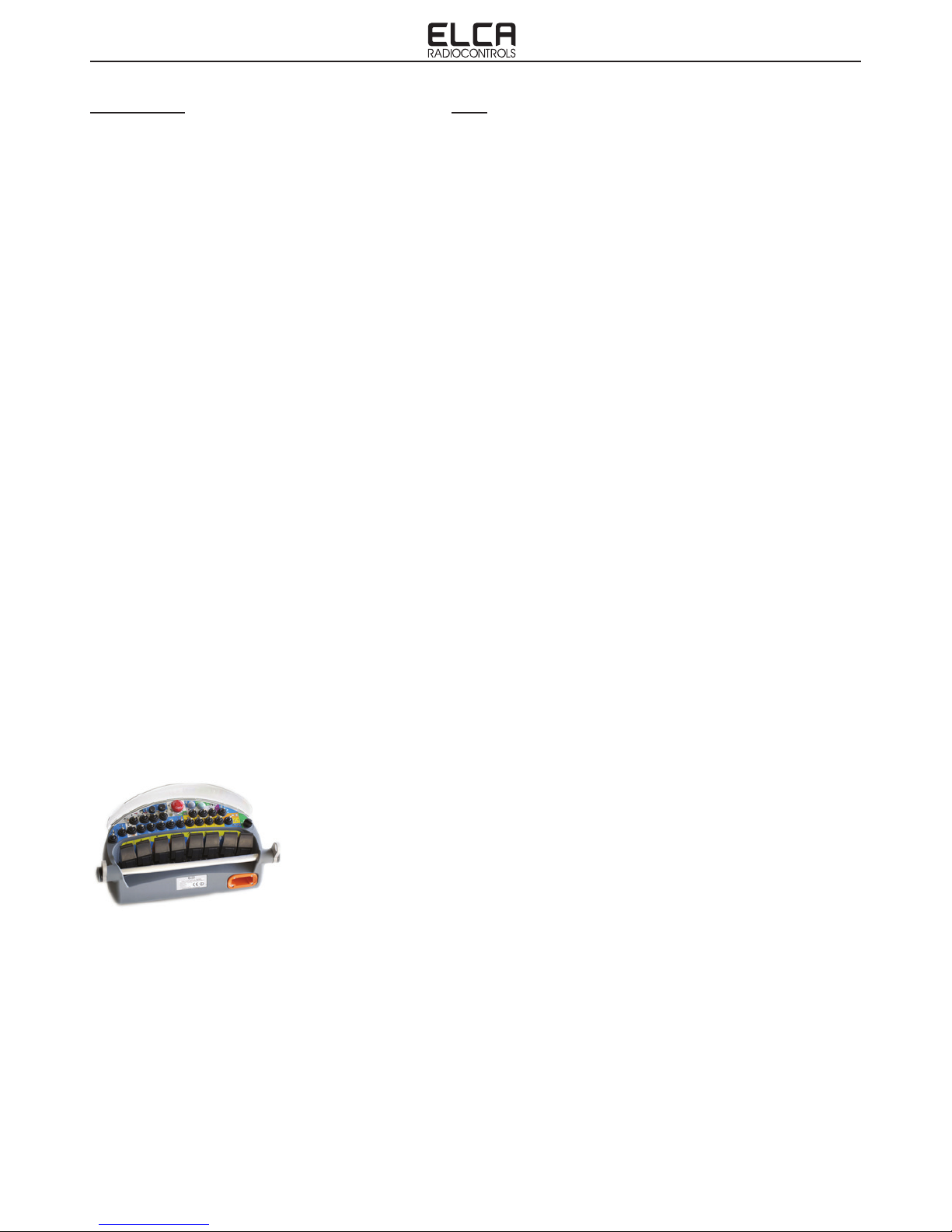
Industrial radio remote control
AT BRAVO-FUNK-915
Transmitting Unit
AR BRAVO-FUNK-915
Receiving Unit


ENGLISH
User manual
ENGLISH


ENG man BRAVO-FUNK-915 00 BRAVO-FUNK-915 Radio remote control system
- Page I -
ENGLISH
INDEX
a. FEDERAL COMMUNICATIONS COMMISSION (FCC) CONFORMITY AND FREQUENCIES . II
a.1 CONFORMITY ..................................................................................................................................................... II
a.2 FCC CONFORMITY STATEMENT................................................................................................................. II
a.3 FREQUENCIES ................................................................................................................................................... II
a.4 MARKET ................................................................................................................................................................ II
1. USER MANUAL................................................................................................................................................................ 1
2. USE INSTRUCTIONS........................................................................................................................................ 2
2.1 GENERAL INFORMATION............................................................................................................................... 2
2.2 APPLICATIONS AND USE CONDITIONS NOT PERMITTED. ............................................................. 2
2.3 INSTRUCTIONS FOR A PROPER AND SAFE USE OF THE RADIO REMOTE CONTROL SY-
STEM. ............................................................................................................................................................................ 3
2.5 INFORMATION FOR INSTALLATION.......................................................................................................... 5
2.6 MAINTENANCE................................................................................................................................................... 7
2.7 WARRANTY.......................................................................................................................................................... 8
2.8 DISPOSAL INFORMATION.............................................................................................................................. 8
3. TECHNICAL DATA............................................................................................................................................. 9
3.1 GENERAL FEATURES...................................................................................................................................... 9
3.2 AT BRAVO-FUNK-915 TRANSMITTING UNIT FEATURES................................................................... 9
3.3 RECEIVING UNIT FEATURES ....................................................................................................................... 9
3.4 CHARGING SYSTEM FEATURES .............................................................................................................. 10
4. TRANSMITTING UNIT .................................................................................................................................... 11
4.1 DESCRIPTION OF OPERATIONS ...............................................................................................................11
5. RECEIVING UNIT .............................................................................................................................................12
5.1 DESCRIPTION OF OPERATIONS .............................................................................................................. 12
5.3 MODIFYING THE PROPORTIONAL FUNCTION PARAMETERS (SETUP) .................................. 14
6. BATTERY CHARGER......................................................................................................................................16
6.1 BATTERY CHARGER USAGE...................................................................................................................... 16
7. TROUBLESHOOTING ....................................................................................................................................17
7.1 TYPE OF TROUBLE ........................................................................................................................................ 17
7.2 TRANSMITTING UNIT FUNCTIONAL CONTROL.................................................................................. 19
7.3 RECEIVING UNIT FUNCTIONAL CONTROL .......................................................................................... 20
7.4 CHARGING CYCLE FUNCTIONAL CONTROL....................................................................................... 21
8. BRAVO-FUNK-915 RADIO REMOTE CONTROL TRANSMITTING UNIT.....................................22
8.1 GENERAL INFORMATION............................................................................................................................. 22
8.2 SPECIAL FUNCTIONS IN DRILLING MODE (WORK).......................................................................... 23
8.3 SPECIAL FUNCTIONS IN DRILLING MODE (WORK) WITH CHARGER....................................... 25
8.4 SPECIAL SAFETY AND MANAGEMENT FUNCTIONS ..................................................................... 25
10. CORRESPONDENCE OF FUNK UNIT FUNCTIONS FOR DRILLING MACHINE ......................26

ENG man BRAVO-FUNK-915 00 BRAVO-FUNK-915 Radio remote control system
- Page II -
Each BRAVO-FUNK-915 series’ radio remote control working in the frequency band 915-928MHz complies with Part 15
of standards FCC and with RSS-210 of IC standards.
Transmitting Unit AT BRAVO-FUNK-915 FCC ID: 2ABS7-ATBRFU915
Receiving Unit AR BRAVO-FUNK-915 FCC ID: 2ABS7-ARBRFU915
This device complies with part 15 of the FCC Rules.
Operation is subject to the following two conditions:
(1) this device may not cause harmful interference, and
(2) this device must accept any interference received, including interference that may cause undesired operation.
Any changes or modications not expressly approved by the party responsible for compliance could void the user’s
authority to operate the equipment.
The radio link between the units of ELCA BRAVO-FUNK-915 series radio remote controls is built at one of the frequencies
permitted by the US standards in force when the system is put on the market.
Frequency band ............................................................................................. 915-928MHz
Transmitting power ........................................................... meets FCC and IC requirements
Available radio channels .............................................................................................. 259
Channel spacing ...................................................................................................... 50kHz
BRAVO-FUNK-915 series industrial radio remote controls communicate either in dynamic or static mode.
Mode is set by the machine manufacturer
Dynamic mode
A radio remote control communicating in dynamic mode:
-uses a working frequency in the band 915-928MHz
-checks that the frequency is free before using it
-continually changes the working frequency to maintain the radio link even when interference occurs.
Static mode
A radio remote control communicating in static mode:
-uses a working frequency in the band 915-928MHz
-checks that the frequency is free before using it
-always works at the same frequency until the stop function is activated.
-BRAVO-FUNK-915 series’ radio remote controls working in the frequency band 915-928MHz can be used in the
United States market.
a. FEDERAL COMMUNICATIONS COMMISSION (FCC) CONFORMITY AND FREQUENCIES
a.1 CONFORMITY
a.2 FCC CONFORMITY STATEMENT
a.3 FREQUENCIES
a.4 MARKET
ENG man BRAVO-FUNK-915 00 BRAVO-FUNK-915 Radio remote control system
- Page 1 -
ENGLISH
Read this Manual before operating the Radio Remote Control.
For ease of reference, symbols have been placed at the side of paragraph titles to highlight the importance of the
information contained in the paragraph.
1. USER MANUAL
Bold face is used to call attention to text that you should read carefully.
This manual has been drawn up entirely by qualied ELCA personnel.
The contents of this manual are subject to change without prior notice, therefore the operator is required to verify
(before using the radio remote control) that the information contained in this publication are consistent with the device
in their possession. Additional information on how the radio remote control works, especially if it is manufactured in
accordance with special requirements of the customer, can be found in the documents annexed to this manual. The
annexed documents must be considered as being an integral part of this manual.
Contact ELCA in the event there are instructions, warnings or indications which may prove to be unclear.
The information provided by ELCA in this manual are regarded as accurate and reliable; however, the company can not
be held responsible for omissions or errors.
This updated edition incorporates suggestions from our Customers to provide an effective tool supporting you in your
day-to-day work.
This manual and any annexed documents are the property of ELCA and all rights are reserved. No parts of this publication
may be reproduced or transmitted in any form or by any means, without written permission from ELCA.
The ELCA logo is a registered trademark of ELCA.
IMPORTANT!
To learn how to operate your radio remote control: operating instructions for radio remote control.
To become familiar with your radio remote control: radio remote control technical data.
To become thoroughly familiar with your radio remote control: detailed information on radio remote
control.
Use instructions of the BRAVO-FUNK-915 radio remote control system for drilling machines.
ENG man BRAVO-FUNK-915 00 BRAVO-FUNK-915 Radio remote control system
- Page 2 -
2. USE INSTRUCTIONS
2.1 GENERAL INFORMATION
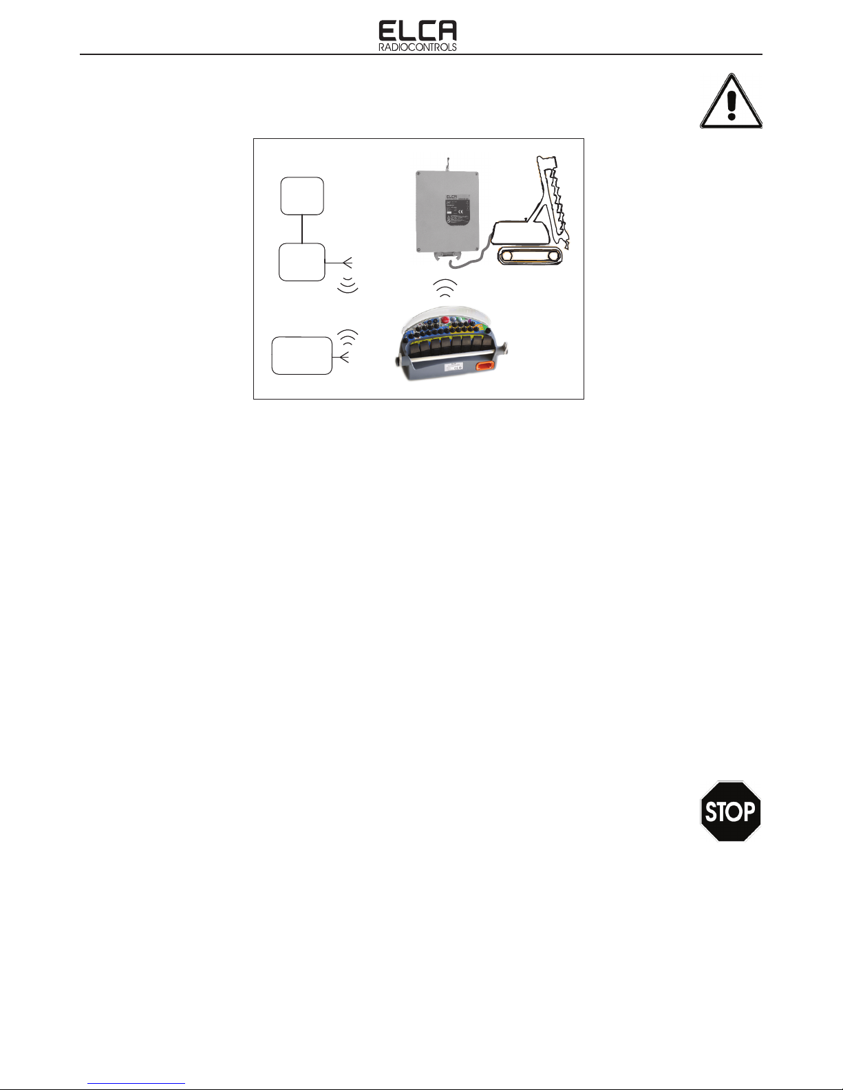
General block diagram
The BRAVO type ELCA Radio Remote Control System is a family of industrial safety radio remote controls that can
be used for the control of lifting, transportation and general equipment on machines where specic safety features are
required on the Stop command (Cat. 3 PL d or cat. 4 PL e) and on the unintended activation of Joystick commands in
the rest position (UMFS Cat. 3 PL d). On request, it is possible to have UMFS with Cat. 3 PL d also on particular On/Off
controls. (in accordance with EN ISO 13849-1)
The BRAVO type radio remote control system is composed of two main parts:
1. The transmitting unit (AT BRAVO-FUNK-915) that allows the user to communicate to the receiver the sequence
of digital data that form the selected command.
2. The receiving unit (AR BRAVO-FUNK-915) that decodes the sequence of digital data and transforms them into
electric impulses that the machine requires to activate the selected command.
The system, which uses electromagnetic waves to transport the control signals, enables the operator to freely move
around the machine giving the possibility to position himself where it is possible to better control its movements and to
choose a safer operating position in total freedom.
The radio remote control is designed in order to be used when an interference-free frequency is activated so as not to
disturb other devices in the vicinity and vice versa not be disturbed. During transmission, the system checks transmission
status and, in the presence of a disturbance, is capable of automatically changing the transmission frequency without
interruptions. Any command transmitted contains a unique code that can not be changed, which makes the activation of
manoeuvres by different transmitters of any brand or model impossible.
2.2 APPLICATIONS AND USE CONDITIONS NOT PERMITTED.
This radio remote control can not be installed in applications in which:
- EXPLOSION-PROOF characteristics are required.
- The movement and/or lifting of persons is made and safety features greater than "PL e" are required on the
STOP command and "PL d" on the UMFS safety function on movements controlled by the Joysticks.
- An alternate current power supply to the receiver and outputs is required.
- Galvanic isolation of the power supply circuit or of the devices connected to the outputs is not guaranteed
when compared to the possible power supply in alternate current.
- The loss of the radio link and the relative shutdown of the receiver outputs may generate dangerous situations.
- The risk analysis has given a negative result.
- Doubt concerning the operation of the radio remote control remain.
MACHINE
RECEIVING
UNIT
TRANSMITTING
UNIT
MACHINE
RECEIVING
UNIT
ELECTROMAGNETIC
WAVES
TRANSMITTING
UNIT
ENG man BRAVO-FUNK-915 00 BRAVO-FUNK-915 Radio remote control system
- Page 3 -
ENGLISH
2.3 INSTRUCTIONS FOR A PROPER AND SAFE USE OF THE RADIO
REMOTE CONTROL SYSTEM.
IMPORTANT! Radio remote control user MUST:
-Check the correct mechanical operation of the STOP button before every operation.
-Check the correct operation of the control devices.
If there is a deterioration in the correct operation of the STOP button or functional abnormalities in the control devices, the
use of the radio remote control must be prohibited until the full restoration of the system's functionality.
-Use the transmitter unit by holding it or fastening it to the body in a safe and stable manner to avoid it accidentally
falling.
-Be thoroughly familiar with the functions and features of the radio remote control and of the machine the receiving
unit is connected to.
-Before activating any movement of the machine, ensure that the operator's position is such to ensure that:
-There is no danger of tripping.
-There is no danger of loss of balance.
-It is impossible that small-sized objects can introduce themselves between the command actuators and
involuntarily activate an operation.
-Allow to follow the movements of the machine and the load in view.
-Guarantee the safety conditions concerning those engaged in other operations, activities or work in the
work area of the machine and operator.
-Turn off the transmitting unit whenever the work is suspended, even momentarily, even if the device is equipped
with automatic shut-off.
-Switch-off the transmitting unit and disconnect the power supply of the receiver before performing any maintenance
on the radio remote control or on the machinery.
-Do not leave the transmitting unit unattended and switched on.
-Remember that the transmitting unit can operate the machine even when placed indoors and far from the receiving
unit, so improper use can cause severe damage to people and property.
-Never wash the units with water jets, use a damp cloth only.
-Do not use in shielded environments (e.g. inside the drum of the mixer).
-Charge the batteries in an environment that is not too hot, too cold, too humid or dusty.
-Keeping the batteries partially charged at all times can extend their useful life.
-Do not leave the batteries discharged for long periods.
-Charge the batteries at least once a year even if the unit has not been used since the last charge.
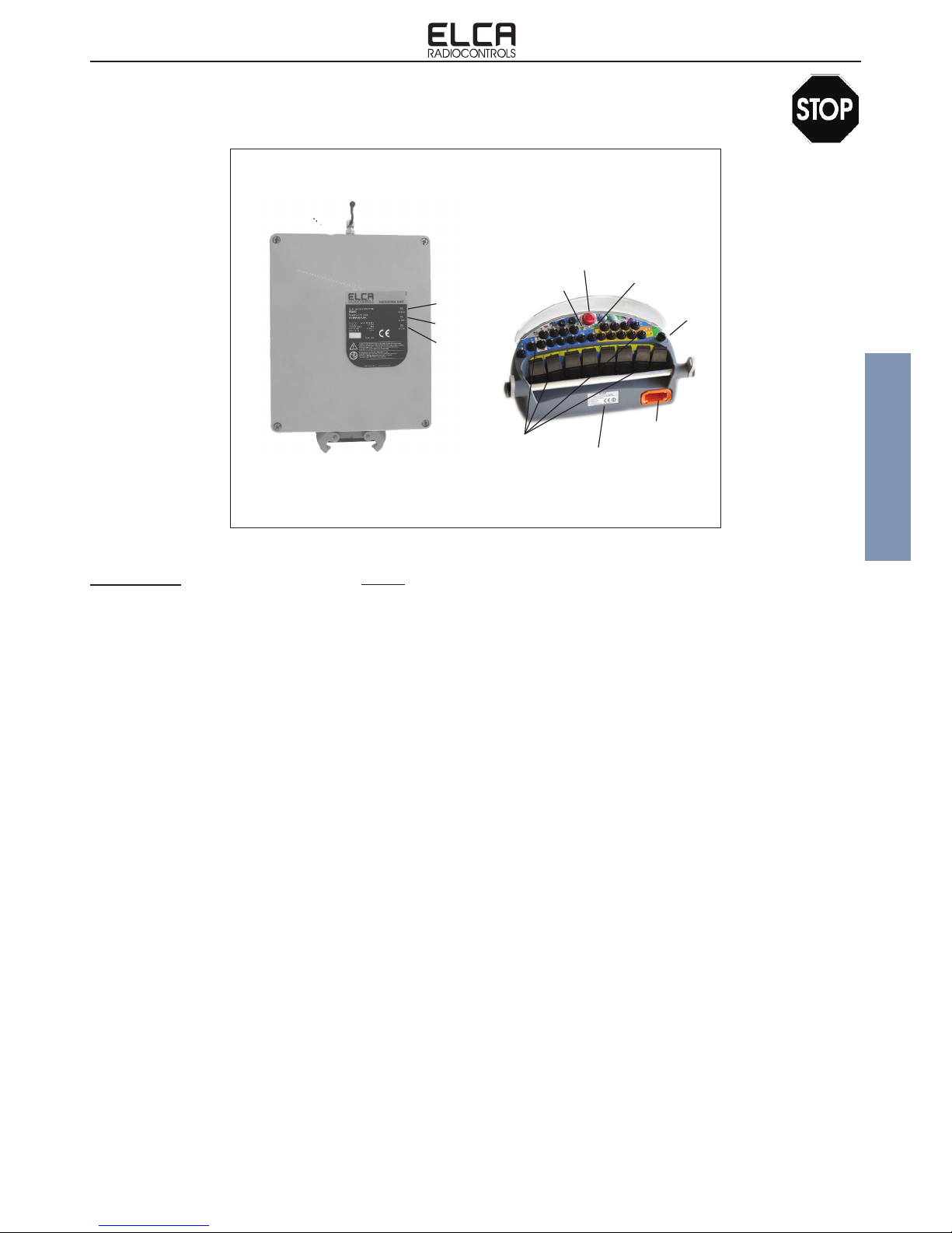
TRANSMITTING
UNIT
RECEIVING
UNIT
Command
actuators
Battery
Battery Check
light
Option Check
LED
Starting
keyswitch
STOP mushroom button
ANTENNA
POWER light
ALARM light
STATUS light
4 Mounting points
with vibration dampers
with vibration dampers
Cable output
Rating plate
Rating plate
ENG man BRAVO-FUNK-915 00 BRAVO-FUNK-915 Radio remote control system
- Page 4 -
IMPORTANT ! The installer of the radio remote control must:
-Carry out a thorough risk assessment on the use of the machine with the radio remote control.
-Assess that there are no hazardous conditions in the event the radio remote control stops due to the loss of the
radio link.
-Do not install the radio remote control on machines in which the safety of moving, lifting or transporting people is
entrusted to the radio remote control with inadequate PL commands.
-Do not install the radio remote control where explosion-proof characteristics are required of the radio remote
control (EX).
-Secure the receiver so that it is always facing the transmitter in normal use.
-Ensure that there are no metal obstacles between the transmitter and receiver or obstacles that may interfere with
the transmission of electromagnetic waves.
-Choose the installation of the receiver in a vertical position and easily accessible for maintenance operations.
-Avoid that the receiver is subjected to strong vibrations. Use vibration dampers if necessary.
-Always make sure that the value of the supply voltage complies with the rated voltage indicated on the rating plate
of the receiver.
-Use multi-pole connectors for the electrical connection of the receiver to the machinery to allow easy removal if
required.
-Use cables of suitable section, max. 1.0 mmq (AWG 16).
-Connect the Stop circuit making sure that the current circulating therein does not exceed the value of the protection
fuse.
-Distribute the common wire to the functions interposing always the Safety relay.
-After installation check that the stop circuit works correctly.
-Check that all limit switches, load or position limiters are working correctly.
-Ensure that all manoeuvres are functioning correctly and are consistent with the symbols placed on the transmitter.
Denition of the key functions:
-Whenever a new match key is connected to a transmitter module, it is necessary
to perform the procedure for the acquisition of the identication code. Press the
Stop mushroom button, bring the keyswitch selector in position 1, press the Start
button for approximately 10 seconds, until the green LED stops blinking. In new
radio remote controls, the identication code has already been acquired.
Switching on and switching off:
-ENABLING THE TRANSMITTER. Check that the Mushroom pushbutton is in rest
position (lifted) and bring the keyswitch selector in position 1. If the receiver is
powered, the transmitter instantly activates a communication channel and the green
LED (Battery Check) ashes fast.
-START-UP. After having enabled the transmitter, bring the keyswitch in position Start
(if applicable) or, in general, activate the START command. Now the green LED
ashes slowly and the system is on. Every transmitted command is now activated
by the receiver.
-SWITCHING OFF THE TRANSMITTER. Press the Mushroom pushbutton or bring
the keyswitch selector in position 0.
Safety function:
-PASSIVE EMERGENCY: In case the receiver can no longer correctly interpret the
signals transmitted by the Transmitter to interrupt the radio connection, the receiving
unit automatically stops, deactivating all the outputs and opening the Stop circuit.
Intervention time of the passive emergency is under 500 ms.
-ACTIVE EMERGENCY: With the radio remote control on, when pressing the
mushroom button the Stop command is transmitted and the receiver turns off all
outputs and opens the stop circuit. Intervention time under 130 ms
-SAFETY COMMAND: The Safety command is transmitted whenever a joystick
is placed outside position zero. This is used to ensure greater protection from
unintended movements with the actuator in rest position (UMFS).
Acquisition of identication code:

ENG man BRAVO-FUNK-915 00 BRAVO-FUNK-915 Radio remote control system
- Page 5 -
ENGLISH
2.5 INFORMATION FOR INSTALLATION
The installation must necessarily be carried out by qualied and, if need be, licensed staff, as required by the provisions
of law of certain Countries. Installation is really important, because the safety of the machinery, its proper operation and
the ease of performing an effective maintenance on the Radio Remote Control depend on it.
In addition to all information made available by the machine manufacturer, the installer should always take the following
precautions:
- Perform a thorough risk assessment considering the use of the machine by means of the radio remote control.
- Apply and comply with the provisions of the reference standards for the eld of application of the machine on which
installation is being performed.
- Position the receiver unit so that it is easily accessible for maintenance operations.
- Connect the receiver unit to the machine using multi-pole connectors so that it can be easily disconnect in the event
that it needs to be sent to a service centre.
- Position the receiving unit vertically, so that the antenna is facing the operating position of the operator, and so as
to optimise the working range of the radio remote control.
- Position the receiving unit so that it is the farthest possible from metal objects. Do not position the receiving unit
inside containers made out of metal or other conductive material, without having provided for the installation of an
external antenna.
- Avoid exposing the receiver unit to strong vibrations. If necessary, use appropriate anti-vibration systems.
- Use cables with suitable section for wiring connections.
- The power supply of the receiver unit must be protected against short circuit.
- Provide for the possible disconnection of the power supply to the receiving unit during installation, wiring and
maintenance operations.
- Warning. Never supply voltage from the outside toward the outputs of the receiver, even when the radio remote
control system is off. Return voltage through the outputs may limit or exclude the safety performance of the radio
remote control.
Indicator lights
-SYSTEM ON IN WAIT FOR START: The green Battery Check LED ashes rapidly.
-INDICATION OF SYSTEM ON. When the system is working properly and the battery
is fully charged, the green Battery Check LED ashes slowly.
-INDICATION OF LOW BATTERY. When the battery is low, the Battery Check LED
slowly ashes red, signalling there are approximately 10 minutes of power reserve left.
-ERROR - STOP MUSHROOM ENABLED: The Battery Check LED ashes red
once, then switches off when the system detects that the Stop Mushroom button is
enabled, when activated.
-ERROR - ON/OFF COMMAND ENABLED: The Battery Check LED ashes red
twice, then switches off when the system detects that the ON/OFF command is
enabled, when activated.
-ERROR - LOW BATTERY: The Battery Check LED ashes red three times, then
switches off when the system detects that the battery is low, when activated.
-ERROR - JOYSTICK OUT OF ZERO: The Battery Check LED ashes red four
times and then switches off when the system detects a joystick out of zero, when
activated.
-INDICATION OF DAMAGED TRANSMITTER: The Battery Check LED stays on red
for two seconds, then switches off.
Sound signals:
-When the Red LED that indicates an error or Low Battery goes on, the transmitter
emits a sound signal.

ENG man BRAVO-FUNK-915 00 BRAVO-FUNK-915 Radio remote control system
- Page 6 -
- Use decoupling systems for the receiver outputs when an electrical command other than the radio remote control is
foreseen, except when use of the alternative command is made with the receiving unit of the radio remote control
electrically disconnected from the machine.
- Pay attention to the current in the STOP and SAFETY outputs so that it never exceeds the permitted value of 7.5A.
- The SAFETY relay contact must be connected in series to the common wire of the movement command when
the safety protection is required in relation to the involuntary activation of the control with actuator at rest (UMFS
unintended movement from standstill PL d). This connection is already prearranged internally for the ON/OFF or
PWM outputs of the Joysticks.
- IT IS IMPERATIVE that the two STOP contacts on the receiver are always used.
- It is necessary to always have a positive voltage (8-30 V) in the inputs IN_STP1 (K1), IN_STP2 (J1) and IN_SAFETY
G1), otherwise the receiver cannot function.
- If the machine is congured to manage only one Stop command, connect the input IN_STP1 (K1) to the positive
pole, connect the two STOP contacts in series, connecting OUT_STP1 (K2) to IN_STP2 (J1) with a bridge; output
OUT_STP2 (H1) is now the Stop output. The Stop contact is now located between the terminals IN_STP1 and
OUT_STP2, with the need to have current ow from IN_STP1 toward OUT_STP2.
- Connecting the two STOP contacts separately if the machine is set to manage two separate Stop contacts (use four
wires). In this case, always connect the positive pole to the inputs IN_STP1 and IN_STP2. Current must always
ow from the input to the output. The installer is responsible to perform the wiring able to guarantee the level of
security required.
- Gather up the wiring cables and lock them into place, so that the weight cannot tear the crimped contacts of the
single cables. If need be, use the included spring to be mechanically fastened to the connectors of the receiver and
fasten the wires with a plastic strip.
- After installation, test the machine operated by the radio remote control, checking the actual safety of the machine
by means of the STOP command, the exact correspondence of the command symbols with the actual movement
of the machine.
- Check that operations that render the machine's safety systems ineffective are not performed during installation
(limit switches, interlocks, load limiters, etc..).
- Check that the contact of the SAFETY command is in series with all commands to which a UMFS protection is
required.
- Check also the correct operation of the machine without the use of the radio remote control where possible.
- Make sure that the activation of the auxiliary commands on the machine (if electrical) does not entail the application
of voltage to the outputs of the receiver. If need be, use decoupling systems (see paragraph 5.2). Return voltage
through the outputs may limit or exclude the safety performance of the radio remote control.
- If abnormal operations are experienced, DISABLE the machine until the problem is fully solved.
- When closing the receiving unit again, carefully check the integrity of the sealing gasket and its correct housing.
Press the connector until the two aps on the cover slot into place (conrmed by a clicking sound).
ENG man BRAVO-FUNK-915 00 BRAVO-FUNK-915 Radio remote control system
- Page 7 -
ENGLISH
Before proceeding with any kind of maintenance make sure the receiver is not powered, that the transmitter is switched
off and the emergency STOP button pressed.
In the event it is necessary to intervene on the machine or on the receiving unit for maintenance operations, electrically
disconnect the receiver unit from the machine.
Even though the radio remote control system does not require special maintenance operations, some precautions are
nevertheless necessary so that it remains fully efcient at all times.
Controls to be carried out daily before using the Radio remote control:
-Check that all the command symbols are clearly visible.
-Check that the mushroom Stop pushbutton works properly: the pressure exerted on the button must not be high and
the reset must take place without friction or forcing.
-With the mushroom button pressed, press the Start command. The red Battery Check LED must switch on.
-Check the integrity of the transmitter's plastic casing. It should not have cracks.
-Check the integrity of the rubber of the command actuators (joysticks, toggle switches, pushbuttons, etc.). It should
not have cracks or holes.
-Once you have nished using it, remove any deposits and clean it with a cloth.
Controls to be performed weekly:
-Clean the transmitter with a damp cloth and verify its integrity.
-Clean the springs of the battery holder and of the batteries.
-Clean the springs of the battery holder placed on the battery charger.
-Check the integrity of the receiving unit. The casing should not have cracks.
Controls to be performed monthly:
-Clean the receiving unit with a damp cloth and assess its integrity.
-Check the connection of the antenna on the receiver.
Controls to be performed yearly:
-Open the receiving unit and verify the integrity of the internal components. There should be no residual moisture
or oxidation.
-Check the integrity of the receiving unit's gasket on the cover.
-Check cable seal.
-Fully recharge the batteries in the event of prolonged disuse of the system.
In addition to the above recommendations, in order to maintain the efciency of the radio remote control System, the
following precautions should be carried out:
-Protect the transmitting unit from jets of water or rain.
-Remove the receiving unit if it is installed externally during transport. In case of rain during transport, the receiving
unit's IP level may not be sufcient to prevent water seepage, if it is directly exposed to the rain.
-Do not leave the transmitter unnecessarily exposed to direct sunlight or heat sources.
Should it be necessary to send the Radio Remote Control system to a service center to have it repaired, it is important to
send the Transmitter along with the Receiver. Only by doing so can we guarantee the System will be certainly repaired
and returned fully functional. Contact the service center in advance before proceeding to send the material and include
a description of the abnormal condition encountered in the packing or in the waybill.
2.6 MAINTENANCE
ENG man BRAVO-FUNK-915 00 BRAVO-FUNK-915 Radio remote control system
- Page 8 -
The Elca Radio Remote Control System type BRAVO is covered by a 24-month warranty starting from date of purchase
as evidenced by the way bill, that must also state the serial number of the Radio Remote Control System.
Warranty covers defects of manufacture of the radio remote control system and its components, when such defects have
been determined to exist at Elca's sole discretion.
The battery pack is covered by a warranty of 12 months, starting from the date of its purchase.
User shall arrange the delivery to / collection from Elca authorised service centres and defective parts shall be replaced
at no additional charge.
In the event of on-site servicing/repair, travel and personnel expenses shall be charged to the user, whereas the
replacement of any defective parts shall be free of charge.
Servicing/repair by unauthorised persons, improper use or improper installation shall make the warranty null and void.
Warranty does not cover transport damage or loss.
Elca shall not be held liable for damage to property or persons.
Elca shall not be liable for machine down time and it is the user's responsibility to provide the option of manual or cable
control for each machine.
Any disputes shall be submitted to the Court of Bassano del Grappa (Vicenza, Italy).
2.7 WARRANTY
The radio remote control should be disposed of at a differential waste recovery service at the end of its useful life.
DISPOSAL OF BATTERIES, Directive 2006/66/EC and subsequent amendments.
Batteries may release toxic substances harmful to humans, animals and plants and contaminate the environment. They
should be not disposed of with municipal solid waste but delivered to authorised collection centres for battery recycling
and treatment.
Users' contribution to collect and recycle batteries is critical to minimising the potential impact of the contaminants used
in these components on the environment and human health.
The European Union has set up different battery collection and recycling systems. For information on the method adopted
in your area, contact your local authorities.
The crossed-out wheeled bin symbol on the batteries means that batteries must be disposed of separately from household
waste in compliance with Directive 2006/66/EC and subsequent amendments and with local regulations.
2.8 DISPOSAL INFORMATION

ENG man BRAVO-FUNK-915 00 BRAVO-FUNK-915 Radio remote control system
- Page 9 -
ENGLISH
GENERAL FEATURES.
Manufacturer ......................................................................................................................................................ELCA S.r.l.
Radio Remote Control System type .......................................................................................................................BRAVO
Working frequency..........................................................................................................................915.050 - 927.950 MHz
Channel spacing used ............................................................................................................................................. 50 kHz
Working temperature .......................................................................................................................................-25 - +55 °C
Storage and transportation temperature...........................................................................................................-25 - +55 °C
Operating range......................................................................................................................................................... 100 m
Command response time ..................................................................................................................................... < 130 ms
Active Stop time....................................................................................................................................................... < 130 s
Passive Stop time (maximum stop time) .................................................................................................................. < 0,5 s
Performance Level of the safety functions in accordance with EN ISO 13849-1
Protection of .........................................................................................................................PL d stop (wiring with 2 wires)
Protection of .........................................................................................................................PL e stop (wiring with 4 wires)
Protection from unintended movements from the rest position of the Joysticks (UMFS) ............................................ PL d
3.1 GENERAL FEATURES
3. TECHNICAL DATA
Model................................................................................................... AT BRAVO-FUNK-915
Transceiver radio module .........................................................................................RTA-AU1
Incorporated ...............................................................................................................antenna
Distance between the antenna and the human body ................................................. > 20 cm
Battery pack....................................................................................power supply: Li-ion 7.4 V
Current draw.............................................................................................................< 130 mA
Absorbed power ........................................................................................................... < 1 W
RF effective radiated power.............................................................................. < 25 mW ERP
Run time with fully charged battery at 20 °C ......................................approximately 20 hours
Run time after battery low warning:................................................approximately 10 minutes
Protection degree .............................................................................................................IP65
Dimensions ................................................................................................ 420x200x250 mm
Weight ..........................................................................................................................2600 g
Model.................................................................................................. AR BRAVO-FUNK-915
Transceiver radio module .........................................................................................RTA-AU1
External .....................................................................................................................antenna
DC power supply: .................................................................................................... 8-30 V ]
Maximum absorbed current............................................................................................ < 1 A
Absorbed power ........................................................................................................... < 5 W
STOP contacts protection fuses (MINI® Blade Fuse) ....................................... F3, F4= 7.5 A
SAFETY contacts protection fuse (MINI® Blade Fuse).......................................... F5 = 7.5 A
SAFETY contacts protection fuse (MINI® Blade Fuse).......................................... F1 = 3.0 A
Power supply protection fuse (MINI® Blade Fuse) ................................................ F2 = 7.5 A
Maximum permitted voltage ....................................................................................... 30 V ]
Maximum rated current of proportional outputs in current (PWM)......................... 2 A (30 ])
Maximum rated current of ON/OFF outputs .......................................................... 4 A (30 ])
Maximum rated current of proportional outputs in voltage ............................10 mA (28 V ])
Protection degree ............................................................................................................ IP65
Dimensions ................................................................................................ 230x280x110 mm
Weight ..........................................................................................................................1200 g
3.2 AT BRAVO-FUNK-915 TRANSMITTING UNIT FEATURES
3.3 RECEIVING UNIT FEATURES
ENG man BRAVO-FUNK-915 00 BRAVO-FUNK-915 Radio remote control system
- Page 10 -
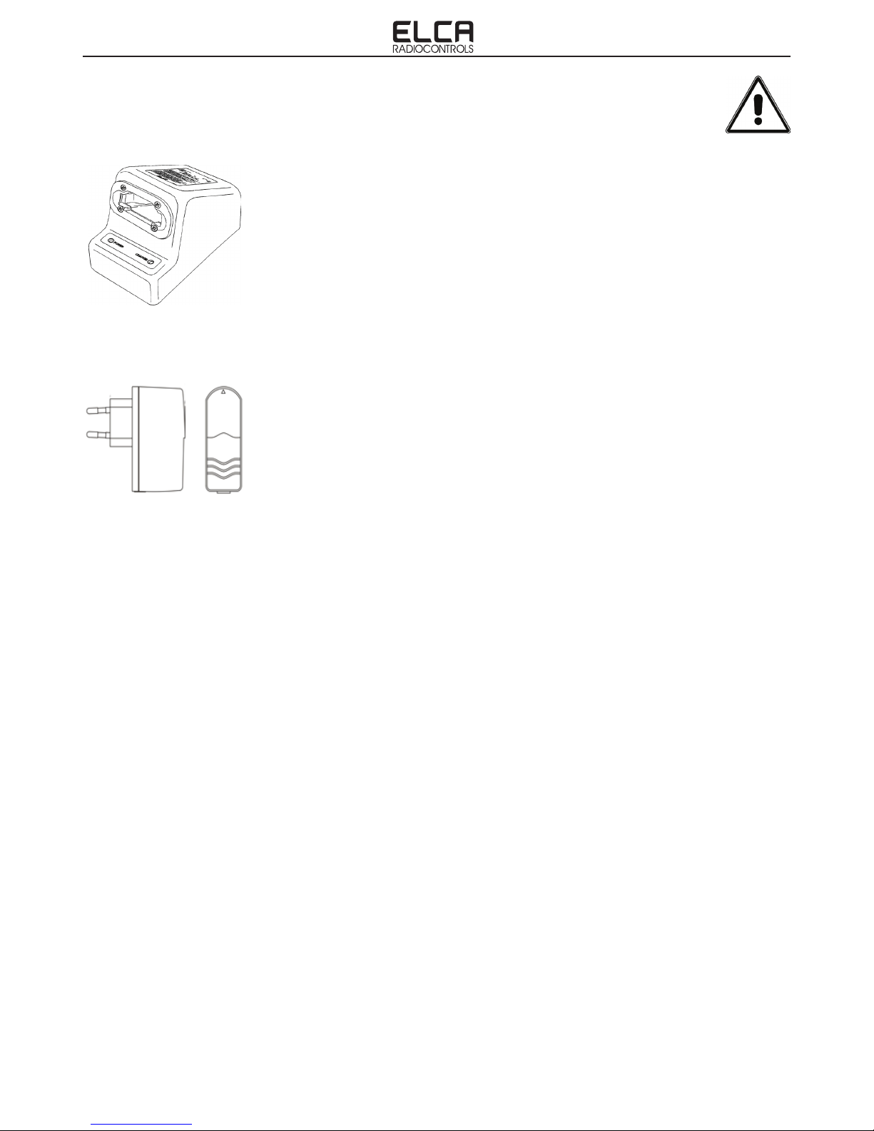
Battery charger for battery pack LI-TE (7.4V - 17Wh [2.3Ah]) with Li-ion chemistry
Battery charger model ............................................................................................. LITE-ION
Power supply voltage ............................................................................................ 12-30 V ]
Absorbed current............................................................................................................ < 1 A
Rated output voltage ................................................................................................. 8.4 V ]
Rated output current...........................................................................................................1 A
Full recharging time ........................................................................................approx 4 hours
Charge time for 2 hours of run time .........................................................approx. 20 minutes
Working temperature ............................................................................................... 0 +40 °C
Protection degree ........................................................................................................... IP40
Dimensions ....................................................................................................144x84x92 mm
Weight ............................................................................................................................300 g
Stabilised external AC/DC power unit for wall socket for LITE-ION battery charger
Input ..........................................................................................100-240Vac 50/60Hz 450mA
Output.......................................................................................................... 12V= 1.5A (18W)
Plug ...................................................................... Eurospina (Euro-plug) Type C (EEC 7/16)
Dimensions.............................................................................................. 59.3x30.7x75.6 mm
Weight ............................................................................................................................120 g
3.4 CHARGING SYSTEM FEATURES
ENG man BRAVO-FUNK-915 00 BRAVO-FUNK-915 Radio remote control system
- Page 11 -
ENGLISH
The receiving unit AT BRAVO-FUNK-915 comprises three main electronic circuits:
-RADIO TRANSMITTING BOARD. Containing all the electronics for the transmission and management of the working
frequency.
-INTERFACE CARD. Containing all the electronics for the management of the command inputs and signal encoding
-IDENTIFICATION CODE CARD. Containing the unique identication code of the system.
-TX EXTENSION CARD. Permits to increase the available commands.
The transmitting unit AT BRAVO-FUNK-915 univocally communicates with the receiver with its own receiver, because
the transmitted signal contains an identication code inside it that is not reproducible. Recognition of this code allows the
receiving unit to identify with certainty the unit that has transmitted the command. In this way any other device, different
or the same type, that is transmitting on the same frequency can not in any way replace the control of the machine to
which the system is connected. Any radio transmissions on the same working frequency as our transmitter or any radio
frequency disturbances can in the worst case only switch off the receiver with all outputs disabled (see description of
receiving unit operation).
When a new match key is mounted to the transmitter, it is necessary to perform the procedure for the acquisition of the
identication code. By means of the identication code acquisition procedure, the transmitter acquires the information
contained on the match key. The procedure is arranged for the Stop mushroom button to be activated with the transmitter
switched off; bring the starting keyswitch in position 1 and activate the Start command for approximately 10 seconds, until
the Battery Check LED ashes green. Any error signals are not to be taken into consideration in this precise instant. After
4.1 DESCRIPTION OF OPERATIONS
4. TRANSMITTING UNIT
the acquisition procedure, only the receiver with the hardware key containing the same
identication is enabled to activate the commands transmitted by the transmitter.
During normal use, when the keyswitch selector is brought into position 1, if the system
does not encounter abnormal conditions, the Battery Check LED starts rapidly blinking
green. When the Start command is pressed, the LED starts blinking slowly, to indicate that
the system is working.
With the keyswitch in position 1, the system runs checks on the status of the Transmitter
and, if it detects abnormal conditions, the following error statuses are displayed:
- Red Battery Check LED on for 2 seconds. The transmitting unit is not working properly or
the procedure for the acquisition of the identication code has not been activated.
- Red Battery Check LED on for 1 second. The Stop pushbutton has been detected as
being on or not working.
- Red Battery Check LED ashes 2 times. An ON/OFF command has been detected as
being on.
- Red Battery Check LED ashes 3 times. The battery has been detected as being low.
- Red Battery Check LED ashes 4 times. A joystick has been detected as out of position
zero.
Note. A sound signal is emitted when the red LED goes on.
During normal operation of the radio remote control, the red LED starts blinking when the
battery is low and approximately only 10 minutes of run time are left.
Certain ON/OFF functions or certain proportional functions can be installed during assembly
of the unit as functions that can be enabled when the transmitter is activated, without
generating an error condition. More detailed information on this type of commands can
be found in the documentation annexed to this manual that describes special customised
radio controls, built in accordance with precise technical specications of the customer.

ENG man BRAVO-FUNK-915 00 BRAVO-FUNK-915 Radio remote control system
- Page 12 -
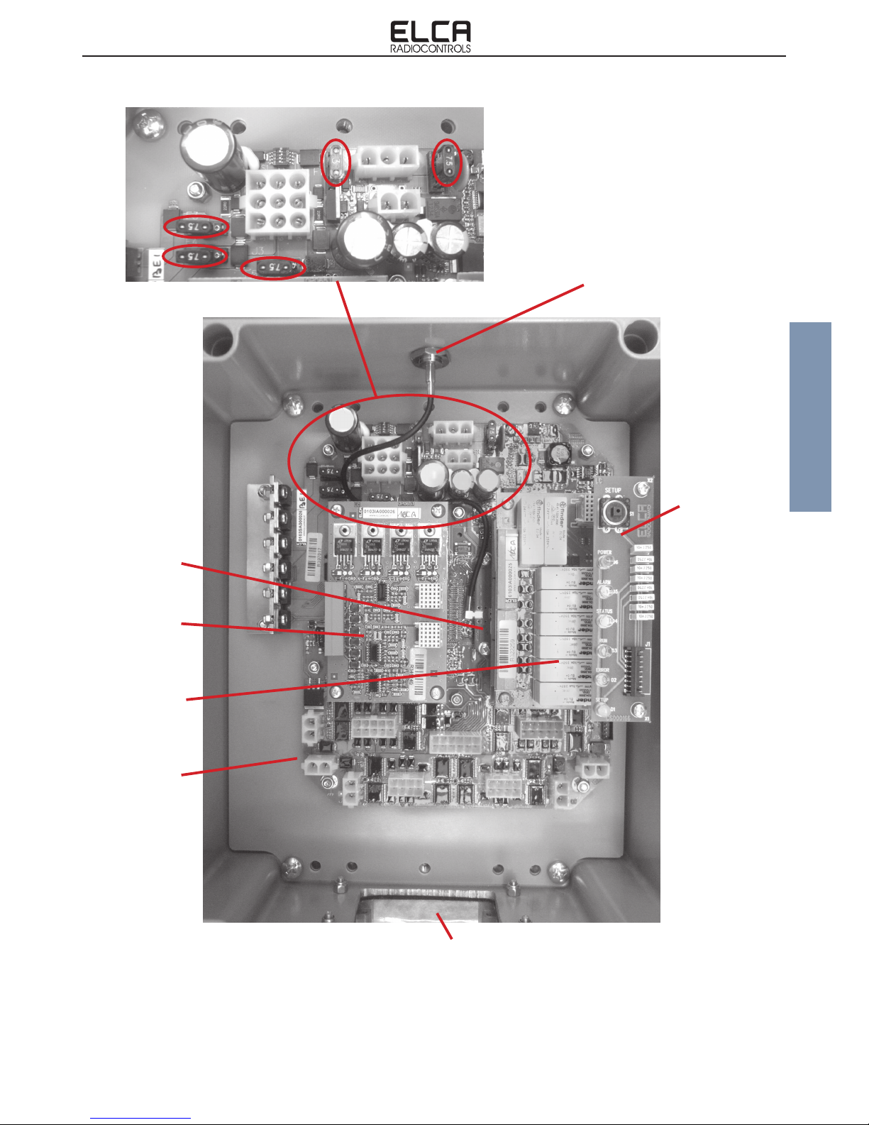
The receiving unit AR BRAVO-FUNK-915 comprises several main electronic circuits:
-MOTHER BOARD. This contains the electronics for the decoding and implementation of the controls, the safety
fuses, and backs up the radio module, the encryption key, the data memory and the expansion cards.
-RADIO RECEIVER CARD. Contains all the electronics for the reception and management of the working frequency.
-IDENTIFICATION CODE CARD. Contains the unique identication code of the system. This code allows the system
to only recognise the signals transmitted from the transmitter having the same identication code.
-DATA MEMORY CARD. Contains all the parameters for the adjustment of the proportional outputs inside it.
-LED CARD. Backs-up the signalling LED to monitor the system.
-ON/OFF AND PROPORTIONAL COMMANDS EXPANSION CARDS. Increase the number of commands available.
5.1 DESCRIPTION OF OPERATIONS
5. RECEIVING UNIT
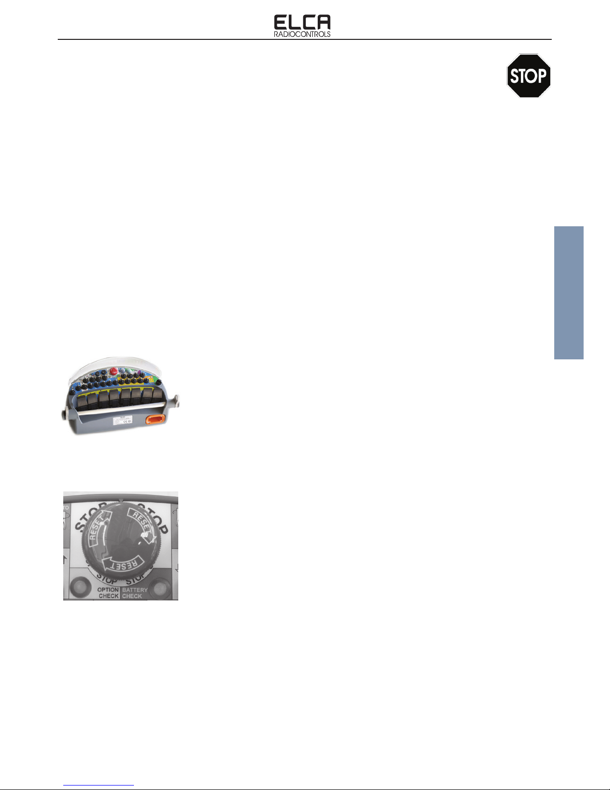
From the outside, the receiving unit allows the user to check the system's operating status through the LEDs.
The information that can be obtained are:
-Green Power LED off: The unit is not powered.
-Green Power LED on: The receiving unit is powered, but no radio connection is enabled.
-Green Power LED blinking slowly: There is a radio connection with the transmitter.
-
-Red Alarm LED Off: No abnormal condition.
-Red Alarm LED ashes 1 time per second: Error in the STOP channels.
-Red Alarm LED ashes 2 times per second: Error in the SAFETY channel.
-Red Alarm LED xed on: The unit is not working properly.
-Blue Status LED Off. The unit is not activated.
-Blue Status LED ashes slowly: There is a power supply voltage greater than the required one.
-Blue Status LED ashes rapidly: The receiving unit receives data from the transmitting unit.
Other signalling LEDs are made visible by removing the cover.
The RUN and ERROR LEDs are not used, while the yellow “Setup” LED signals:
-Yellow Setup LED Off. The receiving unit is working properly.
-Yellow Setup LED ashes 1 time per second: There is an error in the encoding key.
-Yellow Setup LED ashes 2 times per second: There is an error in the data memory card.
-Yellow Setup LED ashes 3 times per second: The receiving unit is in the process of saving the adjustment parameters.
-Yellow Setup LED On. The receiving unit is in Remote Setup mode.
POWER LED
SETUP
BUTTON
SETUP LED
ALARM LED
STATUS LED
ANTENNA
CONNECTOR
ENG man BRAVO-FUNK-915 00 BRAVO-FUNK-915 Radio remote control system
- Page 13 -
ENGLISH
CONNECTOR OPENING
INTERNAL FUSES
LED CARD
MOTHER
BOARD
RADIO CARD
RECEIVER
COMMANDS
EXPANSION CARD
PROPORTIONAL
COMMANDS
EXPANSION CARD
ON/OFF
ANTENNA
F2
F1
F3
F4 F5

ENG man BRAVO-FUNK-915 00 BRAVO-FUNK-915 Radio remote control system
- Page 14 -
5.3 MODIFYING THE PROPORTIONAL FUNCTION PARAMETERS (SETUP)
The parameters of the proportional functions can be changed by applying the SETUP procedure and involves the
modication of the following parameters:
-Calibration of maximum and minimum values of each proportional function with output in voltage or in current (PWM).
-Calibration of proportional values in voltage in rest position (OFFSET).
-Inversion of movement direction of the Joystick axle.
-Reset to default Factory settings.
SETUP enabling.
Before proceeding to change the parameters of the proportional functions, it is necessary to enable the SETUP function.
-Open the receiver cover.
-Power the receiver.
-Press the SETUP button inside the receiver on the LED card.
-The yellow SETUP LED is on xed.
Receiving SETUP button SETUP LED P+/P- selector
Change maximum value.
-With the SETUP function enabled, check that all the proportional functions are in rest position. For the potentiometers,
the rest position is with the potentiometer rotated counter-clockwise. Proportional functions out of zero prevent
proper operation of the SETUP function. The presence of two or more proportional functions simultaneously out of
zero is indicated by the rapid ashing of the SETUP LED.
-Move the Joystick of the function you want to adjust to the maximum and hold it in position.
-By operating the selector in which P+ / P- is indicated, you will change the maximum value of the function by either
increasing or decreasing it.
-Press the STOP pushbutton to save the changed value. Switch off the receiver to cancel any changes.
Change minimum value.
-With the SETUP enabled, move the Joystick of the function you want to adjust just slightly out of zero and hold it in position.
-By operating the selector in which P+ / P- is indicated, you will change the minimum value of the function by either
increasing or decreasing it.
-Press the STOP pushbutton to save the changed value. Switch off the receiver to cancel any changes.
Adjustment of the values at rest of the outputs in voltage (OFFSET).
-With the SETUP function enabled, check that all the proportional functions are in rest position. The presence of two
or more proportional functions simultaneously out of zero is indicated by the rapid ashing of the SETUP LED.
-On the Transmitter, activate and release the selector with P+/P- indicated from the P+ side and immediately after
activate and release the Start command.
-Repeat the operation described above until the SETUP LED starts blinking three times.
-Move the Joystick or the potentiometer of the function you want to adjust just slightly out of zero and hold it in position.
-By operating the selector in which P+ / P- is indicated, you will change the OFFSET value of the function by either
increasing or decreasing it.
-Press the STOP pushbutton to save the changed value. To perform other adjustments, bring the Stop in rest position,
press Start and resume operations from the two points described above we have just discussed. Switch off the
receiver to cancel any changes.
-To exit the adjustment mode of the Offset voltage, it is necessary to exit the SETUP mode, switching the receiver off
or moving the Elca Logo of the cable protection hood for approximately 10 seconds near to the area on the receiver
indicated with Enable SETUP.
This manual suits for next models
2
Table of contents
Other ELCA Remote Control manuals


