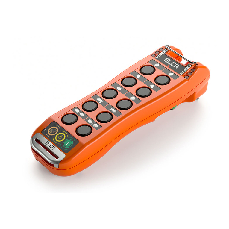
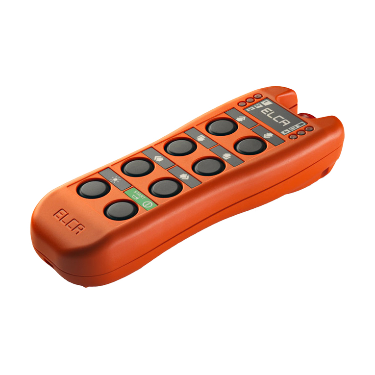
ELCA GENIO User manual

RADI
O
C
O
NTR
O
LS
ELCA S.r.l. Via del Commercio,7/b - 36065 Mussolente (VI) ITALY
www.elcaradio.com tel. +39 0424 578500 fax +39 0424 578520
MANUEL D’UTILISATION
BEDIENUNGSANLEITUNG
MANUAL DE USO
USER MANUAL
MULTI_Man_GenioSFERAE_03 0408MA000234


Multi_INDEX_Man_GenioSFERAE_03
GENIO-SFERA.E Radio remote control s stem
- Page i -
INDEX
ENGLISH ................................................................................. PAGE 1 - 14
FRANÇAIS............................................................................. PAGE 15 - 28
DEUTSCH.............................................................................SEITE 29 – 42
ESPAÑOL ..........................................................................PÁGINA 43 – 56
ANNEX................................................................................... PAGE 57 - 66

Multi_ING_Man_GenioSFERAE_03
GENIO-SFERA.E Radio remote control system
- Page 1 -
1. USER MANUAL
It is recommended that this manual be read carefully before using the Radio Remote Control.
To make reading easier, each Heading is accompanied by a symbol indicating the importance of the contents.
SYMBOL SIGNIFICANCE
IMPORTANT!
How to use the Radio Remote Control: instructions on how to use the Radio Remote Control.
To understand the Radio Remote Control: Radio Remote Control technical data.
To learn about the Radio Remote Control in detail: details about the Radio Remote Control.
IMPORTANT ATTACHMENTS
To “be able to” use the Radio remote control.
In addition, parts written in bold should be read very carefully.
This manual has been written in its entirety by qualified ELCA personnel.
The contents of this manual can be changed without forewarning. The user must therefore verify that the
information contained in this manual is up to date prior to using the Radio Remote Control.
The information supplied by ELCA in this manual is accurate and reliable. The company shall not be held
responsible for any omissions or errors that may be found.
This edition was updated according to the requests of our customers, and should therefore be the most valid help
for their work.
This manual and any attachments are the property of ELCA and all rights are reserved. No part of this publication
can be reproduced or transmitted in any form and for any reason without the written permission of ELCA.
The ELCA logo has been registered by ELCA.

Multi_ING_Man_GenioSFERAE_03
GENIO-SFERA.E Radio remote control system
- Page 2 -
2. USER INSTRUCTIONS
2.1 GENERAL INFORMATION
General block diagram
The GENIO system of Radio Remote Controls produced by ELCA is a range of low power industrial Radio Remote
Controls which use radio frequency to control lifting and transportation devices.
The GENIO type Radio Remote Control system produced by ELCA has two main parts:
1. The transmitting unit (AT) which allows the user to communicate the digital data sequence which forms the
selected command to the receiver.
2. The receiving unit (AR) which decodes the digital data sequence and transforms it into those electric impulses
needed by the machine to carry out the selected command.
The AT GENIO-SFERA.E transmitting unit can be combined with one of the following receiving units: AR GENIO-
A.E, AR GENIO-D.E, AR GENIO-FLEXI-A.E, AR GENIO-FLEXI-SW.E, AR GENIO-BOARD.E.
With the electromagnetic wave command system, the user is free to move around the machine, indeed no cable
needs to be connected to the transmitting unit therefore the operator can remain at a distance from the machine in
a safe position that is more suitable for controlling machine movements.
Each Radio Remote Control uses a precise radio frequency and a specific transmission telegram that is
programmed exclusively by the manufacturer and cannot be changed. In this manner each transmitting unit
can only work with its own receiving unit and cannot interfere with other Radio remote controls.
The operating frequency can be set in a fixed manner using dip-switches (manual mode) or with a particular
operative sequence of commands (automatic mode).
At the time of printing, permission was granted to issue the products in the markets of the European Community
countries, in accordance with of the 2014/53/EU Directive.

Multi_ING_Man_GenioSFERAE_03
GENIO-SFERA.E Radio remote control system
- Page 3 -
2.2 INSTRUCTIONS FOR THE SAFE AND PROPER USE OF THE RADIO
REMOTE CONTROL SYSTEM
Description of the Radio remote control System parts
IMPORTANT ! The operator who uses the Radio Remote Control must:
•
be very familiar with the functions and characteristics of both the Radio Remote Control and the
machine to which the receiving unit is connected;
•
visually follow the machine movements that are activated by the Radio Remote Control;
•
switch off the transmitting unit whenever work is stopped, even if temporarily and even if the unit is
equipped with an automatic shut-down function;
•
not leave the transmitting unit unattended with the starting key inserted;
•
remember that the transmitting unit can activate machine movements even if in a closed position at a
distance from the receiving unit. Improper use can seriously injure people and/or things;
•
not wash the units with water jets, but use only a damp cloth;
•
not use the Radio Remote Control inside screened areas (e.g. inside the drum of a concrete mixer);
•
only charge the batteries when they are completely exhausted;
•
not interrupt the battery charging process. Should this happen, remove the battery from the battery
charger and use it until completely exhausted.
Description of the most common operations:
•Start-up: Insert the starting key and leave it at “0”. Insert the battery into its correct position without forcing it.
Make sure that all the control switches are at OFF and that the mushroom button (STOP active) has not been
activated. Turn the starting key to “1” then press the start command. The LED on the transmitting unit will start
blinking.
Warning: The system only switches on if the battery is sufficiently charged.
•Commands: Manoeuvre the control devices (joysticks and keys) relating to the movements to be carried out.
•STOP function: If the mushroom button (STOP active) is activated, the receiver stops immediately once the
Stop contacts are opened. Remember to reset the button by turning it in a clockwise direction.
•Switching off: Turn the starting key to “0” and extract it. Place the key in a safe place.
•Passive emergency function: The receiving unit stops if the radio link is interrupted or if radio signal is
disturbed (Passive emergency).
•Battery level indicator: When the battery capacity is no longer sufficient for safe command transmission, the
transmission LED begins blinking quickly. When this happens take the lifting device to a safe position, switch off
the transmitting unit and recharge the battery or replace it with a fully charged one (if available).
IMPORTANT: Never recharge the batteries if they are not completely exhausted.
•Pre-settings: A series of micro-switches present on the electronic modules of both the transmitter and the
receiver can be used to pre-set.
CAUTION: Micro-switch 3 is for reserved use and must always remain set to OFF.
Layout of Transmitter micro-switches
Layout of Receiver micro-switches

Multi_ING_Man_GenioSFERAE_03
GENIO-SFERA.E Radio remote control system
- Page 4 -
•Automatic switching off: this option can be programmed using transmitter micro-switch 1 (OFF=active, see
diagram). Automatic switching off is activated if no commands are executed after approx. 3 minutes.
•External battery exhausted indication: When channels V and Z are not being used for transmission, it is
possible to activate a relay when Low-Battery is signalled by setting micro-switch 2 of the transmitter in the OFF
position. Relay V activates the low-battery signal on the receiver if micro-switch 2 is set to the ON position, if in
the OFF position, the signal is activated by the Start and Alarm relays.
•Programming the frequency: two different methods of programming frequency can be selected using micro-
switch 8 of the transmitting and receiving modules.
Setting of the manual frequency (micro-switch 8 set to ON). Sets the operating frequency in a fixed manner by
way of micro-switches 4, 5, 6 and 7.
Setting the Automatic frequency (micro-switch 8 to OFF). Makes it possible to use various pre-set operating
frequencies. The automatic frequency change is made using a particular sequence of commands.
Automatic frequency change. Procedure for changing the frequencies automatically – activating the Stop
command while the Start command is still activate , the operating frequency changes according to the automatic
frequency change sequence given in the table below. A subsequent Start command varies the operating
frequency from the previous one.
Note: The automatic frequency change option cannot be used in some versions of the GENIO-P.E model.
Microswitches
High part
frequency
7
6
5
4
3
Automatic
frequency
change
sequence
Automatic
frequency
per part nr.
434.075 0
0
0
0
0 1 Exxxx0
434.150 0
1
0
0
0 5
434.175 1
0
0
0
0 9 Exxxx5
434.225 1
1
0
0
0 13 Exxxx7
434.250 0
0
0
1
0 2
343.300 0
1
0
1
0 6 Exxxx3
434.325 1
0
0
1
0 10
434.400 1
1
0
1
0 14 Exxxx8
434.425 0
0
1
0
0 3 Exxxx1
434.525 0
1
1
0
0 7
434.550 1
0
1
0
0 11 Exxxx6
434.600 1
1
1
0
0 15
434.625 0
0
1
1
0 4 Exxxx2
434.725 0
1
1
1
0 8 Exxxx4
434.750 1
0
1
1
0 12
434.775 1
1
1
1
0 16 Exxxx9
Frequency table
CAUTION: Micro-switch 3 is for reserved use and must always remain set to OFF.

Multi_ING_Man_GenioSFERAE_03
GENIO-SFERA.E Radio remote control system
- Page 5 -
2.3 TROUBLESHOOTING
Please remember that any necessary repairs must be carried out carefully following the indications given
by the manufacturer and using only original spare parts or parts which have been approved by the
manufacturer and maintain the production characteristics of the Radio Remote Control unaltered.
Before calling the help centre, please verify where and how the malfunction occurred.
When operation inconveniences occur, first make sure that the fault is caused by the Radio Remote Control System
by replacing the Radio Remote Control with the traditional Cable Control. If the machine works correctly with the
Cable Control, the problem is caused by the Radio Remote Control. In this case it is therefore necessary to
reconnect the Radio Remote Control and verify if the malfunction is among those listed in the table below.
PROBLEM CHECKS
After having switched on
the device and pressed
the start button the
external control LED,
positioned on the
transmitting unit, does not
light up or lights up
steadily and the Buzzer
sounds.
- Make sure that all the command actuators are at OFF and in particular that the
mushroom button has not been activated;
- Insert a battery which you are certain is charged;
- Make sure that the contacts of the transmitting unit battery and/or the battery
charger have not oxidised or are not damaged.
The external control LED,
located on the transmitting
unit, blinks but the
machine does not start.
-Make sure that the receiving unit POWER light is lit. If it is not, check if the fuses
inside the receiving unit are integral and also check power connection;
-Make sure that when the transmitting unit is started the RF SIGNAL and RC
CONNECTION lights on the receiving unit light up. These lights indicate that a radio
link has been established between the transmitting and the receiving units. If the
lights do not light up, even if the units are close to each other, call the technical help
service.
-If the lights on the receiving unit are all lit, check the condition of the internal fuses.
If other types of problems occur, please request the intervention of AUTHORISED PERSONNEL.
•
If parts of the transmitting or receiving unit have to be replaced, please remember to remove the battery
from the transmitting unit and disconnect the receiving unit from the electric panel of the machine.
•
The following is essential if the radio modules are to be replaced: make sure that the module pre-setting
micro-switches (the replaced one and the replacement) are the same; remove the connection key from
the module being replaced and apply it to the replacement module.

Multi_ING_Man_GenioSFERAE_03
GENIO-SFERA.E Radio remote control system
- Page 6 -
2.4 INFORMATION FOR THE PROPER INSTALLATION OF THE RADIO
REMOTE CONTROL SYSTEM
Installation must be carried out by qualified technicians.
Installation is very important because good Radio Remote Control operation and easy maintenance depend on it.
If requested, two fixing plates are available with the Radio Remote Control system. These plates make installing
the receiving unit on the machine easier, because they offer the choice of fastening the unit in a fixed, or removable
manner.
1. To fasten the device in a removable manner, take the small plate and fix it to the machine. After opening the
receiving unit, fix the big plate to the base of the casing then connect the two plates. In this manner, the
receiving unit is blocked. When the Radio Remote Control is not being used the receiving unit can be moved
and placed in a safe place together with the transmitting unit.
2. To install the device in a fixed manner, secure the big plate to the machine using the 3 pre-drilled holes. Open
the receiving unit and fix the plate to the base of the casing.
Optional fixing plates
The following regulations should be followed when installing:
1. Keep the upper part of the receiving casing (the portion above the “RC Connection” LED) away from metallic
elements
2. The distance between the receiving unit and the floor must be greater than 2 and less than 10 metres.
3. The receiving unit casing must be installed vertically and in a place where it can be easily reached by
technicians, should interventions for repairs be necessary. Technicians must be able to open the casing easily.
4. The receiver mounting area must be free from vibrations. If this is not possible, use rubber vibration dampers.
5. Use a multiple plug for connection between the receiving unit and the machine electric panel. In this manner the
Radio remote control if needed can be easily substituted with the Cable Control.
6. Find the terminal to which the power is to be connected, paying special attention to the indicated tension values.
7. Use cables with suitable sections for the wiring.
8. If the receivers are powered by direct current, connect the ground wire to a proper ground better if directly from
the battery. Do not electrically connect the negative pole to the machine casing.
9. Connect the stop circuit correctly. Avoid any current which is greater than the value of the protection fuse to
circulate around the circuit contacts.
10.After having finished installation, make sure that the stop circuit operates correctly.
11.Verify that all manoeuvres correspond to the respective commands.

Multi_ING_Man_GenioSFERAE_03
GENIO-SFERA.E Radio remote control system
- Page 7 -
2.5 CONNECTION OF THE COMMONS IN THE RECEIVING UNIT
The wiring of the commons (C) in the terminals of the AR GENIO-A.E and AR GENIO-D.E receiving unit main board
is made easier and safer by the use of a common connection comb.
Common connection comb.
The following rules should be followed when using the comb:
1. Correctly thread the comb close to the terminal board and in correspondence with the commons that are to be
connected together. Tighten the screws of each comb tooth well.
2. If connecting with different commons, use cutting nippers to cut the common to be isolated. Be careful that the
stump remaining on the comb does not cause short circuits and make sure that the removed tooth does not fall
inside the electronic cards.
3. When using receiving units supplied at 12Vdc and 24Vdc, eliminate the first tooth (of the 3 teeth which are
visibly closer to each other) and create a wire connection between the “Com. Funz.” Terminal and the terminal
where one of the comb teeth enter.
Note: Crimped cable jumpers can be found in all the other receiving units.
2.6 INFORMATION NECESSARY FOR KEEPING THE RADIO REMOTE
CONTROL SYSTEM FULLY EFFICIENT
Please remember that during maintenance operations the receiving unit must not be powered and the
transmitting unit must be switched off.
Even though the Radio Remote Control system does not need particular maintenance, certain steps are necessary
to ensure that it remains efficient.
It is suggested that periodically the following be done:
- Transmitting unit:
•Clean with a brush and a damp cloth. Do not use alcohol and/or solvents.
•Make sure that the battery and battery holder contacts are clean.
•Check box integrity.
•Check lid gasket integrity, as well as the bellows and the lever switch or pushbutton caps. Replace if cuts
(which can also be caused by normal wear) are present.
- Receiving unit:
•Check the integrity of the cover gasket and make sure it is water and dust proof.
In addition to the recommendations given above, it is a good idea to follow the points below in order to keep the
Radio Remote Control System efficient.
- Transmitting unit:
•Try to protect the unit from jets of water and heavy rain.
•Do not leave the unit exposed to sunlight for no reason.
•Do not use jets of water or pressurised air to clean the unit.
•Do not immerse the device into water.
- Receiving unit:
•Make sure that the box is properly closed again after opening.

Multi_ING_Man_GenioSFERAE_03
GENIO-SFERA.E Radio remote control system
- Page 8 -
2.7 LIGHT SIGNALS
DEVICE LIGHTS DESCRIPTION
TRANSMITTER
Battery check Indicates that the transmitter is operating.
During correct operation, the LED blinks slowly.
When the battery starts running low, the LED starts blinking quickly.
Supply Indicates that the internal circuitry is being suitably powered.
RECEIVER RF signal Led off means no reception signal.
Led flashing regularly means engaged frequency.
Led flashing irregularly means bad receiving signal.
Led on means proper receiving signal.
RC connection Indicates that the system is ready to carry out the commands that are to
be transmitted.
2.8 SCRAPPING
If the Radio Remote Control is no longer usable, it must be scrapped in a differential waste disposal centre.
BATTERY DISPOSAL
Directive 2006/66/EC and amendments
Batteries may contaminate the environment due to substances that can be toxic or harmful to humans, animals and vegetation. For this reason,
they must not be disposed of as unsorted municipal waste, but the appropriate collection framework for the return, recycling and treatment of
batteries must be used.
Users participation in the collection and recycling of batteries is therefore important to reduce to the minimum any potential impacts of
substances used in these components on the environment and human health.
Different collection and recycling frameworks are available for batteries in the European Union.
For any information on the centres available in your area, please contact the relevant local authorities in your territory.
The crossed-out wheeled bin given on batteries indicates that they must be disposed of separately from household waste, in accordance with
EU Directive 2006/66/CE and its amendments, and local regulations.
The Cd chemical symbol may be printed beneath the crossed-out wheeled bin, indicating that the heavy metal Cadmium is present in the
battery.
2.9 GUARANTEE
The guarantee on the GENIO type Elca Radio Remote Control system lasts for 24 months from the purchase date.
This date shall be confirmed by the date of the relative Transport Document, which must also contain the serial
number of the Radio Remote Control system being shipped.
Elca guarantees all parts of the Radio remote control system when faults which are unquestionably judged as being
production faults by Elca are found.
12 months warranty for batteries from the purchasing date.
The user must arrange for the transportation of faulty pieces to and from authorised Elca help centres. Faulty parts
shall be replaced without further charge.
The customer shall be invoiced for any transfer costs that arise from an external intervention of a technician, but no
charge shall be added for the replacement of the faulty parts.
The guarantee is rendered null and void at the moment in which the apparatus is tampered with by people who
have not been authorised by Elca and in case of incorrect use and installation.
The guarantee does not cover damages or losses that occurred during transportation of the Radio remote control
System.
Elca shall not be held responsible for injury caused to people or damage caused to things.
Elca shall not be held responsible for machine stoppages, as the user should have the possibility of controlling each
machine with a manual command or cable control.
Any controversies shall be judged by the Court of Vicenza.

Multi_ING_Man_GenioSFERAE_03
GENIO-SFERA.E Radio remote control system
- Page 9 -
3. TECHNICAL DESCRIPTION
3.1 GENERAL CHARACTERISTICS
Manufacturer................................................................................................................................................................... ELCA S.r.l.
Radio remote control system type ........................................................................................................................................ GENIO
Operation range.........................................................................................................................................................................UHF
ISM band operating frequency.....................................................................................................................434,050 - 434,790 MHz
Modulation type ...................................................................................................................................................................... GFSK
Hamming distance........................................................................................................................................................................≥8
Absence of error finding: probability...................................................................................................................................... < 10
-11
Programmable connecting codes ...........................................................................................................................................39366
Operating temperature ................................................................................................................................................. -20 - +55 °C
Storage and transportation temperature....................................................................................................................... -20 - +55 °C
Range ..................................................................................................................................................................................... 150 m
Command reply time ........................................................................................................................................................... < 90 ms
Active Stop time................................................................................................................................................................... < 90 ms
Passive Stop time.....................................................................................................................................................................< 1 s
3.2 CHARACTERISTICS OF THE AT GENIO-SFERA.E. TRANSMITTING UNIT
Model.......................................................................................................................AT GENIO-SFERA.E
Radio transmitting module/coder.................................................................................................... UT4-E
Antenna .................................................................................................................................incorporated
Power supply .............................................................................................NiCd/NiMH 7,2 V battery pack
Absorption ................................................................................................................................... < 35 mA
Absorbed power............................................................................................................................< 0,3 W
R.F. emission power...........................................................................................................< 10 mW ERP
Exhausted battery warning voltage................................................................................................... 6,7 V
Switching off voltage......................................................................................................................... 6,0 V
Autonomy with charged battery at 20 °C ........................................................................approx. 20 hours
Battery exhausted warning time ...................................................................................approx. 2 minutes
Protection level .................................................................................................................................. IP65
Dimensions................................................................................................................... 234x156x141 mm
Weight ............................................................................................................................................ 1,1 Kg
3.3 CHARACTERISTICS OF THE AR GENIO-A.E. RECEIVING UNIT
Model................................................................................................................................ AR GENIO-A.E
Radio receiving module/decoder ....................................................................................................UR4-E
Antenna .................................................................................................................................incorporated
Power supply (AC)................................................................................. 24/48/55/110/230 Vac; 50/60 Hz
Protection fuse value ....................................................F1=T1,6AL250V, F2=T1AL250V, F3=T4AL250V
Absorbed power.............................................................................................................................< 35VA
Maximum capacity of the command circuit contacts ......................................................................... 10 A
Maximum capacity of the stop circuit contacts .................................................................................... 4 A
Maximum voltage applicable to the contacts ................................................................................... 110 V
Protection level .................................................................................................................................. IP44
Dimensions..................................................................................................................... 170x500x90 mm
Weight ............................................................................................................................................ 3,6 Kg
3.4 CHARACTERISTICS OF THE AR GENIO-D.E. RECEIVING UNIT
Model................................................................................................................................AR GENIO-D.E
Radio receiving module/decoder ....................................................................................................UR4-E
Antenna .................................................................................................................................incorporated
Power supply (DC)...............................................................................................24 Vdc, optional 12 Vdc
Protection fuse value ....................................................F1= T1AL250V, F2=F20AL250V, F3=T1AL250V
Absorbed power..............................................................................................................................< 20W
Maximum capacity of the command circuit contacts ......................................................................... 10 A
Maximum capacity of the stop circuit contacts .................................................................................... 4 A
Maximum voltage applicable to the contacts ................................................................................. 30 Vdc
Protection level .................................................................................................................................. IP44
Dimensions..................................................................................................................... 170x500x90 mm
Weight ............................................................................................................................................ 3,0 Kg

Multi_ING_Man_GenioSFERAE_03
GENIO-SFERA.E Radio remote control system
- Page 10 -
3.5 CHARACTERISTICS OF THE AR GENIO-FLEXI-A.E. RECEIVING UNIT
Model.....................................................................................................................AR GENIO-FLEXI-A.E
Radio receiving module/decoder ....................................................................................................UR4-E
Antenna .................................................................................................................................incorporated
Power supply (AC)............................................................................................... 24/48/55 Vac; 50/60 Hz
Protection fuse value .............................................................................. F1= T1AL250V, F2= T4AL250V
Absorbed power.............................................................................................................................< 18VA
Maximum capacity of the command circuit contacts ......................................................................... 10 A
Maximum capacity of the stop circuit contacts .................................................................................... 4 A
Maximum voltage applicable to the contacts ...............................................................220 Vac; 50-60 Hz
Protection level .................................................................................................................................. IP65
Dimensions..................................................................................................................... 135x255x85 mm
Weight ............................................................................................................................................ 1,2 Kg
3.6 CHARACTERISTICS OF THE AR GENIO-FLEXI-SW.E. RECEIVING UNIT
Model..................................................................................................................AR GENIO-FLEXI-SW.E
Radio receiving module/decoder ....................................................................................................UR4-E
Antenna .................................................................................................................................incorporated
Power supply (DC)...................................................................................................................... 9-30 Vdc
Protection fuse value .........................................................................................F1=ATO2A, F2=ATO10A
Absorbed power..............................................................................................................................< 10W
Maximum capacity of the command circuit contacts ......................................................................... 10 A
Maximum capacity of the stop/emergency circuit contacts.................................................................. 4 A
Maximum voltage applicable to the contacts ................................................................................. 30 Vdc
Protection level .................................................................................................................................. IP65
Dimensions..................................................................................................................... 135x255x85 mm
Weight ............................................................................................................................................ 1,2 Kg
3.7 CHARACTERISTICS OF THE AR GENIO-BOARD.E. RECEIVING UNIT
Model......................................................................................................................AR GENIO-BOARD.E
Radio receiving module/decoder ....................................................................................................UR4-E
Antenna .................................................................................................................................incorporated
Power supply (DC).....................................................................................................................24 Vdc/ac
Protection fuse value .............................................................................. F1= T1AL250V, F2= T4AL250V
Absorbed power..............................................................................................................................< 10W
Maximum capacity of the command circuit contacts ......................................................................... 10 A
Maximum capacity of the stop/emergency circuit contacts.................................................................. 4 A
Maximum voltage applicable to the contacts ................................................................................ 220Vac
Dimensions..................................................................................................................... 110x200x90 mm
Weight ............................................................................................................................................ 0,8 Kg
3.8 BATTERY CHARGER CHARACTERISTICS
Nominal output voltage ...................................................................................................................... 9 V=
Nominal output current ................................................................................................................. 450 mA
Recharge time ............................................................................................................................≤3 hours
Operating temperature............................................................................................................. -20 +55 °C
Protection level .................................................................................................................................. IP40
Dimension......................................................................................................................... 144x84x92 mm
Weight ............................................................................................................................................ 0,3 Kg
Model for battery pack NiCd PINC-GE (7.2V-0.7Ah) ..................................................... CONTROL-GE-A
Feeder supply power voltage....................................................................................80-250 Vac 50/60Hz
Nominal power....................................................................................................................................7 W
Model for battery pack NiCd PINC-GE (7.2V-0.7Ah) ..................................................... CONTROL-GE-D
Feeder supply power voltage..................................................................................................... 9-30 Vdc
Nominal power....................................................................................................................................7 W
Model for battery pack
:
NiMH PINC-GEH (7.2V-1.1Ah) e NiCd PINC-GE (7.2V-0.7Ah)................... CONTROL-GEH-A
Feeder supply power voltage
.........................................................................80-250 Vac 50/60Hz
Nominal power
........................................................................................................................7 W
Model for battery pack
:
NiMH PINC-GEH (7.2V-1.1Ah) e NiCd PINC-GE (7.2V-0.7Ah)...................CONTROL-GEH-D
Feeder supply power voltage
.......................................................................................... 9-30 Vdc
Nominal power
........................................................................................................................7 W

Multi_ING_Man_GenioSFERAE_03
GENIO-SFERA.E Radio remote control system
- Page 11 -
4. AT GENIO-SFERA.E. TRANSMITTING UNIT
The AT GENIO-SFERA.E transmitting unit is available in the following versions:
•Version with single-step joysticks: 2 to 3 single or double axis single-step joysticks plus 5 three-position
switches.
•Version with multistep joysticks: 2 to 3 multistep single or double axis joysticks (max. 4 steps) plus 5 three-
position switches.
•Version only with switchs: up to 20 switches.
AT GENIO-SFERA.E transmitting unit
4.1 OPERATION DESCRIPTION
Block diagram showing the transmitting unit
The battery powered transmitting unit allows the user to communicate a sequence of digital data which translates
the selected command to the apparatus being used.
The transmitting unit is made up of two essential parts:
1. Command devices: These are the keys, selectors or joysticks that give commands to the machine, and
include the Stop pushbutton.
2. Digital coding unit and high frequency transmitter: Made up of the digital coding unit, which receives the
address of the transmission telegram read on the connection key, and also commands coming from the
command devices. It generates the transmission telegram and controls the battery charge state, deciding when
to give the battery exhausted signal and when to switch off the transmitting unit (if the voltage is too low). It also
switches off the transmitting unit if the unit is not used for several minutes. The high frequency transmitting part
transmits data via radio. The operating frequency can be set in a fixed manner using the micro-switches
(manual mode) or with an appropriate operative command sequence (automatic mode).
4.2 COMMAND LAYOUT
Refer to the inserts included in this manual.

Multi_ING_Man_GenioSFERAE_03
GENIO-SFERA.E Radio remote control system
- Page 12 -
5. RECEIVING UNIT
This chapter describes the receiving units that can be combined with the AT GENIO-SFERA.E transmitting unit:
•AR GENIO-A.E, receiving apparatus powered by alternate current, up to 27 commands.
•AR GENIO-D.E, receiving apparatus powered by direct current, up to 28 commands.
•AR GENIO-FLEXI-A.E, receiving apparatus powered by alternate current, up to 14 commands.
•AR GENIO-FLEXI-SW.E, receiving apparatus powered by direct current, up to 14 commands.
•AT GENIO-BOARD.E, receiving apparatus powered by alternate or direct current, up to 22 commands.
AR GENIO-A.E
AR GENIO-D.E
AR GENIO-FLEXI-SW.E
AR GENIO-FLEXI-A.E…
AR GENIO-BOARD.E
5.1 OPERATION DESCRIPTION
Block diagram showing the receiving apparatus
The receiving apparatus decodes the digital data sequence and transforms it into electric impulses, which are
necessary for the machine to carry out the selected command.
When the receiving apparatus is being correctly powered, the internal Power LED lights up. The RF Signal LED
indicates the presence of a radio link and the RC connection LED signals that the Radio remote control is
operating correctly. The power input is protected by a fuse.
A machine emergency circuit, which works on the power teleswitch by disconnecting the power supply from all the
relays, can be connected to receivers powered by direct current.
The receiving unit is made up of two essential parts:
1. Receiving and decoding unit: This unit is made up of two functional blocks: the radio block which selects the
signals coming from the antenna and extracts a useful signal, and the decoding block, which analyses the
signal extracted from the radio block, controlling that the decoded data does not contain errors and that the
telegram address corresponds to the one on the connection key. The decoding block also checks itself to
ensure that there are no internal faults, ensures that the supply voltage value is correct and handles system
functionality in general. If everything is normal, the safety circuit (STOP) with relays (2 STOP relays each
guided contact) activates and the relays that correspond to the transmitted commands also activate. The safety
circuit is constantly held under control and when an irregularity arises the whole system is stopped. The system
is also stopped when the decoding unit is not able to extract exact data within a certain period of time (Passive
Stop Time). The manufacturer guarantees connection key individuality, therefore each receiver can only work
with its associated transmitter.
2. Command actuators. These relays activate the machine functions. The normally closed or open contacts are
given on the main card. The supply inputs are protected against over-voltages, as are the normally open
contacts of the relays.
All the outputs of receivers powered by alternate current are available as a pure contact, and the NO contact is
protected from over-voltages. The STOP contact can be used to serial connect a machine emergency circuit, run a
power teleswitch or disconnect the relay commons when the system is not operating. The Start and Alarm relays
are activated by the Start command. The Enable relay remains active while the receiver is operating.
All the NO outputs of receivers powered by direct current are protected by recovery diodes. Wherever a power
relay or teleswitch is present, the STOP contacts are prepared for running the relay or the teleswitch in order to

Multi_ING_Man_GenioSFERAE_03
GENIO-SFERA.E Radio remote control system
- Page 13 -
have tension at the “Functions Common” terminal when the receiver is active. This is done to easily power the
commons of all the other relays. The “Functions Common” output is protected by a fuse.
Note: The functions common of AR GENIO-FLEXI-SW.E receivers is usually already connected to the commons of
all the relays.
The Timed Stop function, in devices where it is present, makes it possible to activate the relative relay for approx.
15 seconds after the Stop function has been activated. This function is normally used to switch off explosion
motors.
5.2 RECEIVER COMMAND LAYOUT
ANNEX A
5.3 RECEIVER WIRING DIAGRAM
ANNEX B
6. BATTERY CHARGER
6.1 USAGE INSTRUCTIONS
Remember that for an optimal use of the NiCd and NiMH battery, you have to recharge it only when it is
completely discharged (that is, when the transmission and checking led, placed on the transmitting unit,
starts flashing quickly).
The battery charge must be done in a ambient temperature between +5°C and +35° C.
The battery shall be removed only when the transmitting unit is switched OFF.
Insert the exhausted battery into the provided battery charger. When the battery charger is powered the green light
(POWER) shall be ON.
When an exhausted battery is inserted into the battery charger the yellow light (CHARGE) shall switch ON indicating
that the battery is being charged. When the battery is fully charged the yellow light (CHARGE) shall switch OFF.
The complete recharging phase lasts max. 3 hours.
The CONTROL battery charger is provided with a pre-charge control system that will detect when the battery is fully
charged, stop the recharging process and ensure that the battery does not ruin quickly because of the improper
charging.
The pre-charge control system will also detect at any time the battery conditions. In case the battery is defective, the
yellow light (CHARGE) will be flashing continuously.

Multi_ING_Man_GenioSFERAE_03
GENIO-SFERA.E Radio remote control system
- Page 14 -
7.
INDEX
1.
USER MANUAL ....................................................................................................................................................1
2.
USER INSTRUCTIONS ........................................................................................................................................2
2.1
GENERAL INFORMATION.....................................................................................................................................................2
2.2
INSTRUCTIONS FOR THE SAFE AND PROPER USE OF THE RADIO REMOTE CONTROL SYSTEM .................3
2.3
TROUBLESHOOTING ............................................................................................................................................................5
2.4
INFORMATION FOR THE PROPER INSTALLATION OF THE RADIO REMOTE CONTROL SYSTEM....................6
2.5
CONNECTION OF THE COMMONS IN THE RECEIVING UNIT......................................................................................7
2.6
INFORMATION NECESSARY FOR KEEPING THE RADIO REMOTE CONTROL SYSTEM FULLY EFFICIENT....7
2.7
LIGHT SIGNALS.......................................................................................................................................................................8
2.8
SCRAPPING.............................................................................................................................................................................8
2.9
GUARANTEE............................................................................................................................................................................8
3.
TECHNICAL DESCRIPTION ................................................................................................................................9
3.1
GENERAL CHARACTERISTICS ...........................................................................................................................................9
3.2
CHARACTERISTICS OF THE AT GENIO-SFERA.E. TRANSMITTING UNIT.................................................................9
3.3
CHARACTERISTICS OF THE AR GENIO-A.E. RECEIVING UNIT...................................................................................9
3.4
CHARACTERISTICS OF THE AR GENIO-D.E. RECEIVING UNIT ..................................................................................9
3.5
CHARACTERISTICS OF THE AR GENIO-FLEXI-A.E. RECEIVING UNIT.....................................................................10
3.6
CHARACTERISTICS OF THE AR GENIO-FLEXI-SW.E. RECEIVING UNIT.................................................................10
3.7
CHARACTERISTICS OF THE AR GENIO-BOARD.E. RECEIVING UNIT.....................................................................10
3.8
BATTERY CHARGER CHARACTERISTICS .....................................................................................................................10
4.
AT GENIO-SFERA.E. TRANSMITTING UNIT....................................................................................................11
4.1
OPERATION DESCRIPTION...............................................................................................................................................11
4.2
COMMAND LAYOUT.............................................................................................................................................................11
5.
RECEIVING UNIT...............................................................................................................................................12
5.1
OPERATION DESCRIPTION...............................................................................................................................................12
5.2
RECEIVER COMMAND LAYOUT........................................................................................................................................13
5.3
RECEIVER WIRING DIAGRAM...........................................................................................................................................13
6.
BATTERY CHARGER ........................................................................................................................................13
6.1
USAGE INSTRUCTIONS......................................................................................................................................................13
7.
INDEX .................................................................................................................................................................14

Multi_FRA_Man_GenioSFERAE_03
Système de Commande radio GENIO-SFERA.E
- Page 15 -
1. MANUEL D’UTILISATION.
Avant de commencer à utiliser la Radiocommande, il est conseillé de lire le présent manuel .
Pour en faciliter la lecture, chaque titre de paragraphe est accompagné d’une figure qui illustre l’importance du
contenu de ce même paragraphe.
FIGURE SIGNIFICATION
IMPORTANT!
Pour “savoir” utiliser la Radiocommande: instructions pour l’utilisation de la Radiocommande.
Pour connaître la Radiocommande: données techniques de la Radiocommande.
Pour connaître en détail la Radiocommande: détails de la Radiocommande.
EN ANNEXE IMPORTANT!
Pour “pouvoir” utiliser la Radiocommande.
En outre, les parties qui doivent être lues avec la plus grande attention apparaissent en caractères gras.
Ce manuel a été entièrement rédigé chez ELCA par du personnel qualifié.
Les contenus de ce manuel peuvent être sujets à changements sans préavis; par conséquent l’opérateur est tenu
de vérifier (avant d’utiliser la Radiocommande) que les informations présentes dans cette publication aient encore
cours.
Les informations fournies par la maison ELCA dans ce manuel doivent être considérées minutieuses et véridiques;
cependant l’entreprise ne peut être tenue responsable pour des omissions ou des erreurs pouvant être constatées.
Cette édition a été mise à jour en harmonie avec les demandes de nos Clients, elle devrait donc être une aide
valide pour leur travail.
Ce manuel et toute éventuelle annexe sont la propriété de ELCA et tous les droits sont réservés. Aucune partie de
cette publication ne peut être reproduite ou transmise sous aucune forme et sous aucune raison, sans la
permission écrite de ELCA.
Le logo ELCA est une marque déposée par la maison ELCA.

Multi_FRA_Man_GenioSFERAE_03
Système de Commande radio GENIO-SFERA.E
- Page 16 -
2. INSTRUCTIONS POUR L’EMPLOI.
2.1 INFORMATIONS GÉNÉRALES.
Schéma fonctionnel général.
Le Système Radiocommande ELCA de Type GENIO est une famille de Radiocommandes industrielles de basse
puissance, utilisables pour commander des appareils de levage et de transport, à travers l’utilisation de fréquence
radio.
Le Système Radiocommande ELCA de Type GENIO consiste en deux parties principales:
1. L’appareil émetteur (AT) qui permet à l’opérateur de communiquer au récepteur la séquence de données
digitales qui forment la commande sélectionnée.
2. L’appareil récepteur (AR) qui décode la séquence de données digitales et la transforme en impulsions
électriques qui sont requises par la machine pour mettre en oeuvre la commande sélectionnée.
L’appareil émetteur AT GENIO-SFERA.E peut être accouplé à un des appareils récepteurs suivantes: AR GENIO-
A.E, AR GENIO-D.E, AR GENIO-FLEXI-A.E, AR GENIO-FLEXI-SW.E, AR GENIO-BOARD.E.
Avec le système de commande par ondes électromagnétiques, l’opérateur est libre de se déplacer autour de la
machine: en effet il ne faut connecter aucun câble à l’appareil émetteur, l’opérateur peut donc rester loin de la
machine, dans une position sûre et plus adaptée au contrôle des mouvements de celle-ci.
Chaque Radiocommande utilise une fréquence radio précise et un télégramme de transmission déterminé
programmé de façon univoque par le constructeur et non modifiable. Ainsi chaque appareil émetteur peut
opérer seulement avec son propre appareil récepteur et ne peut interférer avec d’autres Radiocommandes. La
fréquence de travail peut être programmée de façon fixe à l’aide de commutateurs (modalité manuelle) ou par une
séquence opérationnelle de commandes appropriée (modalité automatique).
Au moment de l’impression du présent manuel son introduction est permise sur le marché, aux sens de la Directive
2014/53/EU, dans tous les pays de la Communauté Européenne.

Multi_FRA_Man_GenioSFERAE_03
Système de Commande radio GENIO-SFERA.E
- Page 17 -
2.2 INSTRUCTIONS POUR UN USAGE CORRECT ET SU
R DU SYSTEME
RADIOCOMMANDE
Description des parties du Système Radiocommande
IMPORTANT ! L’opérateur qui utilise la Radiocommande doit:
•
Très bien connaître les fonctions et les caractéristiques aussi bien de la Radiocommande que de la
machine à laquelle l’appareil récepteur est branché.
•
Suivre à vue les mouvements de la machine, actionnés par la Radiocommande.
•
Eteindre l’appareil émetteur si on suspend, même momentanément, le travail, malgré le fait que celui-ci
soit équipé d’un dispositif d’extinction automatique.
•
Eviter de laisser l’appareil émetteur sans surveillance avec la clé d’allumage insérée.
•
Se rappeler que l’appareil émetteur peut actionner les mouvements de la machine même s’il est placé en
milieu clos et loin de l’appareil récepteur. Son utilisation impropre peut donc provoquer de sérieux
dommages aux choses et aux personnes.
•
Ne pas laver les unités avec des jets d’eau, mais utiliser seulement un chiffon sec.
•
Ne pas l’utiliser à l’intérieur de milieux blindés (par ex. à l’intérieur du tambour de la bétonnière).
•
Charger les batteries seulement si elles sont complètement déchargées.
•
Ne pas interrompre le processus de rechargement des batteries. Si ceci devait arriver, il faudrait enlever
la batterie du chargeur de batteries et l’utiliser successivement jusqu’à ce qu’elle soit complètement
déchargée.
Descriptions des opérations, les plus courantes:
•Mise en fonction: Insérer la clé d’allumage et la laisser dans la position “0”. Insérer, sans forcer, la batterie
dans l’emplacement prévu à cet effet. Contrôler que tous les actionneurs de la commande soient en position
OFF et que le bouton-poussoir en forme de champignon (STOP activé) ne soit pas actionné. Tourner la clé
d’allumage en position “1”. Actionner la commande de marche (start), la DEL sur l’émetteur commencera à
clignoter.
Attention: L’allumage a lieu seulement si la batterie est suffisamment chargée.
•Commandes: Actionner les dispositifs de commande (manipulateurs et sélecteur) correspondant aux
manoeuvres que l’on veut accomplir
•Fonction de STOP: Actionner le bouton-poussoir en forme de champignon (STOP activé) et le récepteur
s’arrêtera immédiatement et ouvrira les contacts de Stop. Se rappeler de rétablir le bouton-poussoir en le
tournant dans le sens des aiguilles d’une montre.
•Coupure: Tourner la clé d’allumage en position “0” et l’extraire de son emplacement en la remettant en lieu sûr.
•Fonction d’urgence passive: En cas d’interruption de la liaison radio ou à cause de la présence d’interférences
radio, l’appareil récepteur s’arrête (Urgence passive).
•Indicateur de l’état de la batterie: Quand la capacité de la batterie n’est plus suffisante pour une transmission
sûre des commandes, la DEL de transmission commence à clignoter plus rapidement. Dans ce cas, il faut
mettre la machine de levage en condition de sécurité, éteindre l’unité de transmission et mettre la batterie sous
recharge ou la remplacer par une batterie déjà chargée (si disponible).
IMPORTANT: Ne jamais recharger les batteries si elles ne sont pas complètement déchargées.
•Prédispositions:Certaines prédispositions peuvent être programmées en préparant une série de micro
interrupteurs présents sur les modules électroniques de l’émetteur et du récepteur.
ATTENTION: le micro interrupteur 3 est réservé et doit toujours resté placé sur OFF.
This manual suits for next models
2
Table of contents
Languages:
Other ELCA Remote Control manuals
