ELCOS CAM-335 Operator's manual


CONTROL UNIT FOR GENERATING SETS
USER INSTRUCTION MANUAL
Complete with backlit graphic touch-
screen display
It shows:
• three mains voltmeters;
• three genset voltmeters;
• three mains/genset ammeters;
• a mains/genset frequency meter;
• a genset tachometer;
• the mains/genset kW (active), kVAR
(reactive) and kVA (apparent) powers;
• the battery voltmeter;
• the fuel level gauge;
• water oil thermometer;
• oil pressure gauge;
• the total hour meter;
• the partial hour meter;
• the start-up counter.
Designed for tting in automatic emergency intervention switchboards.
It is intended to control and command a generating set and to connect the user to the mains or
genset.
Functions
• Automatic monitoring of faults with messages on the display.
• Total three-phase voltmeter control of mains and generator set (undervoltage, overvoltage,
phase asymmetry, incorrect phase sequence, underfrequency and overfrequency).
• Texts in 7 languages: Italian, English, French, German, Spanish, Portuguese plus a programmable language.
• Connection to CAN Bus SAEJ1939.
• Serial ports RS232, RS485 and USB.
• MOD Bus RTU protocol.
• Management of 4 maintenance operations.
• Management of rental hours.
• Remote controls (start-up, stop, EJP).
• Genset start-up and stop upon power request.
• Possibility to start up genset when the battery is in low charge.
• Possibility to match inputs and outputs to dierent functions.
• Management of glow plug preheating.
• Management of fuel rell from storage tank to the tank in use.
• Clock-programmed start-up and stop of generator set.
• Programmable weekly self-test.
• Fault history.
• Possibility to program password-protected functions.
• Dimensions (LxHxD) 157x109x74mm.
CAM-335
CONTROL UNIT FOR GENERATING SETS
Designed for tting in automatic emergency intervention switchboards.
It is intended to control and command a generating set and to connect the user to the mains or
genset.
ELCOS SRL - Parma - CAM-335/530 - MAN - EN Pag. 1 di 20
Valido per revisioni rmware superiori o uguali a 1.14
CAM-335/530
Complete with backlit graphic tou-
chscreen display
It shows:
• Single-phase generator voltmeter.
• Generator frequency meter.
• a genset tachometer.
• the battery voltmeter;
• the fuel level gauge;
• water oil thermometer (opional).;
• oil pressure gauge (opional).
• the total hour meter;
• the partial hour meter;
• the start-up counter.
• Automatic monitoring of faults with messages on the display.
• Single-phase control of the generator set voltage (undervoltage, overvoltage, underfrequency and overfrequency).
• Texts in 7 languages: Italian, English, French, German, Spanish, Portuguese plus a programmable language.
• Management of 4 maintenance operations.
• Management of rental hours.
• Remote controls (start-up, stop, EJP).
• Possibility to start up genset when the battery is in low charge.
• Possibility to match inputs and outputs to dierent functions.
• Management of glow plug preheating.
• Clock-programmed start-up and stop of generator set.
• Programmable weekly self-test.
• Fault history.
• Possibility to program password-protected functions.
CONTROL UNIT FOR GENERATING SETS
Designed for tting in automatic emergency intervention switchboards.
It is intended to control and command a generating set and to connect the user to the mains or
genset.

CONTENTS
CHRONOLOGY OF MANUAL REVISIONS
Date Revision Description Page
27/07/2015 1.00 First issue
05/09/2016 1.05 Max. mains voltage present delay =9999 sec. 12
Programming manual
10/10/2016 1.06 Fault: radiator stops without cooling 8
Programming manual
19/12/2016 1.09 Semi-automatic mode, reset of maintenance cycle, accept-
ance of commands via SMS from any telephone number.
6, 16, 18 technical
prog.
23/05/2017 1.10 • Exclusion of current transformers
• Programming of maximum number of fault SMS
messages
• Keyboard error input
• Programmable mains contactor fault input
• Programmable genset contactor fault input
5,12,18, 20
Technical prog.
1.13 • Change automatic test 1, 7, 3, 13
Technical prog.
04/06/2020 1.14 • Time synchronization of other control units.
CHRONOLOGY OF MANUAL REVISIONS ......................................................................... 2
BRIEF INSTRUCTIONS ............................................................................................................ 3
INSTRUMENTS ......................................................................................................................... 3
VIEW MODE .................................................................................................................... 4
OPERATION .............................................................................................................................. 6
WIRING DIAGRAM .................................................................................................................... 12
USER-PROGRAMMED FUNCTIONS ....................................................................................... 14
LIST OF FAULTS .................................................................................................................... 17
TECHNICAL SPECIFICATIONS ................................................................................................ 18
WARNING/ERROR MESSAGES ............................................................................................... 19
DATA REQUIRED FOR ORDERS ............................................................................................. 20
ELCOS SRL - Parma - CAM-335/530 - MAN - EN
Valido per revisioni rmware superiori o uguali a 1.14
Pag. 2 di 20

INSTRUMENTS
BRIEF INSTRUCTIONS
Press to stop the unit in
manual mode.
The mains is plugged
to the user.
Overall alarm: no stop
(yellow); stop (red)
Power is being supplied from
the mains.
Voltage is
being supplied to
the genset.
The genset is
plugged to the
user.
Press the arrow keys to
surf the display menu.
General alarm silence function
Press to switch the user to either
mains or genset (manual mode).
The engine is running.
The control unit is in one of the
following modes:
• manual
• automatic
• test
• o
Press to select the function:
• manual
• automatic
• test
• o (fault resetting)
• programming
Touch screen display
Press to start the unit in
manual mode.
The control unit is supplied with a backlit graphic display (128 x 64 dot) featuring a touch screen. It is used to show
the following instruments:
• three phase-to-phase voltages (mains plus genset);
• three star voltages (mains plus genset);
• three ammeters (mains plus genset);
• a frequency meter (mains plus genset);
• active (kW), reactive (kVAR) and apparent (kVA) power (both mains and genset). The power parameters are
displayed for each phase individually and as a sum of all the phases.
• Mains and genset power factor meter displayed for each phase.
• Energy meter (kWh) (mains plus genset).
• Battery voltage.
• D+ voltage (alternator exciter diodes).
• Fuel level gauge in tank.
• Engine temperature expressed in either °C or °F.
• Oil pressure expressed in either BAR or kPa.
• Engine revolutions (RPM).
• Total hour meter.
• Partial hour meter.
• Start-up counter.
• Failed start-up counter.
• Maintenance due time.
• Rental hour expiry.
• Clock and calender.
All the mains instruments (V, A, Hz and kW) are simultaneously displayed in one screen.
All the electrical instruments of the genset and the engine instruments are displayed by one simple
click on the relevant arrow key. If a fault occurs, the display shows a message to describe the fault.
ELCOS SRL - Parma - CAM-335/530 - MAN - EN Pag. 3 di 20
Valido per revisioni rmware superiori o uguali a 1.14
• Single-phase generator voltage.
• Generator frequency meter.
• Battery voltage.
• D+ voltage (pre-excitation alternator).
• Fuel tank level indicator.
• Engine temperature expressed in °C or °F.
• Oil pressure expressed in BAR or kPa.
• Engine revolutions (RPM).
• Total hour-meter.
• Partial hour-meter.
• Start-ups count.
• Starting failure counter.
• Maintenance expirations.
• Rental hour expiry.
• Clock and calende
All the electrical instruments of the genset and the engine instruments are displayed by one simple
click on the relevant arrow key. If a fault occurs, the display shows a message to describe the fault.

VIEW MODE
The instruments displayed by the control unit are divided into groups. These groups are:
• mains;
• genset;
• engine instruments;
• CAN Bus instruments (if the CAN Bus connection is enabled);
• counters;
• maintenance (if the maintenance hours have been set up);
• rental (if rental hours have been set up);
• fuel ll management (if this function is enabled);
• faults;
• clock;
• control unit information.
The two arrow keys and are used to scroll the groups of instruments on the display or to select the sub-
menus in the programming screens.
Please nd below some sample menus for instrument viewing
The two arrow keys and are used to move next and back within the groups of instruments or
to scroll the selection elements in the programming menus.
Menu name
Currents
Menu name
Battery voltage
Menu name
Phase currents
Phase-to-phase
voltages
Active power
Fuel level
D+ voltage
(input 66)
Fault
triggered
Menu name
Pressure
Tachometer
Number of
active faults
Temperature
Icon identifying the fault
as either causing or
not causing a stop
Frequency meter
ELCOS SRL - Parma - CAM-335/530 - MAN - EN
Valido per revisioni rmware superiori o uguali a 1.14
Pag. 4 di 20
• Generator
• Engine instruments
• Counters
• Maintenance (if maintenance hours have been set)
• Rental (if rental hours have been set)
• Anomalies
• Clock
• Information about the control unit.
The two arrows are used to scroll through the instrument groups on the display or to select the sub-menus
under the settings.
The following are a few examples of instrument display menus.

To view the instruments individually, click the relevant instrument on the display. For example:
a nger click on icon D+
opens the menu where
this instrument is displayed.
A click on the display and/or pressing of the arrow keys is enough to move next and back within the various groups of
instruments. Each time the display is touched, the next instrument in the same group will be displayed.
For example:
This is how all the
instruments are scrolled.
ELCOS SRL - Parma - CAM-335/530 - MAN - EN Pag. 5 di 20
Valido per revisioni rmware superiori o uguali a 1.14

OPERATION
SELECTION OF FUNCTIONS
The function selected with this button is highlighted by turning on of the corresponding warning light.
AUTOMATIC
This image appears when switching to automatic mode.
When a mains fault occurs, which is detected by the voltmeter relay inside the control unit, or when an external call
is active and the delays caused by the fault have elapsed, the control unit sends a signal to the mains contactor to
open, thus causing the generator set to get started. When the engine is running at the correct genset voltage and
frequency, and after the
DELAY IN GENSET VOLTAGE ON has elapsed, the genset contactor closes. During operation the generator set is
protected against possible malfunctions. After the mains voltage has been restored and the DELAY IN MAINS VOLT-
AGE ON has elapsed, the control unit commands opening of the genset contactor. After the GENSET MAINS INTER-
LOCK time has elapsed, the mains contactor closes.
The COOLING TIME parameter allows for and facilitates cooling of the engine before it is stopped.
For easier start-up, a dedicated circuit is provided causing a series of start-ups for which it is possible to program the
number of attempts, the time between two consecutive start-ups and the start-up time. If the engine still does not get
started after the series of programmed attempts, the display shows FAILED START-UP at the end of the cycle, and
the stop cycle is started.
TEST
This image appears when switching to test mode.
The engine start-up cycle in test mode is the same as in automatic mode, the exception being that mains still supplies
power to the user. If a mains fault is experienced during the test, the control unit remains in test mode, but com-
mands closing of the genset contactor.
OFF
This image appears when switching to OFF mode. When in OFF mode, the engine cannot be
started in any way and, if it is running, it is stopped without cooling.
MANUAL
This image appears when switching to manual mode.
Click button to start up and button to stop (a tap on the button is sucient).
Press button to switch from mains to genset and vice versa.
There are two possible options to program the protection function of the generator set in manual mode:
• the triggered fault is displayed and the engine is stopped (this is the programming option selected for the control
unit);
• the triggered fault is displayed, but the engine is not stopped. Faults originating from a genset overspeed and emer-
gency are programmed to cause an engine stop: they must not be programmed without the engine stop.
ELCOS SRL - Parma - CAM-335/530 - MAN - EN
Valido per revisioni rmware superiori o uguali a 1.14
Pag. 6 di 20
AUTOMATIC
Image displayed when switched to automatic.
When a mains anomaly occurs — detected by external call delay has elapsed — the control unit commands the
mains contactor to open and the genset to start. With the engine running and with correct generator voltage and fre-
quency, once the G.S. VOLTAGE PRESENT DELAY has elapsed, the generator contactor is closed. When operating,
the genset is protected from any anomalies.
When the mains voltage is restored and the MAINS VOLTAGE PRESENT DELAY has elapsed, the control unit com-
mands the generator contactor to open and after the GENERATOR MAINS INTERLOCK time has elapsed, the mains
contactor closes.
The COOLING TIME enables and facilitates subsequent engine cooling before it shuts down.
To facilitate start-up, a special circuit determines a series of start-up attempts, the number, pause duration and start-
up duration of which can be programmed. If running of the entire series of start-up attempts is unable to start the
engine, when the cycle is completed, STARTING FAILURE is displayed and the stop cycle starts.

PROGRAMMABLE OUTPUTS
WARNING!
Outputs 6, 20 and 70 may be matched to various functions (see the Programming Manual, section
"PROGRAMMABLE OUTPUTS"). One output must NOT be matched to several dierent functions simultaneously.
For instance. If output 70 is matched to management of fuel lling, this terminal must not be connected to the general
alarm and vice versa. As a factory default, output 6 is assigned to glow plug control; output 20 is assigned to the
signal simulating 15/54; and output 70 is assigned to the general alarm.
PREHEATING OF GLOW PLUGS
Activation of the glow plug output may be adjusted from min. 0 seconds (command disabled) to max. 60 seconds
both in automatic and manual mode. The engine start-up procedure starts as soon as glow plug activation has been
completed. The system also oers the possibility to manage glow plug post-heating, in other words to keep the output
active for a programmable time after engine start-up (see Programming Manual).
ENGINE RUNNING DETECTION
Engine running is detected by revealing the residual generator frequency and voltage and by detecting the voltage
and frequency of the battery charger alternator (permanent or pre-excitation magnets).Once detected, the starter
STOPPING SYSTEMS
The engine may be stopped in two ways:
• with an electromagnet or solenoid valve that is energized while the engine is running and de-energized while the
engine is stopping (this is the factory-programmed option);
• with an electromagnet that is de-energized while the engine is running and energized while the engine is stopping:
this condition persists throughout the entire STOP TIME after the "engine not running" condition has been detected.
The FAILED ENGINE STOP fault triggers, if the control unit still detects the engine running signal 120 seconds after
the stop command.
AUTOMATIC TEST
The automatic test is enabled only with the control unit on automatic. During the test, the generator set starts up and
stays running for the AUTOMATIC TEST DURATION time (programmed at 3 minutes). If a mains anomaly occurs,
the generator contactor closes. The display shows AUTOMATIC TEST during the test cycle. You can also choose
whether to run a commutation or not during the test (default setting: no commutation). Press STOP to stop the engine
during the test. The test will not be run if there is an anomaly. The automatic test can be performed in two ways:
• WEEKLY: the test will be run weekly at the time and on the day set.
• MEASURED: the test can be programmed to run at cycles ranging from 1 to 30 days. The default setting is 7 days.
To enable the test, just enter User Programming and include the function. Once any one of the test parameters has
been set, it starts for the rst time when one minute after quitting the setting mode has elapsed. If at that time the
conditions for starting the test are not present (e.g. because the control unit is not on automatic), the test will be run at
the next deadline. The time count starts all over again when the control unit is reset.
EMERGENCY STOP
An emergency stop can be enabled in any operating condition. One or more than one emergency button (latching)
may be tted for this purpose. This is an immediate stop, which does not result in engine cooling: it enables the
general alarm and is shown on the display.
EMERGENCY STOP
Do not use the emergency stop button combined with a stop system which is not energized while the
engine is running.
ELCOS SRL - Parma - CAM-335/530 - MAN - EN Pag. 7 di 20
Valido per revisioni rmware superiori o uguali a 1.14
Outputs 5, 19 and 70 can be associated to many functions (see programming manual under the section “PROGRAM-
MABLE OUTPUTS”). It is NOT possible to simultaneously associate more than one function to an output. For exam-
ple, if fuel lling is associated to output 70, it is not possible to manage the general alarm from this terminal and vice-
versa. By default, management of glow plugs is associated to output 5, the signal that simulates the 15/54 to output
19, and the general alarm to output 70.
The control unit can manage start-up of both diesel and petrol engines. For choice of engines, see the programming
manual.
DETECTION OF ENGINE RUNNING
Engine running is detected by revealing the residual generator frequency and voltage and by detecting the voltage
and frequency of the battery charger alternator (permanent or pre-excitation magnets). Once detected, the starter
motor switches o and the green LED lights up

GENERAL ALARM
To manage the general alarm, an indicator is tted in the alarm terminal. It can be programmed to come on continu-
ously or for a preset time. It triggers any time a fault is detected by the control unit.
A click on any cursor keys causes the alarm to be silenced.
GENSET AND USER PROTECTIONS
Tripping of an anomaly is shown on the display and can cause the engine to cut out and activates the general alarm.
See the FAULT LIST table on page 17.
Normally the display shows the genset instruments; in the event of an anomaly, it displays the anomaly message trig-
gered. If the anomaly causes a stop, the red LED ashes and the does not cause any stop, the yellow LED ashes
and icon lights up.
If the faults are detected by the CAN Bus line connected to the electronic injection control unit of the engine, the red
and yellow LEDs do not ash, but they stay on with a steady light.
To view the instruments in the display again and to simultaneously silence the general alarm, press one of the
4 arrow keys used to surf the display. Twenty seconds after pressing the key the display shows the triggered
fault(s) again.
The faults are reset as soon as the OFF RESET LED lights up after pressing button .
If the OFF function is disabled, the faults are reset by pressing button .
GENERATOR SET START-UP WITH A LOW CHARGE BATTERY
The function which enables generator set start-up using a low charge battery is only enabled in automatic mode.
When the voltage measured on the battery terminals drops below the min. threshold, the engine gets ignited and
keeps running until the max. threshold is exceeded and the programmable delay has elapsed.
START-UP UPON POWER REQUEST
The function which enables generator set start-up upon power request is only enabled in automatic mode. When the
power absorbed by the user stays above the programmed threshold for the entire intervention delay time, the control
unit starts up the generator set and switches the user to the genset. When the power absorbed by the user stays
below the programmed threshold for the entire intervention delay time, the control unit switches the user to the mains
and stops the generator set.
DAILY START-UP AND STOP
The functions managed by the clock tted in the control unit are only enabled in automatic mode. Up to 10 generator
set start-ups may be programmed, including user switching to the genset at specic daily time slots.
The possibility also exists to program a stop of the generator set in a specic time slot in the day.
CALL INPUT (terminal 30)
The call input is enabled when the control unit is in automatic and test mode. When the contact closes, the
machine operates as if in presence of a mains fault.
RENTAL FUNCTION
This function enables programming of the rental hours of the generator set, after which the control unit either immedi-
ately stops operation of the genset or prevents the next start-up. When programmed,
the stop occurs even if the MANUAL PROTECTIONS are disabled and the DISABLE PROTECTIONS input is ena-
bled. The rental hours decrease as the engine is running.
PREVENTIVE MAINTENANCE
When periodic maintenance is required, the light turns on intermittently and the display shows the number
corresponding to the maintenance operation required, as previously scheduled, with a description. If scheduled, the
stop occurs even if the MANUAL PROTECTIONS control is disabled and the DISABLE PROTECTIONS input is ena-
bled. Resetting of any expired maintenance can only be performed by the generator set manufacturer.
ELCOS SRL - Parma - CAM-335/530 - MAN - EN
Valido per revisioni rmware superiori o uguali a 1.14
Pag. 8 di 20
Tripping of an anomaly is shown on the display and can cause the engine to cut out and activates the general alarm.
See the FAULT LIST table on page 17.
Normally the display shows the genset instruments; in the event of an anomaly, it displays the anomaly message trig-
gered. If the anomaly causes a stop, the red LED ashes and the ,icon lights up; if the anomaly does not cause a
stop, the yellow LED ashes and the icon lights up.
Press the ARROW to review the instruments on the display and, at the same time, silence the general alarm, use one of
the 4 navigational arrows. After 20 seconds have elapsed since the last time the key was pressed, the display
reverts back to displaying the anomaly/anomalies that have occurred.
When OFF RESET lights up, the anomalies can be reset by pressing the key .
If the OFF function is disabled, press the key to reset the anomalies.
DAILY STARTING-STOPPING
The functions managed by the control unit’s internal clock are only active in automatic mode. Up to 10 genset starts can
be programmed, with relative switching of the power user to the generator at certain daily time slots.
It is also possible to program a genset lockout at a certain daily time slot.
CALL INPUT (TERMINAL 30)
Call input is active with control unit in automatic and test modes. When the contact closes to ground, operation is the
same as that of a mains failure.

START-UP INPUT (terminal 32)
The start-up input is enabled when the control unit is in automatic mode. When the contact closes, the display shows
the message REMOTE START-UP. After the REMOTE START-UP DELAY time has elapsed, the machine operates as
if in presence of a mains fault. As soon as the start-up contact opens, the machine starts operating as if the mains
had been restored. Other functions may be associated with this input (see the Programming Manual).
STOP INPUT (terminal 33)
The stop input is enabled when the control unit is in automatic mode. When the contact closes, the display shows the
message REMOTE STOP. The control unit disables all start-up operations and the generator set is stopped, if it is
running. Other functions may be associated with this input (see the Programming Manual).
ENGINE WARM-UP
This function may be enabled in SCANIA engines with the CAN Bus connection. It is designed for engine warm-up
by running it at the min. number of revs after start-up. The function is aected by both the engine temperature and a
programmable time. When the engine reaches the temperature setpoint, or after the set time has elapsed, the control
unit causes the engine to run at normal operating speed. This function is not enabled in the factory. Refer to the
Programming Manual for the setting of the temperature and time thresholds. Engine warm-up can also be controlled
in mechanical engines by enabling this function in a programmable output and by connecting an electric magnet to
the engine.
PROGRAMMABLE INPUTS (terminals 41 and 42)
Inputs 41 and 42 are totally programmable (see Programming Manual). Please nd below some possible
programming options:
Function, Text, Delay in intervention, Stop, Cooling, Store in memory, Polarity, Activation.
CAN BUS MESSAGES AND INSTRUMENTS
All the messages or instruments appearing on the display related to the injection control unit, which are red by the
CAN Bus line, are identied by the presence of the characters [ECU] at the bottom right-hand side.
• Fault messages appear on the display as SPN, FMI and OC. SPN is a number identifying a specic component
of the diesel engine; FMI is a number identifying the fault or malfunction associated to the SPN component; OC is a
number identifying the number of times a specic problem has occurred in the engine.
• If the CAN Bus line connection between the two control units fails, the message CAN Bus FAULT appears.
• Below is a list of the instruments that the control unit CAM-335 manages and shows.
Instrument Description Unit
Tachometer Engine revolutions per minute RPM
Oil pressure Engine oil pressure BAR kPa
Engine temperature Engine oil and water temperature °C °F
Fuel consumption Amount of fuel consumed by the engine per unit of time l/h
Fuel temperature Temperature of fuel at injector inlet °C °F
Turbo temperature Temperature of turbocharger lubricant °C °F
Oil temperature Temperature of engine lubricating oil °C °F
Intercooler
temperature
Temperature of intercooler liquid after
turbocharger
°C °F
Intake temperature Temperature of the pre-combustion air °C °F
Coolant level Level of coolant uid %
Fuel pressure Pressure of fuel between rell pump and injection pump BAR kPa
Coolant pressure Pressure of liquid in cooling system BAR kPa
Engine torque Torque percentage at engine outlet Nm
Engine power Power developed by engine kW
Fuel level Indication of fuel level %
Oil level Oil level in engine %
The electronic engines currently managed are: John Deere, Perkins, Scania, Volvo, Deutz, FPT, VM, Cummins and
MTU.
61
60
ELCOS SRL - Parma - CAM-335/530 - MAN - EN Pag. 9 di 20
Valido per revisioni rmware superiori o uguali a 1.14
ENGINE HEATING
The function takes both engine temperature and set time into account. When the engine reaches the set temperature
or set time, the control unit speeds up the engine to rated speed. This default function is disabled. See the programming
manual for instructions on how to set the temperature threshold and time. To do this it is necessary by activating the
function in a programmable output and connecting an electromagnet to the engine.
PROGRAMMABLE INPUTS (TERMINALS 54 and 55)
Inputs 54 and 55 are completely programmable (see the programming manual).
The following settings are possible:
Function, Text, Intervention delay, Stop, Cooling, Storage, Polarity, Activation.

EJP FUNCTION
To activate the EJP function, see the programming manual. It is only active in automatic mode. When the contact
connected to terminal 32 closes to ground, EJP STARTUP is shown on the display. After the EJP STARTING DELAY
has elapsed (set to 25 minutes), the start-up cycle begins. When the contact connected to terminal 33 closes to
ground, EJP SWITCHING CONSENT is shown on the display and operation is the same as that of a mains failure.
When the two contacts open, operation is the same as when mains power is restored.
VOLTMETER CONNECTIONS
The control unit may be congured to control THREE-, TWO- and SINGLE-PHASE voltages. The selection is made
for the mains and the genset individually. So, for instance, a three-phase mains may be managed with a two-phase
genset. If the selection for the mains is three-phase voltage, the phases must be connected to terminals 91, 92
and 93 and the neutral to terminal 90. If it is two-phase voltage, terminals 91 and 92 must be connected, but not the
neutral. If it is single-phase voltage, the phase must be connected to terminal 92, while the neutral to terminal 90.
Similarly, if the selection for the genset voltage is three-phase, the phases must be connected to terminals 96, 97 and
98, while the neutral to terminal 95. If it is two-phase voltage, terminals 96 and 97 must be connected, but not the
neutral. If it is single-phase, the phase must be connected to terminal 97 and the neutral to terminal 95.
MAINS AND GENSET VOLTMETER RELAYS
Voltmeter relays are located inside the control unit and are used to control the voltages and frequencies of the mains
and generator set. The parameters featured are: no voltage, undervoltage, overvoltage, asymmetrical voltages,
incorrect phase sequence, underfrequency and overfrequency.
• Mains voltmeter relay: when each parameter is acknowledged individually, the generator set stops, if it is running,
and the mains contactor gets energised after the delay in mains voltage ON (programmed at 100 seconds).
• Genset voltmeter relay: when each parameter is acknowledged individually, the general contactor closes after
the delay in genset voltage ON (programmed at 7 seconds). The genset contactor gets de-energised whenever a
parameter exceeds/drops below the normal parameter range.
FUEL FILL FUNCTION
When the automatic fuel ll function is enabled, a dedicated menu appears on the display. The ll function is designed
to transfer fuel from a storage tank to the tank in the generator set. With the help of the touch screen display the
operator can select fuel lling in automatic, manual or stop mode. The fuel ll function is controlled independently
from the operating mode of the control unit. A selection can be made of whether to enable fuel lling at the generator
set voltage or at the user voltage. A fuel contact oat checks the max. safety level. An additional oat featuring a
variable resistor (terminal 37) controls activation and de-activation of the output used for piloting the pump and/or the
solenoid valve. If the function is enabled in the factory, the output for pump relay piloting is matched to terminal 70,
while the input of the max. level oat is matched to terminal 41.
To change the operating mode of the fuel ll function, the operator simply needs to press one of the following buttons
on the display: “AUT”, “MAN” and/or “OFF”. The new mode is saved in the control unit even if the battery gets
disconnected.
Automatic fuel lling: when the fuel level drops below the "min. level" threshold, the
output is enabled and the following message appears on the display: "MIN. FUEL
LEVEL". When the "max. level" is exceeded, the output is disabled and the following
message appears: "MAX. FUEL LEVEL".
Manual fuel lling: a click on the START button on the display causes the fuel ll
output to be enabled; when this button is released, the output is disabled.
Fuel ll OFF: fuel lling is disabled, and the output is disabled, if enabled.
Request the wiring diagram, which can also be downloaded from our website www.elcos.it.
ELCOS SRL - Parma - CAM-335/530 - MAN - EN
Valido per revisioni rmware superiori o uguali a 1.14
Pag. 10 di 20
GENERATOR VOLTMETRIC RELAY
The generator voltmetric relay are located inside the control unit and serve to control the mains and genset volta-
ges and frequencies. The parameters considered are: power failure, undervoltage, overvoltage, under-frequency and
overfrequency.When each parameter has been accepted individually, after the generator voltage present delay has
elapsed (programmed to 7 seconds), the generator contactor closes. It takes just one parameter outside the normal
range to de-energize the generator contactor..

DUMMY LOAD MANAGEMENT
It is used to add a min. load when the power absorbed by the user does not exceed the threshold. When this function
is enabled, the engine is running and the electric parameters are regular, the "dummy load" output is enabled to-
gether with the genset contactor, if the selected mode requires so. The dummy load remains enabled until the power
absorbed by the user does not exceed the de-activation threshold. When the absorbed power exceeds this threshold,
the dummy load is disabled. It will be enabled again as soon as the power absorbed by the user drops under the
activation threshold.
Request the wiring diagram, which can also be downloaded from our website www.elcos.it.
INSTANT START-UP ALERT
Each automatic start-up, excluding start-up due to a mains failure or closing of the call
contact, is normally preceded by intermittent activation of the general alarm output for 8 seconds. 3 seconds after
this time has elapsed, the start-up cycle gets activated. If a buzzer is connected to this output, it sounds to warn the
operator about instant start-up. This function can be disabled. Warning: this output may be connected to
other functions (see Programming Manual).
SERIAL NUMBER (ID)
An alphanumeric serial number can be programmed in the control unit. This number is displayed any time the control
unit is switched on: it is possible to read it in the INFORMATION menu or after clicking the left-hand side arrow for 4
seconds. Refer to the Programming Manual.
PASSWORD
Access to the technical programming pages is password-protected. There are seven password levels: each level
gives access to specic programming pages. All the passwords are programmed with a “0000” code in the factory,
in other words access to the programming pages is gained without entering an additional code, except for level 7. To
change the codes and to enable the passwords, refer to the Programming Manual. Below is the list of the 7 levels.
1. The operator can read all the programmed parameters, but he cannot enter any value.
2. Access is given to the maintenance hours, rental hours and history in write mode.
3. Access is only given to the pages where expired maintenance is reset.
4. Access is only given to the pages where a stop due to expired rental and GSM-driven stops are reset.
5. The operator has the opportunity to both read and write all programmed parameters.
6. Access is given to the total hours of operation in write mode.
7. Access is given to the "Device" menu.
For instance. If the need is to prevent the operator from editing the total hours of operation, a dierent password from
"0000" must be set in level 6 (e.g. "1234"). Doing so prevents the operator from accessing the technical programming
pages using the factory set password (i.e. "0000") to edit the hours of operation. To access this menu, the operator
will have to enter the new password "1234".
SERIAL PORTS
The control unit has 4 serial ports: RS232, RS485, USB 2.0 and CAN Bus.
• RS232: is used to connect the control unit to:
• a personal computer in order to set up parameters using the ZW-100-PR software;
• a personal computer for the remote control software ZW-100;
• the Ethernet interface with the remote control software ZW-100;
• the GSM modem that is designed to control SMS messages;
• RS485: is used to communicate with:
• the input/output expansion modules;
• the remote panel;
• this port may also be used in "slave" mode to enable an external device to query
• the control unit using the MOD Bus RTU protocol;
• USB 2.0: is used to connect the control unit to:
• a personal computer in order to set up parameters using the ZW-100-PR software;
• a personal computer for the remote control software ZW-100;
• CAN Bus: is used to connect the control unit to the CAN Bus line of the electronic motors using the SAE J1939 pro
tocol.
ELCOS SRL - Parma - CAM-335/530 - MAN - EN Pag. 11 di 20
Valido per revisioni rmware superiori o uguali a 1.14
IMMINENT START WARNING
With the exception of start-ups due to power failure or closing of a call contact, every automatic start-up is preceded by
the intermittent activation of the general alarm output for 8 seconds; then, 3 seconds later, the start-up cycle begins. If
a buzzer is connected to this output, the operator is notied that start-up is imminent. This function can be bypassed.
Warning: the output can be associated to other functions; see the programming manual.
SERIAL NUMBER (ID)
It is possible to programme an alphanumeric serial code in the control unit. This number is displayed every time the
control unit is switched on; it can be read in the INFORMATION menu or by pressing the left arrow for 4 seconds. Refer
to the programming manual.
PASSWORD
Access to technical settings is password activated. There are 7 password levels, each level gives access to dierent
settings. The default password settings are all “0000” and it is possible to enter the settings without entering any other
codes, except for level 7. To change the codes and activate the passwords, see the programming manual. The list of
the 7 levels is given below:
1. The operator can read all the settings but cannot edit them.
2. Access in editing mode to rental hours and history log from maintenance hours.
3. Access only for resetting expired maintenance.
4. Access only for resetting expired rental blocks
5. The operator can read and edit all settings.
6. Access in editing mode to total operating hours.
7. Access to the device menu.
For example: if we wish to prevent the operator from modifying the total operating hours, we must set a dierent pas-
sword to “0000” in level 6, for example “1234”. Doing this, we can enter the technical settings using the default pas-
sword (“0000”), but will not have access to the operating hours. To access the operating hours menu we must enter the
password “1234”.

WIRING DIAGRAM
CALL INPUT
(EXTERNAL MAINS DETECTOR)
START-UP INPUT (*)
STOP INPUT (*)
INPUT FREE 1 (*)
INPUT FREE 2 (*)
RADIATOR FLUID INPUT
OIL PRESSURE SWITCH INPUT
ENGINE THERMOSTAT INPUT
PRESSURE TRANSMITTER INPUT
TEMPERATURE TRANSMITTER INPUT
GENERAL ALARM OUTPUT (*)
MAX (0.25A)
TACHOMETER W INPUT
TACHOMETER CALIBRATION
REQUIRED
THIS CONNECTION IS
SUFFICIENT. EXCITER DIODE INPUT D+
FUEL LEVEL INPUT (*)
POWER SUPPLY +
POWER SUPPLY -
PRESSURE SWITCH
EMERGENCY SIGNAL INPUT
POWER EMERGENCY INPUT
ANALOG- POWER SUPPLY
GLOW PLUG OUTPUT (*) (MAX 0.25A)
START-UP OUTPUT (*) (MAX 0.25A)
STOP OUTPUT (*) (MAX 0.25A)
OUTPUT 15/54 (*) (MAX 0.25A)
(ENABLED WHEN ENGINE IS
STARTING UP OR RUNNING)
PREHEATING
OF GLOW
PLUGS
STARTER
MOTOR
STOP
SEE
DESCRIPTION
SEE PAGE 9
SEE PAGE 9
RADIATOR PROBE
SEE PAGE 8
SEE PAGE 8
SEE PAGE 8
TEMPERATURE
TRANSMITTER
CHARGE
ALTERNATOR
GENERAL ALARM
RELAY
OIL PRESSURE
TRANSMITTER
Connect to negative
battery pole directly.
DO NOT INSTALL
THE EMERGENCY
BUTTON COMBINED WITH A
STOP SYSTEM WHICH IS
NOT ENERGIZED WHILE THE
ENGINE IS RUNNING.
FOR PROTECTION
OF THE ELECTRICAL
EQUIPMENT AT BATTERY VOLT-
AGE AGAINST OVERCURRENTS,
REFER TO STANDARDS IEC 44-5
(EN 60204)
Battery
charger
Automatic
MAINS INPUT
THREE-PHASE = 90,91,92,93
TWO-PHASE = 91, 92
SINGLE-PHASE = 90, 92
CONTACTOR
CONTROL
MAINS
(*) Programmable
LENGTH
MAX. WIRE
LENGTH 50m
DETECTION
OF ENGINE
RUNNING
FUEL
FLOAT
THERMOSTAT
POWER USER
AMMETERS
MAINS GENSET
WITH JUST ONE AMMETER USE
TERMINALS 75-77
CONTACTOR
CONTROL
GENSET
GENSET INPUT
THREE-PHASE = 95, 96, 97, 98
TWO-PHASE = 96, 97
SINGLE-PHASE = 95, 97
INPUT
MAINS INPUT
GENSET
Basic representative diagram: we reserve the right reserved to change it without notice.
CONNECTION CABLES FOR
AMMETER TRANSFORMERS
LENGTH m CROSS-SECTION sq.m
1 1.5
2 2.5
3 4
ELCOS SRL - Parma - CAM-335/530 - MAN - EN
Valido per revisioni rmware superiori o uguali a 1.14
Pag. 12 di 20
INPUT
GENSET
MAINS
INPUT
POWER USER
B.M.
THERMO SWITCH
PRESSURE SWITCH
RADIATOR COOLANT
LEVEL PROBE
FUEL
FLOAT
STRTER MOTOR
STOP
CHARGE
ALTERNATOR
GLOW PLUGS
GENERAL ALARM
RELAY
DO NOT INSTALL THE
EMERGENCY BUTTON COMBINED
WITH A STOP SYSTEM WHICH
IS NOT ENERGIZED WHILE
THE ENGINE IS RUNNING
CONNECT TO NEGATIVE
BATTERY POLE DIRECTLY
FOR PROTECTION OF
THE ELECTRICAL EQUIPMENT
AT BATTERY VOLTAGE
AGAINST OVERCURRENTS, REFER
TO STANDARDS IEC
44-5 (EN 60204)
SEE MANUAL
SEE MANUAL
SEE MANUAL
SEE MANUAL
SEE MANUAL
2,5mmq
2,5mmq
2,5mmq
SEE MANUAL
+-
3085
86 87
3085
86 87
50
-
30
B+
W
D+
-
30 85
8687
RET-100
L3L2L1
NA CNC
1
2 4 2A 5 30 32 33 53 54 55 50 51 52 57 58 68 66 70
90 91 92 93 71 72
84
85
86
CAM-335/530
RS-485 +
RS-232
CAN H
(*) (MAX 0,25A)
(*) (MAX 0,25A)
(*)
N L1 L2 L3
MAX 275VAC 3A
RS-485 -
RS-485 GND
CAN L
CAN BUS
SAE J1939
USB
4A 15 17 19
LN
MAX 275VAC 3A
(MAX 0,25A)
(*)
(*)
(*)
(*)
(*)
73 74 96 97
+-
75 76
2
N
1PE
L
4A
-FU1
A1A2
-K1
10A
-FU12
1A
-FU9
1A
-FU8
1A
-FU6
1A
-FU5
A1 A2
-KM-G
V3
N3
U3
N1
U1
V1
W1
-KM-R -KM-G
W3
U2 V2 W2 N2
4A
-FU14
A1 A2
-KM-R
-KM-G -KM-R
4A
-FU10
4A
-FU11
1A
-FU7
.5
.5
POWER +
POWER -
SIGNAL EMERGENCY INPUT
POWER EMERGENCY INPUT
ANALOG - POWER SUPPLY
GLOW PLUG OUT
START-UP OUTPUT
STOP OUTPUT
OUT 15/54
ENABLED WHEN ENGINE IS STARTING UP OR RUNNING
CALL INPUT
STOP INPUT
FUEL LEVEL INPUT
AVAILABLE INPUT 1
START-UP INPUT
AVAILABLE INPUT 2
RADIATOR FLUID INPUT
OIL PRESSURE INPUT
ENGINE THERMOSTAT INPUT
TEMPERATURE TRASMITTER INPUT
PRESSURE TRASMITTER INPUT
TACHOMETER INPUT
EXCITER DIODE INPUT D+
ALARM OUT
MAINS INPUT
COMMAND
CONTACTOR
MAINS
COMMAND
CONTACTOR
GENERATOR
INPUT GENSET
PROGRAMMABLE
DETECTION
MOTOR
RUNNING
EXTERNAL MAINS DETECTOR
CAM-335_530
SC
-SC1
AUTOMATIC
BATTERY
CHARGER

YELLOW
RED
YELLOW
Connection detail of the control unit with a
permanent magnet battery charging alternator
Request the diagram for any other controller.
TO TERMINAL 19
TO + IN THE BATTERY
PERMANENT MAGNET
BATTERY CHARGING
ALTERNATOR
Serial port RS485 may operate as Master
to control expansions or as Slave to be
queried by external devices.
The diagram above shows the dif-
ferent types of connections of port
RS232.
Connection detail of control unit
with electronic engine via CAN Bus
Use a shielded twisted wire cable
having max. length equal to 40
metres.
For further details, request the
specic diagram of each individual
engine.
In the control unit manual (ECU/
ECM) read whether it is necessary
to t the 120ohm 1/4W end resistor
on the engine side between the
CAN-H and CAN-L wires.
CONNECT TO
SHIELDED CABLE
10m MAX
CONNECT TO
SHIELDED
TWISTED
WIRE CABLES.
500m MAX
ANALOG
MODEM
USB CABLE
3m MAX
GSM
MODEM
ELCOS
Once the connections have been made and powered, the control unit is set to OFF. See programming
to change this status.
I/O
EXPANSION
MODULE
I/O
EXPANSION
MODULE
I/O
EXPANSION
MODULE
I/O
EXPANSION
MODULE
REMOTE
PANEL
ELCOS SRL - Parma - CAM-335/530 - MAN - EN Pag. 13 di 20
Valido per revisioni rmware superiori o uguali a 1.14
YELLOW
RED
YELLOW
TO TERMINAL 19
TO + IN THE BATTERY
PERMANENT MAGNET
BATTERY CHARGING
ALTERNATOR

USER-PROGRAMMING
Programming a numerical parameter
Access to the User-programmed Functions pages is gained by pressing and holding down the function button
until the display shows the message “PROG”.
Release the button. After a few seconds the following appears:
Press the arrow keys to scroll the programming menus. Press the key to enter the
desired sub-menu. For instance.
Press to scroll the programming items. For instance.
Press to conrm your selection. The display shows the following:
Wait a few seconds.
The chosen parameter is now programmed in the control unit. The settings are stored in a non-volatile memory, and
are therefore maintained even if the power is switched o. The value can be modied at any time by repeating the
procedure as described above.
Press to return to the previous menu and then proceed to program the other parameters.
When programming a numerical parameter, such as a threshold or a time, press to increase or decrease the
parameter.
Press to conrm the value. As soon as the number is saved in the control unit, it changes colour.
ELCOS SRL - Parma - CAM-335/530 - MAN - EN
Valido per revisioni rmware superiori o uguali a 1.14
Pag. 14 di 20

Enabling/disabling a parameter.
Programming a number
When programming a binary parameter (enabled/disabled), for example, enabling the weekly automatic test,
press to enable or disable the parameter. For example:
. or
Press to conrm the value.
If the parameter to be programmed is a numerical code, for instance the telephone numbers for the GSM modem, a
click on the keys changes the number highlighted by the cursor. For instance.
.
To move the cursor press the keys .
Press to conrm the programmed parameter.
ELCOS SRL - Parma - CAM-335/530 - MAN - EN Pag. 15 di 20
Valido per revisioni rmware superiori o uguali a 1.14

User-programmable parameters are:
Parameter Range Factory-programmed parameter Remarks
SELECT LANGUAGE
ITALIAN
ITALIAN
The CUSTOM language
can only be selected after
programming the messages
using the ZW-100-PR
software.
ENGLISH
FRENCH
GERMAN
SPANISH
PORTUGUESE
CUSTOM
CLOCK AND CALENDER Standard Clock and calender setup
TELEPHONE NUMBERS
TELEPHONE 1 16 digits Free Telephone numbers to which
the GSM modem will send
SMS texts.
TELEPHONE 2 16 digits Free
TELEPHONE 3 16 digits Free
WEEKLY TEST OFF OFF
ON
DAILY START-UP
START-UP 1 00:00 ÷ 23:59 --:-- ÷ --:--
When --:-- ÷ --:--, start-up is
disabled.
START-UP 2 00:00 ÷ 23:59 --:-- ÷ --:--
START-UP 3 00:00 ÷ 23:59 --:-- ÷ --:--
START-UP 4 00:00 ÷ 23:59 --:-- ÷ --:--
START-UP 5 00:00 ÷ 23:59 --:-- ÷ --:--
START-UP 6 00:00 ÷ 23:59 --:-- ÷ --:--
START-UP 7 00:00 ÷ 23:59 --:-- ÷ --:--
START-UP 8 00:00 ÷ 23:59 --:-- ÷ --:--
START-UP 9 00:00 ÷ 23:59 --:-- ÷ --:--
START-UP 10 00:00 ÷ 23:59 --:-- ÷ --:--
DAILY STOP 00:00 ÷ 23:59 --:-- ÷ --:-- When --:-- ÷ --:--, stop is
disabled.
ELCOS SRL - Parma - CAM-335/530 - MAN - EN
Valido per revisioni rmware superiori o uguali a 1.14
Pag. 16 di 20
Parameter Range Default setting Note
LANGUAGE CHOICE
ITALIAN
ITALIAN
A CUSTOM language cannot
be selected unless the messa-
ges have been programmed
with the software
ZW-100-PR.
ENGLISH
FRENCH
GERMAN
SPANISH
PORTUGUESE
CUSTOM
CLOCK/CALENDAR Standard Calendar clock adjustment.
WEEKLY TEST OFF OFF
ENGAGED
DAILY START
START 1 00:00 ÷ 23:59 --:-- ÷ --:--
With --:-- ÷ --:-- starting is o.
START 2 00:00 ÷ 23:59 --:-- ÷ --:--
START 3 00:00 ÷ 23:59 --:-- ÷ --:--
START 4 00:00 ÷ 23:59 --:-- ÷ --:--
START 5 00:00 ÷ 23:59 --:-- ÷ --:--
START 6 00:00 ÷ 23:59 --:-- ÷ --:--
START 7 00:00 ÷ 23:59 --:-- ÷ --:--
START 8 00:00 ÷ 23:59 --:-- ÷ --:--
START 9 00:00 ÷ 23:59 --:-- ÷ --:--
START 10 00:00 ÷ 23:59 --:-- ÷ --:--
DAILY STOP 00:00 ÷ 23:59 --:-- ÷ --:-- With --:-- ÷ --:-- stopping is o.

FAULT LIST
Find below a comprehensive list of the faults managed by the control unit.
Fault
code Description Event causing the fault
111 MAINTENANCE 1 Maintenance 1 has expired.
112 MAINTENANCE 2 Maintenance 2 has expired.
113 MAINTENANCE 3 Maintenance 3 has expired.
114 CYCLIC MAINTENANCE Cyclic maintenance has expired.
115 RENTAL HOURS The rental hours have expired.
120 BATTERY UNDERVOLTAGE The battery voltage has dropped below the programmed threshold.
121 BATTERY OVERVOLTAGE The battery voltage has exceeded the programmed threshold.
122 LOW ENGINE TEMPERATURE The engine has failed to reach the programmed temperature.
123 OVERTEMPERATURE ALERT The engine has exceeded the overtemperature alert threshold.
124 OVERTEMPERATURE The engine has exceeded the overtemperature threshold detected by the transmitter.
125 OVERTEMPERATURE FROM THERMOSTAT The engine thermostat has tripped.
126 MAX. FUEL LEVEL The max. fuel level contact oat has tripped.
129 FUEL RESERVE The fuel level is below the low level threshold.
130 NO FUEL The fuel level is below the programmed threshold.
131 LOW OIL PRESSURE ALERT The oil pressure in the engine has failed to exceed the programmed threshold.
132 LOW OIL PRESSURE The pressure switch of the engine oil has tripped.
133 FAILURE TO STOP The engine is still running although the stop system has been engaged.
135 LOW RADIATOR FLUID LEVEL The level of uid in the radiator is very low.
136 CHARGING ALTERNATOR Output “D+” or output “W” in the charging alternator does not work.
137 FAILURE TO START The control unit has attempted to start the genset, but the engine is not running.
139 OVERSPEED The RPM detected by the control unit exceed the programmed threshold.
140 FUEL FLOAT CIRCUIT BROKEN The electrical circuit in the fuel oat has been broken.
141 OIL PRESSURE SWITCH FAULT The contact of the oil pressure switch is open, but the engine is not running.
220 GENSET UNDERVOLTAGE The genset voltage has dropped below the programmed threshold.
222 GENSET OVERVOLTAGE The genset voltage has exceeded the programmed threshold.
223 GENSET UNDERFREQUENCY The genset frequency (Hz) has dropped below the programmed threshold.
224 GENSET OVERFREQUENCY The genset frequency (Hz) has exceeded the programmed threshold.
225 GENSET OVERLOAD ALERT The current absorbed by the genset has exceeded the alert threshold.
226 GENSET OVERLOAD The current absorbed by the genset has exceeded the alarm threshold.
227 NO POWER SUPPLY BY GENSET Although it is running, the genset does not supply power.
228 GENSET OVERPOWER The power absorbed by the genset has exceeded the alarm threshold.
230 GENSET PHASE SEQUENCE The three phase sequence of the genset is not correct.
231 GENSET ASYMETRY The three phases of the genset are not characterised by the same voltages.
323 MAINS PHASE SEQUENCE The three phase sequence of the mains is not correct.
325 MAINS OVERLOAD The current absorbed by the mains has exceeded the alarm threshold.
419 EMERGENCY STOP The emergency stop button has been pressed.
421 INPUT FREE 41 The fault associated to the programmable input 41 has tripped.
422 INPUT FREE 42 The fault associated to the programmable input 42 has tripped.
426 INPUT FREE 32 The fault associated to the programmable input 32 has tripped.
427 INPUT FREE 33 The fault associated to the programmable input 33 has tripped.
430 CAN BUS The control unit does not receive data from the CAN Bus line.
431 ENGINE CONTROL UNIT An engine fault has been detected by the electronic control unit ECU.
443 FUEL FLOAT TABLE INCORRECT Errors have been made during oat table programming.
446 OIL PRESSURE TRANSMITTER TABLE INCORRECT Errors have been made during oil pressure transmitter table programming.
447 TEMPERATURE TRANSMITTER TABLE INCORRECT Errors have been made during temperature transmitter table programming.
500 NO GSM MODEM The GSM modem does not communicate with the control unit.
501 SIM NOT INSTALLED The SIM card has not been installed in the GSM modem.
502 SIM BLOCKED The PIN code of the SIM card installed in the modem is not active.
503 CODED GSM ERROR The GSM modem has detected a coded error.
504 GENERAL GSM ERROR The GSM modem has detected a non-coded error.
505 REMOTE PANEL FAILURE TO COMMUNICATE The remote panel does not respond to the request for data by the control unit.
506 EXP. I/O 1 FAULT The input/output expansion module does not respond to the request for data.
507 EXP. I/O 2 FAULT The input/output expansion module does not respond to the request for data.
508 EXP. I/O 3 FAULT The input/output expansion module does not respond to the request for data.
509 EXP. I/O 4 FAULT The input/output expansion module does not respond to the request for data.
510 RTCK SYBCHR.1 FAILED RTCK synchronization of control unit 1 failed.
511 RTCK SYBCHR.2 FAILED RTCK synchronization of control unit 2 failed.
512 RTCK SYBCHR.3 FAILED RTCK synchronization of control unit 3 failed.
513 RTCK SYBCHR.4 FAILED RTCK synchronization of control unit 4 failed.
556 STOP FROM GSM The control unit has been stopped by the SMS command.
-MDE-088 [01 – 32] The fault associated to the programmable input of the I/O module has tripped.
- EEPROM ERROR Access to the static memory has not been successful.
ELCOS SRL - Parma - CAM-335/530 - MAN - EN Pag. 17 di 20
Valido per revisioni rmware superiori o uguali a 1.14

TECHNICAL SPECIFICATIONS
Power supply
Admissible for batteries 12 Vdc 24 Vdc
Operating range 8 ÷ 48Vdc
Absorption (engine not running) 130mA at 12Vdc 90 mA at 24Vdc
Voltage sag in power line from battery from 10Vdc to 0Vdc for 250ms
Digital inputs
Input type Negative
Max. output current 0.30mA
Voltage threshold for low signal ≤ 0.2Vdc
Voltage threshold for high signal ≥ 2Vdc
Terminal 65 input
AC Voltage 5.5 ÷ 65Vac
Measurement range 50 ÷ 1500Hz
Mains and genset voltmeter inputs
Dielectric withstand voltage between battery voltage circuits and mains/genset voltage
circuits 3750Vac 50Hz 1sec
Rated insulation voltage
Terminal board at mains voltage 600Vac
Terminal board at genset voltage 600Vac
Terminal board at battery voltage 48Vac
Measurement range 80 ÷ 570Vac three-phase 45 ÷ 340Vac single-phase
Accuracy ±1%
Frequency meter
Measurement range 45 ÷ 85Hz
Accuracy ±0.1Hz
Ammeter inputs
Measurement range 20mA ÷ 6Aac
Ammeter transformer ratio /5
Max. current displayed 4800Aac
Accuracy ±1%
Digital outputs
Output type Positive (battery voltage)
Maximum load Terminals 6, 15, 19, 70 0.25 A
Terminal 17 1.5 A
Contactor control outputs
Output type Clean contact
Max. applicable voltage 275Vac
Maximum load 3 A
Displayed power units (kW, kVAR, kVA, kWh)
Accuracy ±2%
Engine instruments
Oil pressure 0 ÷ 360Ohm 0.0 ÷ 9.0 BAR 0 ÷ 900kPa
Temperature 0 ÷ 3000Ohm 0 ÷ 140°C 0 ÷ 284°F
Fuel level 0 ÷ 360Ohm 0 ÷ 100%
Accuracy (pressure gauge, thermometer, fuel level) ±2%
Communication lines
RS232 (not opto-isolated) Baud-rate 1200 ÷ 115200 bps
Parity None/even
RS485 (not opto-isolated) Baud-rate 1200 ÷ 115200 bps
Parity None/even
USB 2.0 (Micro USB-B) Interface Not isolated Max. cable length 3 m
CAN Bus (not opto-isolated) Baud-rate 250kbps
Protocol SAE J1939
Ambient conditions
Operating temperature -20 ÷ 60°C
Storage temperature -20 ÷ 60°C
Relative humidity ≤ 80%
Protection rating
back IP 20
front IP 64
Container
Weight 480g
Dimensions (LxHxD) 157x109x74mm
Holes 88x137mm
ELCOS SRL - Parma - CAM-335/530 - MAN - EN
Valido per revisioni rmware superiori o uguali a 1.14
Pag. 18 di 20
Power supply
Suitable for batteries 12 Vdc 24 Vdc
Operating range 8 ÷ 48Vdc
Absorption with engine not running 130mA to 12Vdc 90 mA to 24Vdc
Voltage dip on battery power supply From 10Vdc to 0Vdc for 250ms
Digital inputs
Type of input Negative
Maximum current supplied 0,30mA
Voltage threshold for low signal ≤ 0,2Vdc
Voltage threshold for high signal ≥ 2Vdc
Terminal input 68
AC voltage 5,5 ÷ 65Vac
Measurement range 50 ÷ 1500Hz
Mains and generator voltmetric inputs
Dielectric strength voltage between battery voltage circuits and mains/generator voltage
circuits 3750Vac 50Hz 1sec
Rated insulation voltage
Mains voltage terminal 600Vac
Genset voltage terminal 600Vac
Battery voltage terminal 48Vac
Insulation class 80 ÷ 570Vac (three-
phase)
45 ÷ 340Vac (single-
phase)
Accurcy ±1%
Frequency meter
Measurement range 45 ÷ 85Hz
Accuracy ±0,1Hz
Digital outputs
Type of output Positive (battery voltage)
Maximum load Terminal 5, 15, 19, 70 0,25 A
1,5 A
Contactors command outputs
Type of output Dry contact
Maximum applicable voltage 275Vac
Maximum load 3 A
Engine instruments
Oil pressure 0 ÷ 360Ohm 0,0 ÷ 9,0BAR 0 ÷ 900kPa
Temperature 0 ÷ 3000Ohm 0 ÷ 140°C 0 ÷ 284°F
Fuel level 0 ÷ 360Ohm 0 ÷ 100%
Accuracy (pressure gauge, thermometer, fuel level) ±2%
Environmental conditions
Operating temperature -20 ÷ 60°C
Storage temperature -20 ÷ 60°C
Relative humidity ≤ 80%
Vibration resistance 1g sui 3 axes (CEI EN 60068-2-6)
Impact resistance 15g sui 3 axes (CEI EN 60068-2-27)
Protection class
Back IP 20
Front IP 64
Container
Weight 915g
Dimensions (LxHxW) 192x144x99mm
Perforations 186x138mm
Material PC/ABS V0

SHOULD YOUR ELECTRICAL TECHNICIAN HAVE QUESTIONS ABOUT THIS CONTROL
UNIT, HE SHOULD CONTACT ONE OF OUR TECHNICIANS BY PHONE.
This control unit only monitors and controls one generator set. It commands the mains and genset contactors to power the user. It is
exclusively built for recessed mounting in an electric switchboard and to be connected to other components (contactors, fuses, overload
switches, etc.) that the tter will have preliminarily set up to complete the system.
Warning: dangerous live parts!
Access to the control unit must only be granted to suitably trained sta who have been appointed
to operate/service it. Maintenance operations must not be carried out when the system is connected
to the mains and battery. As an additional protective measure, we recommend grounding and short-circuiting
the machine phases. As an exception to the above, the interventions below are admitted on the live system, on condition that they are
exclusively performed by suitably trained sta, specically appointed for this purpose:
- visual inspection of the connections and identication marks of the control unit;
- measurement of voltage and/or current values;
- programming of functions.
These operations must in any case be carried out using equipment that ensures appropriate
electrical protection.
Warning:
strictly comply with the following recommendations.
- Connect the unit following the wiring diagram given on pages 12 and 13.
- All work on the genset must be carried out with the engine stopped and with terminal 50 of the starter motor
disconnected.
- Check that the consumption of the connected appliances is compatible with that described in the technical specications.
- Install the unit so as to always allow adequate heat removal.
- Always install the unit in a position that is lower than other appliances producing or dissipating heat.
- Handle and connect the unit without mechanically stressing the electronic board.
- Do not allow pieces of copper wire or other metal residues to fall onto the control unit.
- Never disconnect the battery terminals with the engine running.
- Strictly avoid using a battery charger for emergency starting: the control unit may get damaged.
- To protect the safety of people and equipment, disconnect the terminals of the electrical system from the battery poles before connect-
ing an external battery charger.
THIS CONTROL UNIT IS NOT SUITABLE FOR OPERATION IN THE FOLLOWING CONDITIONS:
- locations where the ambient temperature exceeds the limits specied in the technical data sheet;
- locations where variations in the air temperature and pressure are so rapid as to produce exceptional condensation;
- locations where there is a high level of pollution caused by dust, smoke, vapours, salts and corrosive or radioactive particles;
- locations where there is a high level of heat radiation from the sun, ovens or the like;
- locations where attacks from mould or small animals are possible;
- locations where there is a risk of re or explosion;
- locations where hard knocks or vibrations can be transmitted to the control unit;
- locations where the control unit is protected by barriers or casings with a level of protection inferior to IP40.
ELECTROMAGNETIC COMPATIBILITY
This control unit operates correctly only if it is tted in systems that comply with CE marking regulations. In fact, the unit itself complies
with the immunity requirements of standard EN 61326-1, but this does not rule out malfunctioning in extreme cases that can occur in
particular situations.
The tter is responsible for verifying the absence of disturbance levels higher than those provided for by the regulations.
OPERATION AND MAINTENANCE
We recommend that the following maintenance operations be carried out weekly:
- checking for correct warning signal operation;
- checking for good battery conditions;
- checking for conductor tightness and good terminal conditions.
UNLESS WE HAVE ISSUED A WRITTEN DECLARATION TO THE CONTRARY, THIS CONTROL UNIT IS NOT
SUITABLE FOR OPERATION AS A CRITICAL COMPONENT OF EQUIPMENT OR SYSTEMS AFFECTING
THE LIFE OF PERSONS AND HUMAN BEINGS.
NOTICES
ELCOS SRL - Parma - CAM-335/530 - MAN - EN Pag. 19 di 20
Valido per revisioni rmware superiori o uguali a 1.14
Other manuals for CAM-335
1
This manual suits for next models
1
Table of contents
Other ELCOS Control Unit manuals
ELCOS
ELCOS DCA-120/10 Owner's manual

ELCOS
ELCOS DCA-110 User manual
ELCOS
ELCOS CAM 684 User manual

ELCOS
ELCOS CIM-130 Instruction Manual

ELCOS
ELCOS CAM-432 Instruction Manual
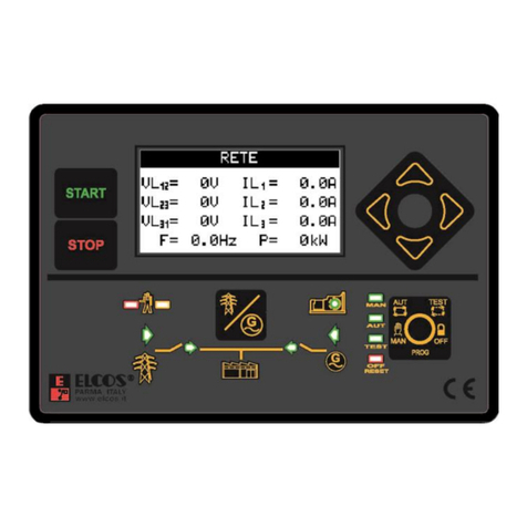
ELCOS
ELCOS CAM-335 User manual
ELCOS
ELCOS CEP-337 User manual
ELCOS
ELCOS CIM-131 Instruction Manual
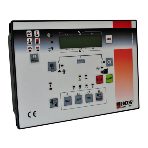
ELCOS
ELCOS CAM-685 User manual

ELCOS
ELCOS CIM-137/4G Instruction Manual
