ELCOS CIM-131 Instruction Manual

ELCOS SRL - Parma - CIM-131 - MAN - EN 1
CONTROL UNITS FOR IRRIGATION MOTOR PUMPS
AND PUMP WATER PRESSURE CONTROL
TYPE CIM-131
• Operates the engine accelerator to keep the pressure
of the system constant.
(accelerator with 2 wires connected to the control unit)
•Controlstheowofwaterinthepipe.
• Electronic pressure switch to control the pump water
pressure.
• Digital pump water pressure gauge.
• Clock for programming the starting and stopping of the
motor pump.
• Delayed acceleration after starting.
• Delayed deceleration before stopping.
• Assembly also on the machine and in the open air.
• CANBus SAE J1939 connection.
• Frost protection.
• Pressure boost function.
INSTRUCTION AND USER MANUAL
MADE TO:
PROTECT
motor pump sets by stopping them in the event
of:
- low oil pressure
- over-temperature
- belt breakage
- low coolant level
- low pump water pressure
- pump water overpressure
- overspeed
- A1
}
available
- A2
DISPLAY
on the panel the functions of:
- hour-meter
- oil pressure gauge
- water or oil thermometer
- tachometer
- pump water pressure gauge
- timer
- fuel level gauge
- battery voltmeter
- pump protection exclusion
- battery and oil lights
- protections intervention
- emergency stop

ELCOS SRL - Parma - CIM-131 - MAN - EN
2
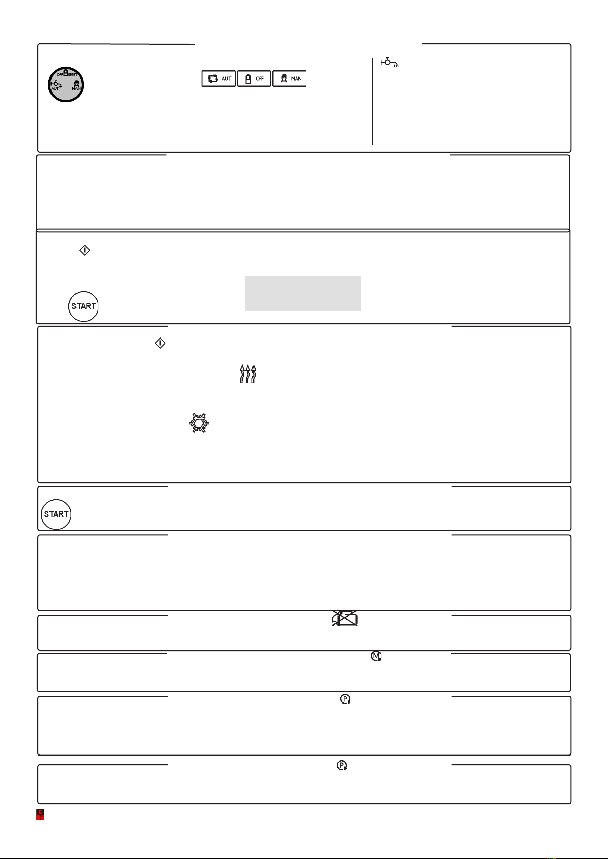
CLOCK
After starting, the motor pump protects itself automatically.
BRIEF INSTRUCTIONS
PUMP WATER
PRESSURE
IS DISPLAYED.
THE FUEL LEVEL
IS DISPLAYED.
THE VOLTMETER
OF THE BATTERY IS
DISPLAYED.
ACCUMULATED
OPERATION HOURS
ARE DISPLAYED.
PRESS TO ACCELERA-
TE THE MOTOR PUMP
WHEN THE CONTROL
UNIT IS IN MANUAL
MODE.
PRESS TO DECELERA-
TE THE MOTOR PUMP
WHEN THE CONTROL
UNIT IS IN MANUAL
MODE.
EMERGENCY STOP
PRESS TO ADJUST
ELECTRONIC PUMP
WATER PRESSURE
SWITCH.
THE BATTERY IS
NOT CHARGING.
LOW ENGINE
OIL PRESSURE
THE ENGINE PROTEC-
TION DEVICES ARE
ACTIVE. SWITCHED
ON 10 SEC. AFTER
DETECTION OF ENGINE
RUNNING.
STOPPING DUE TO
LOW COOLANT LEVEL.
STOPPING DUE TO
LACK OF BATTERY
CHARGING (BELT BRE-
AKAGE).
STOPPING DUE TO
HIGH ENGINE
TEMPERATURE.
PRESS IF YOU WANT
TO SET WORKING
TIME
(UP TO 96 HOURS).
CUMULATIVE ALARM
WITHOUT
STOP
WITH
STOP PRESS TO SELECT
THE FUNCTION:
AUTOMATIC
OFF/RESET
MANUAL
STOPPAGE DUE
TO LOW PRESSURE OR
PUMP WATER
OVERPRESSURE OR
ELECTRONIC
PRESSURE SWITCH
(TRANSMITTER) INTERRUPTED.
IN THIS CASE, THE ANOMALY IS
HIGHLIGHTED BY THE FLASHING
WARNING LIGHT.
STOPPING DUE TO LOW
FUEL LEVEL
STOPPING DUE TO
INSUFFICIENT
ENGINE OIL PRESSURE
PUMP PROTECTION
IS ACTIVE.
PRESS BRIEFLY,
THE LED STAYS
OFF, THE MOTOR
PUMP STOPS IF
THE CALL OR THE
TIMER ARE NOT
ACTIVE.
PRESS UNTIL THE
LED FLASHES,
THE MOTOR PUMP
STOPS AND STAR-
TING WITH THE
CALL AND THE TI-
MER IS SWITCHED
OFF.
NORMAL WORKING
PRESSURE. SWITCHED
OFF WHEN THE PRES-
SURE DIFFERS FROM
THE WORKING PRES-
SURE BY THE ALLOWED
OSCILLATION.
PRESS TO SELECT
THE DISPLAYED
FUNCTION, EACH
TIME IT IS PRESSED,
THE INSTRUMENT
INDICATED BY THE
DISPLAY CHANGES.
HOLD DOWN TO SI-
LENCE THE GENERAL
ALARM (BUZZER).
PRESS TO START
THE MOTOR
PUMP WHEN THE
CONTROL UNIT
IS IN MANUAL
MODE.
UTILIZE IN
PROGRAMMING.
PRESS UNTIL THE 2
SIGNS START
FLASHING
TO EXCLUDE PUMP
PROTECTION.
TO RE-ACTIVATE
PROTECTION, PRESS
AGAIN UNTIL THEY
SWITCH OFF.
MOTOR PUMP OPERA-
TING SPEED IS DISPLA-
YED.
ENGINE WATER OR OIL
TEMPERATURE IS
DISPLAYED.
ENGINE OIL
PRESSURE
IS DISPLAYED.
THE CALL IS
PRESENT.
THE ENGINE
IS RUNNING.
PUMP PRIMING
(ALWAYS ON)
FAILURE TO
PRIME PUMP
FLASHING.
CAN BUS PARAME-
TERS
OVERPRESS.
DISCONN’ED
LOW PRESS..

ELCOS SRL - Parma - CIM-131 - MAN - EN 3
CONTENTS
Brief instructions and contents page 2-3
Workingpressurecontrol-Pumpprotection-Failuretollpipes. “ 4
Operation: Functions selection-Glow plugs preheating-Starting with call-Starting with
start button-Starting-Starting failure-Detection of running engine-Automatic pump
priming-Pump priming failure.
“ 5
Operation: Clutch-Engine warming-Engine cooling-Stop-Emergency stop-Stop with the
Stop and Off-Reset buttons-Stopping failure-Buzzer.
“ 6
Operation: Timer-Resetting of the set time-Oil and battery warning lights-End of work-
Instruments-CAN Bus messages and instruments-Anomaly messages-CAN Bus instru-
ments- Cumulative alarms
“ 7
Engine and pump protection devices “ 8-9
Wiring diagram “ 10-11
Automatic pump priming connection “ 12
Notices “ 13
User programming “ 14
Dimensions - Technical data “ 15
Ordering data - Accessories supplied - Conformity declaration “ 16
STOP DUE TO INSUFFICIENT PRESSURE
OR
PUMP WATER OVERPRESSURE
STOPPING DUE TO LOW
COOLANT LEVEL.
ENGINE OVERSPEED
AND UNDERSPEED
FAULT
OVERPRESS.
LOW PRESS
ALARM DUE TO
STARTING
FAILURE.
STOPPING DUE
TO HIGH ENGINE
TEMPERATURE.
STOPPING DUE TO
INSUFFICIENT
ENGINE OIL
PRESSURE.
STOPPING DUE TO
LACK OF BATTERY
CHARGING (BELT
BREAKAGE).
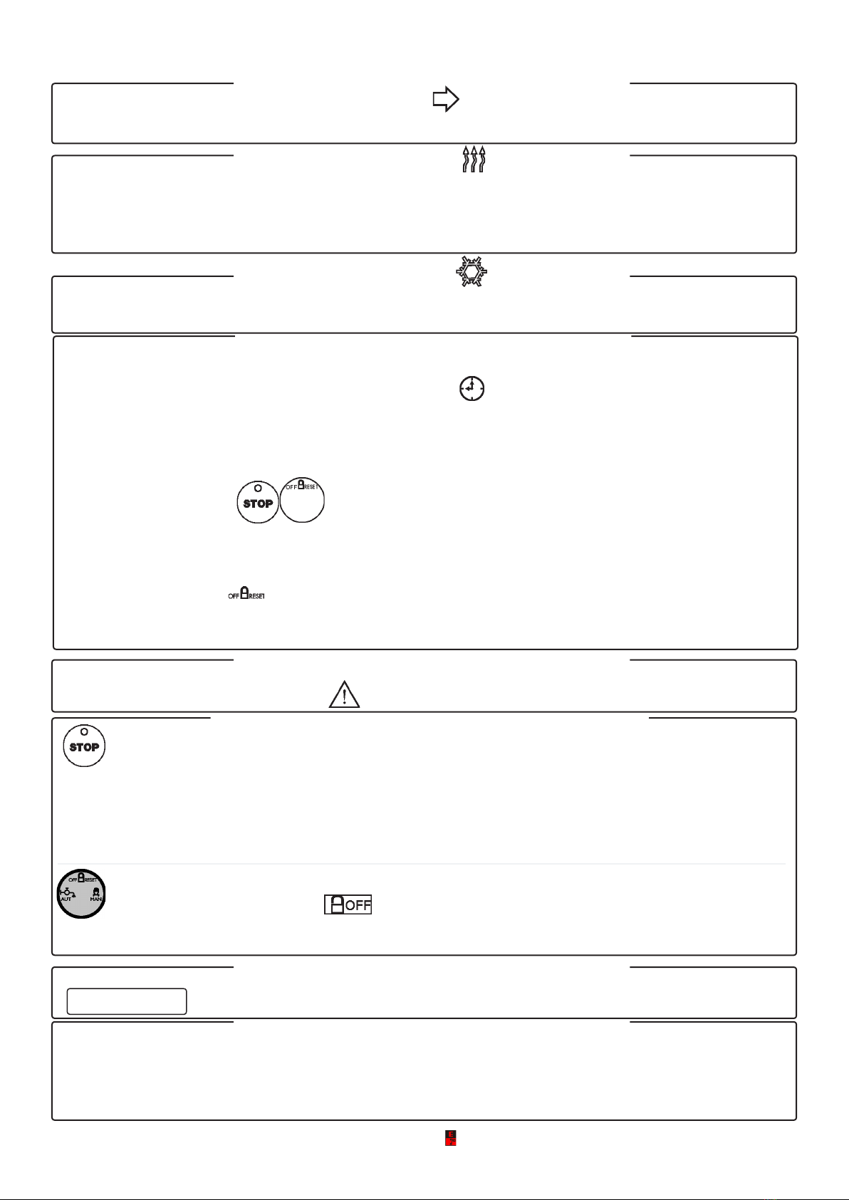
ENGINE WARMING
IN PROGRESS.
DECELERATION IN
PROGRESS.
ACCELERATION IN
PROGRESS.
CLUTCH ENGAGED
ENGINE COOLING IN
PROGRESS
ALARM OR STOP DUE TO:
• FUEL RESERVE
• NO FUEL.
PUSH-BUTTON PANEL LOCK see page 18.
UNDERSPEED
FAULT A1 - A2
OCCURRED
SWITCHING OFF OF PUMP PROTECTION DEVICES
Button switches off the pump protection devices:
• failure to prime main pump
•failuretollpipes
•insufcientpumpwaterpressure
• pump water overpressure
• abnormal acceleration
• adjustment error
- switching off is obtained by holding it down for at least 3 consecutive seconds; the function is indicated by the two intermittent
Indicators.
- this switching off is deleted by pressing the button again.

ELCOS SRL - Parma - CIM-131 - MAN - EN
4
Select the MANUAL operating mode, start the motor pump with button .
Set the required pressure with buttons after 10 seconds BAR STORED is displayed.
Waituntilthepipesarelledandthepressurehasstabilizedatthechosenvalue.Afternishingsetting,SELECTOPERATING
MODE , the pressure of the system will remain set at the chosen pressure.
The chosen pressure value can be corrected with the system under pressure, by pressing buttons .
The working pressure setting is deleted, when the engine is stopped by selecting operating mode .
SEQUENCE OF OPERATIONS
start up
running pump
PRIMING
IN PROGRESS
OVERPRESSURE remains set to two bars, this value is
added to the working pressure
(for example, working pressure 9 bars overpressure 11 bars)
Waituntilthepipesarelled.
When the working pressure has
stabilized, select .
The working pressure
is regulated automati-
cally.
Set the required
pressure.
Press to select the
pump water pressure
gauge.
example
Working
pressure
PUMP PROTECTION
NO ADJUSTING IS REQUIRED.
Pump water
overpressure
or
Insufcient
pressure
(subpressure)
INSUFFICIENT
PRESSURE
OVERPRESSURE
However it is possible to change the two bars of pressure
lowering (subpressure), by pressing button .
This change is deleted, when the engine is stopped, by selecting the
OFF/RESET operating mode.
WORKING PRESSURE
Press to
set the sub-
pressure value
(PRESSURE
SWITCH)
Press to select the
pump water pressure
gauge
FAILURE TO FILL PIPES FAULT
The acceleration starts with the engine running, with pump primed.
ThemotorpumpreachestheredenedWORKINGPRESSURE(see BARS STORED ) within the TIME OF FAILURE TO
FILL PIPES, set to 120 seconds. If air is present in the pipes, the acceleration will be alternated with pauses (of 15 seconds), if
the pressure remains steady for 5 seconds. This situation will be repeated several times until the WORKING PRESSURE is rea-
ched. If the pressure is not reached within the FAILURE TO FILL PIPES time (120 sec.), FAILURE TO FILL PIPES is displayed
on the display and the engine stops.
ABNORMAL ACCELERATION
(Pipe leakage controlled within the limits of the system).
As a result of a leakage, the engine tends to increase the revolutions to bring it back to WORKING PRESSURE. If the revolutions
increase by 10% for a time longer than 120 seconds, ABNORMAL ACCELERATION is displayed on the display and the engine
stops
WORKING PRESSURE CONTROL
9
9
PRESSOSTAT
BAR 6
Always on: pump primed.
Flashing: failure to prime.
The pump protection is enabled when warning lights PUMP PROTECTION ACTIVE and water pressure normal come on
after the water pressure has remained stable for 2 consecutive minutes, in any case 10 minutes after the engine started.
Intervention of the protection (5 seconds after the pressure goes up or down by two bars ) stops the engine and is
shown on the display:
Factory Setting
The motor pump starts up if
the motor pump is primed.
The priming probe senses
water presence (pump primed).
Select
MAN Automatic
pump
priming.
ELCOS SRL - Parma - CIM-131 - MAN - EN 5
T
HE STARTING OF THE MOTOR PUMP CAN BE OBTAINED IN THREE WAYS
:
• CALL
• TIMER The starting procedures are similar to each other.
•KEY
GLOW PLUGS PREHEATING
A
CTIVATED BEFORE STARTING
(GLOW PLUG
IS SHOWN ON THE DISPLAY
)
The duration of the preheating action can be set, the preheating action ceases before the beginning of the
starting process. The preheating control is disabled at the factory since it has been programmed to zero
seconds.
When the call contact closes and the DELAY AFTER CALL CLOSED has elapsed,
the control unit controls the glow plugs (if preset) and then the starting. If preset, the motor pump stays on
idle for the whole ENGINE WARMING , time, when this time has elapsed the motor pump reaches
and maintains the preset working pressure. When the call contact opens once the STOP DELAY after
CALL OPENING has elapsed, if preset the motor pump slowly decelerates, when the motor pump is on
idle the ENGINE COOLING time starts.
When this time has elapsed the motor pump stops. During its operation the motor pump is protected from
the faults controlled by the probes connected to the control unit.
STARTING WITH START BUTTON
Tostart,apulseonthebuttonissufcient.
Blocks the startup cycle if the pump has not started up after the fourth pulse.
It is obtained with measurement of the voltage and frequency of the battery charging alternator. Disables
the starter motor.
The priming pump starts; when the priming probe senses the presence of water, the pump stops and after
15 seconds the engine starting begins.
This takes place on closing of the CALL contact, or with Timer.
Before beginning the starting process, a buzzer is activated for 8 seconds, and after a 3-second pause the
starting process begins. To facilitate startup, a special circuit emits a series of four, 5-second pulses, with a
5-second delay between each pulse.
To activate the
control unit press
the button.
}
DETECTION OF ENGINE RUNNING
AUTOMATIC PUMP PRIMING (ALWAYS ON)
STARTING FAILURE
STARTING WITH CALL
The priming probe does not sense the presence of water and a time higher than 240 seconds has
elapsed.
PUMP PRIMING FAILURE (FLASHING)
OPERATION
FUNCTIONS SELECTION
The function selected with the key is
shown by the associated warning light.
•AUT Automatic pressure control.
•OFF The engine cannot be started and if
running it is stopped.
•MAN Operation without automatic
pressure control.
Factory Setting
The motor pump starts up if
the motor pump is primed.
ELCOS SRL - Parma - CIM-131 - MAN - EN
6
The control unit has its own buzzer. Before starting automatically the motor pump activates
the buzzer intermittently for 8 seconds, followed by a pause of 3 seconds (this function can be
switched off). This buzzer also operates for the intervention of the protection devices listed on
page 8-9. It is possible to place a buzzer externally to be connected to the relevant output.
• On pressing briefly, the led stays off, the motor pump stops if the call or the timer are not
active.
• On pressing (3 seconds) until the LED flashes, the motor pump stops and starting by call and
by timer are disabled, with the engine stopped the warning light remains flashing. The deletion of
this switching off occurs on pressing the stop button (3 seconds) until the flashing warning light
goes out.
Press until switching on of .
The engine cannot be started in any way and if it is running it is stopped. Reactivates the protec-
tion devices and all the locked functions.
Stopping is obtained:
• Through intervention of the protection devices.
• Through end of work of the clock and of the timer .
• By pressing the emergency button (to be fitted externally).
• On opening of the call contact.
• At end of work through intervention of the underspeed or the flow switch.
.
• On pressing buttons , the engine stops after slow deceleration.
Stopping can be obtained in two ways:
• With electromagnet de-energized with engine running and energized with it stopped, remaining
in this condition for 15 sec. after detection of engine stopped.
On pressing button the stopping electromagnet stays energized for 60 seconds.
• With electromagnet or electro-valve activated while the engine is running and deactivated
when stopped. This condition is maintained even when the engine is stationary.
OPERATION
CLUTCH
ENGINE WARMING
(factory-excluded)
EMERGENCY STOP
STOPPING FAILURE
BUZZER
ENGINE COOLING
STOP
This is engaged on reaching a certain engine speed. This clutch disengages when the engine
speed drops below the set value.
After closing of the call contact or TIMER or SMS pump priming takes place, the engine stays on
idle for the time necessary to allow warming of the engine. After this time has elapsed the engine
slowly reaches the working pressure. During heating the protection devices are active.
This intervenes if the running engine signal is detected 60 seconds after the stop command.
STOPPING FAILURE will be read on the display.
On opening of the call contact or TIMER the engine slowly decelerates. When
the engine is on idle the COOLING TIME starts, and after this time has elapsed the engine stops.
This can be obtained in any operating condition, by installing one or more (latching) buttons. This
is indicated by the optical indicator .
STOPPING WITH THE STOP AND OFF-RESET BUTTONS

ELCOS SRL - Parma - CIM-131 - MAN - EN 7
MESSAGES AND CAN Bus INSTRUMENTS
Sent (SAE J1939 protocol Bus) from the engine equipped with control unit for electronic control
of the injection system.
ANOMALY MESSAGES
The anomaly messages managed by the injection control unit are indicated on the display
example
SPN 1234-12 CAN Bus.
Problems of connection ANOMALY CAN Bus to the CAN Bus.
CAN Bus INSTRUMENTS
TACHOMETER - OIL PRESSURE GAUGE - THERMOMETER
The control unit incorporates seven instruments that can be selected in sequence by pressing button .
HOUR-METER - total hours of operation witht he engine running the signal pulsates, to indicate the
correct functioning of the HOUR-METER).
PRESSURE GAUGE - Engine oil pressure
THERMOMETER - Engine oil and water temperature
TACHOMETER - Speed of motor pump
PRESSURE GAUGE - Engine water pressure
INDICATOR - Fuel level percentage
VOLTMETER - Battery voltage
OPERATION
TIMER
OIL AND BATTERY WARNING LIGHTS
CUMULATIVE ALAR
INSTRUMENTS
END OF WORK
(Flow stopped)
Always enabled, allows if necessary the motor pump to be operated for a settable time (maximum 96 hours), at the
end of which it is stopped and on the display the end of work time indicator comes on.
The work time is set by pressing the push-button ( lights up) until the desired value appears on the
DISPLAY .
On releasing the push-button, the timer automatically starts working, continously displaying the remaining work time
.
CANCELLING THE SET TIME
To zeroing the set time, tkeep the push-button pressed until it reaches zero.
Switched on with the automatic or manual function these switch off with the engine running with oil pressure
and battery recharging system normal. Control unit in Stand by, warning light pulses .
When the engine revolutions fall by 10% and the WORKING PRESSURE stays constant for 120 seconds END OF
WORK is displayed on the display and the engine stops.
Ifthereisnotthiscondition,aowswitchmustbeinstalled(Endofworkwithowswitchseeonpage9).
LED (red) STEADY LIGHT: anomaly managed by the injection control unit will cause the engine to stop.
LED (red) FLASHING LIGHT: anomaly managed by the control unit CIM-131 will cause the engine to stop.
LED (yellow) STEADY LIGHT: anomaly managed by the injection control unit will NOT cause the engine to
stop.
LED (yellow) FLASHING LIGHT: anomaly managed by the control unit CIM-131 will NOT cause the engine
to stop, or indicates a preventive maintenance operation.
LED OFF ALL OK.
}
TRANSMITTERS MOUNTED ON THE ENGINE
ON REQUEST

ELCOS SRL - Parma - CIM-131 - MAN - EN
8
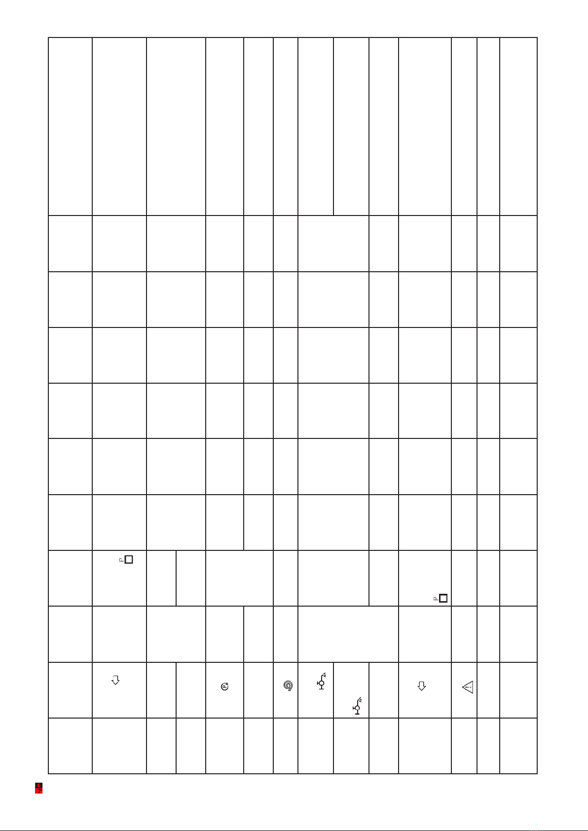
ENGINE AND PUMP PROTECTION DEVICES
The ENGINE PROTECTION DEVICES are enabled when indicator comes on (10 seconds after detection of engine running ). The PUMP PROTECTION is enabled when
comesonafter2consecutiveminutesofsufcientwaterpressure,indicatedbyNORMALPRESSUREindicator and in any case 10 minutes after the pump started. Intervention
due to a fault enables the GENERAL ALARM.
DESCRIP-
TION OF
FAULTS OR
FUNCTIONS
INDICATION
ON THE
FRONT PANEL
MOTOR PUMP
PROBE
INSTANT OF
ACTIVATION
(seconds)
INTERVEN-
TION DELAY
(seconds)
PRO-
GRAMMED
THRESHOLD
(FACTORY
SETTING)
STORES THE
FUNCTION
DECELE-
RATION
ENGINE
COOLING
STOP INTERVENTION OCCURS WHEN:
BATTERY
UNDER-
VOLTAGE
BATTERY
UNDER-VOL-
TAGE
BATTERY Always active
2
11 (12V)
22 (24V) NOT = NOT
DOES
NOT STOP
Battery voltage remains lower than the program-
med threshold for the whole of the intervention
delay time.
BATTERY
OVER-
VOLTAGE
BATTERY
OVER-
VOLTAGE 5
16 (12V)
32 (24V) YES SLOW NOT Battery voltage exceeds the programmed threshold
for the whole of the intervention time.
OVER-
HEATING
DETECTED BY
THERMOSTA-
TIC SWITCH
OVER-
HEATING THERMOSTA-
TIC SWITCH
With running
engine 2 = YES SLOW YES WITH
STOP
The temperature detected by the transmitter
exceeds the set threshold.
FUEL
RESERVE FUEL
RESERVE
Flashing
FUEL
FLOAT
TERMINAL T
Always active
5 10% NOT = NOT DOES
NOT STOP
The fuel level remains lower than the threshold for
the whole of the intervention delay time.
NO FUEL
NO FUEL
Always
on
FUEL
FLOAT
TERMINAL W
5 1% YES SLOW YES WITH
STOP
LOW OIL
PRESSURE
LOW OIL
PRESSURE OIL PRESS-
URE SWITCH
10 after detec-
tion of running
engine
2 = YES QUICK NOT WITH
STOP
The pressure is lower than the threshold set by the
pressure switch.
STOPPING
FAILURE
STOPPING
FAILURE
ELECTRO-
VALVE OR
ELECTRO-
MAGNET
After the stop
command 60 = YES = NOT DOES
NOT STOP
The engine running signal is detected after the
stop command and the intervention delay time has
elapsed.
LOW
RADIATOR
FLUID
LEVEL
LOW
RADIATOR
LEVEL
LEVEL
PROBE Always active 5 = YES SLOW NOT WITH
STOP
The coolant falls below the electrode and the inter-
vention delay has elapsed.
CHARGING
ALTERNATOR
FAULT (BELT
BREAKAGE)
CHARGING
ALTERNATOR
FAULT ALTERNATOR
10 after detec-
tion of running
engine
5 = YES SLOW NOT WITH
STOP
Alternator does not recharge the battery and the
intervention delay time has elapsed.
STARTING
FAILURE
STARTING
FAILURE
BATTERY
-Starting
Motor
Always active = = YES QUICK NOT WITH
STOP
The whole series of starting attempts is unable to
start the engine.
ELCOS SRL - Parma - CIM-131 - MAN - EN 9
DESCRIP-
TION OF
FAULTS OR
FUNCTIONS
INDICATION
ON THE
FRONT PANEL
MOTOR PUMP
PROBE
INSTANT OF
ACTIVATION
(seconds)
INTERVEN-
TION DELAY
(seconds)
PROGRAM-
MED
THRESHOLD
(FACTORY
SETTING)
STORES THE
FUNCTION
DECELE-
RATION
ENGINE
COOLING
STOP INTERVENTION OCCURS WHEN:
THE END
OF WORK
FUNCTION
DUE TO FLOW
SWITCH IN-
TERVENTION
END OF
WORK FLOW
SWITCH
FLOW
SWITCH
When the
pump protec-
tion active
warning light
comes on
20 = NOT SLOW YES WITH
STOP
Thereisnowaterowandtheinterventiondelayhas
elapsed.
AVAILABLE
FAULT INPUT
A1
A1
=
Always active
5 = YES SLOW YES WITH
STOP
The input is negative (-) and the intervention delay has
elapsed.
AVAILABLE
FAULT INPUT
A2
A2 With running
engine
FAILURE TO
PRIME MAIN
PUMP
FAILURE TO
PRIME
(ashing)
PUMP PRI-
MING LEVEL
PROBE
With running
engine
240 =
YES =NOT WITH
STOP
The priming probe does not sense water presence and
the intervention delay has elapsed.
FAILURE TO
FILL PIPES
FAILURE TO
FILL
ELECTRONIC
PRESSURE
SWITCH
120 =YES SLOW NOT WITH
STOP
The working pressure is not reached and the interven-
tion delay has elapsed.
OVERSPEED OVER-
SPEED
ALTERNATOR
TERMINAL W Always active 24000 RPM YES = NOT WITH
STOP
The speed remains higher than the programmed thresh-
old for the entire duration of the intervention delay.
INSUFFICIENT
PUMP WATER
PRESSURE
INSUFFICIENT
WATER PRES-
SURE
ELECTRONIC
PRESSURE
SWITCH
After detection
of working
pressure and in
any case 600”
after the pump
started
5 = YES SLOW YES WITH
STOP
The pump water pressure remains lower for the entire
duration of the intervention delay.
PUMP WATER
OVERPRES-
SURE
PUMP OVER-
PRESSURE The pump water pressure remains higher for the entire
duration of the intervention delay.
ABNORMAL
ACCELER-
ATION
ABNORMAL
ACCELER-
ATION
With running
engine 60
Allowed accel-
eration percen-
tage 20%
YES SLOW NOT WITH
STOP
The speed remains higher than the programmed thresh-
old for the entire duration of the intervention delay.
END OF
WORK DUE
TO UNDER-
SPEED INTER-
VENTION
UNDERSPEED
END OF
WORK
ALTERNATOR
TERMINAL W
When the
pump protec-
tion active
warning light
comes on.
120
Allowed
deceleration
percentage
10%
NOT SLOW YES WITH
STOP
The speed drops below the programmed threshold and
the working pressure remains constant for the entire
duration of the intervention delay.
EMERGENCY
STOP
EMERGENCY
STOP
EMERGENCY
BUTTON Always active = = YES = NOT WITH
STOP Emergency button is pressed.
ADJUSTMENT
ERROR
ADJUSTMENT
ERROR
ALTERNATOR
TERMINAL W
With running
engine 120 = YES = NOT WITH
STOP
The rotation speed of the engine has not changed after
120 seconds.
PUMP WATER
PRESSURE
TRANSMIT-
TER
TPA
DISCON-
NECTED
ELECTRONIC
PRESSURE
SWITCH
ALWAYS
ACTIVE 60 = YES SLOW NOT WITH
STOP The pressure transmitter circuit is disconnected.

ELCOS SRL - Parma - CIM-131 - MAN - EN
10
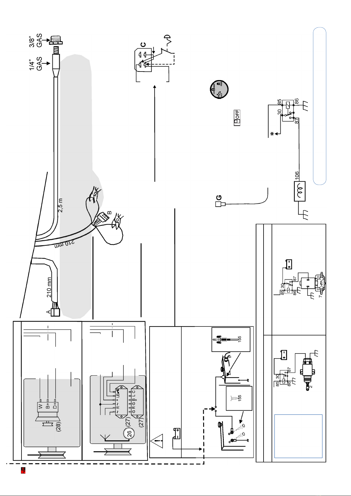
CAN BE USED FOR
AUXILIARIES
WHITE/RED
BROWN (Only for permanent magnets)
RED
BATTERY
GREY
WIRING DIAGRAM
GREEN
WHITE
YELLOW
ORANGE
BLACK
BLACK/BLUE
ORANGE/BROWN
WHITE/VIOLET
LIGHT BLUE
WHITE/GREEN
YELLOW/ORANGE RED/GREEN
BROWN/BLUE
WHITE/YELLOW
BROWN/RED
BROWN/GREEN
STOP
SYSTEMS
SEE PAGE 11
ORANGE/BLUE
INDICA-
TOR
WRESERVE
ACCELERATOR
YELLOW GREEN
CABLE 1,5m
FUSE
YELLOW/BLUE
WHITE/RED
GREEN
BROWN (Only for permanent magnets)
WHITE
YELLOW
GREY
RED/GREEN
BROWN/BLUE
BLACK/
GREEN
GREY
YELLOW/ORANGE
ORANGE
BLACK
RED
BATTERY
STOP
SYSTEMS
SEE PAGE 11
YELLOW GREEN
BLACK/BLUE
ORANGE/BROWN
WHITE/VIOLET
TO THE GLOW
PLUG RELAY
ORANGE/BLUE
INDICA-
TOR
WRESERVE
ACCELERATOR
FUSE
USED ONLY FOR AUTO-
MATIC PUMP PRIMING
see page 12.
CAREFULLY INSULATE ANY WIRES THAT
ARE NOT CONNECTED, INSERTING THE
BATTERY CUT OUT SWITCH
THE CONTROL UNIT IS IN OFF MODE. TO
ENABLE THE OTHER FUNCTIONS PRESS
THE RELEVANT BUTTON .
CABLE 2,5m
LIGHT BLUE
GREY
WHITE/YELLOW
BROWN/RED
BROWN/GREEN
WHITE/GREEN
YELLOW/BLUE
CALL
10m MAX
VIOLET
PUMP
CLUTCH
SELF-
PROPELLED
IRRIGATOR
SELF-
PROPELLED
IRRIGATOR
SELF-
PROPELLED
IRRIGATOR
GREY
OPERATES
ON
CLOSING
OF THE
CONTACT
FLOW SWITCH
installation
The straight pipe
must be 5 times
the diameter of the
pipe. The direction
oftheowswitch
must match the
arrow on the cover.
INSTALL THE FLOW SWITCH
ON THE INTAKE.
Use the highest possible
number of paddles.
FUSES
F1 25A POSITIVE POWER SUPPLY TO
ENGINE CONTROL UNIT.
F2 3A POSITIVE POWER SUPPLY TO
ENGINE CONTROL UNIT.
F3 7,5A POWER SUPPLY TO CIM CONTROL
UNIT...
TO CHANGE THE FUSES,REMOVE THE
RELEVANT COVER OF THE CONTROL UNIT
ELCOS SRL - Parma - CIM-131 - MAN - EN 11
PUMP WATER PRESSURE TRANSMITTER CABLE
STOP SYSTEMS SET UP
To stop with the SOLENOID VALVE
cut and isolate the BLUE/BROWN lead
ELIMINATE THE BRIDGE WHEN CON-
NECTING THE EMERGENCY BUTTON
EMERGENCY STOP
THIS CAN BE OBTAINED WITH A
LATCHING BUTTON. ON RELEASING
THE EMERGENCY BUTTON, STAR-
TING OR MOTION OF THE ENGINE
IS STOPPED. TO RESET, RELEASE
THE BUTTON, PRESS .
AND SELECT
ORANGE/VIOLET
GLOW PLUG
RELAY
EMERGENCY
BUTTON
The control unit has
been designed to
control stopping with
an ELECTROMAGNET
SET UP
• WATER OR OIL
THERMOMETER
• OIL PRESSURE GAUGE
To view the water/oil THERMOMETER and the
oil PRESSURE GAUGE, connect the
transmitters to the respective wires of the unit,
then CUT and isolate the BLACK/VIOLET wire.
WARNING! :
IT IS NOT
POSSIBLE
TO MOUNT THE
EMERGENCY
STOP BUTTON ON
A STOP SYSTEM
WITH ELECTRO-
MAGNETS ELECTROMAGNET to
activate the engine STOP lever.
SOLENOID
to close
the fuel
YELLOW
YELLOW
EXCITED IN STOP MODE EXCITED WHILE RUNNING
STOP SYSTEMS
ROD
ELECTRODE
SCREW
ELECTRODES
COOLANT LEVEL PROBE
FOR RADIATORS WITH
PLASTIC EXPANSION TANK
FOR RADIATORS WITH
METAL EXPANSION TANK
IF THE FUNCTION- LOW COO-
LING LIQUID LEVEL
IS NOT USED CONNECT
YELLOW/ORANGE WIRE
TO EARTH
PERMANENT MAGNETS
YELLOW
YELLOW
RED
BROWN
GREEN
+ BATTERY
WHITE/RED
DO NOT USE
PRE-EXCITATION
WHITE/RED
+ BATTERyY
GREEN
BROWN
CHARGE ALTERNATOR:
BROWN
BLUE/BROWN
BLACK/VIOLET
BLACK
SETTING THE TACHOMETER see page 14

ELCOS SRL - Parma - CIM-131 - MAN - EN
12
AUTOMATIC PUMP PRIMING CONNECTIONS
ACCESSORIES
ON REQUEST
(2/7) ELECTROMAGNET OR ELECTRO-VALVE
(3) OIL PRESSURE SWITCH
(4) THERMOSTATIC SWITCH
(18) FUEL FLOAT FOR INDICATOR AND RESERVE
(97) OIL PRESSURE TRANSMITTER
(102) WATER FLOW SWITCH
(112) TEMPERATURE TRANSMITTER
(155) RADIATOR LIQUID LEVEL PROBE
(163) SPEED VARIATOR
(173) PUMP WATER PRESSURE TRANSMITTER
(SUPPLIED)
PRIMING PROBE
EXCLUSION
connect to ground the
BROWN/BLUE wire.
SELF-
PROPELLED
IRRIGATOR
SELF-
PROPELLED
IRRIGATOR
SELF-
PROPELLED
IRRIGATOR
OPERATION
AUTOMATIC PRIMING
The priming pump (P2) starts,
when the water reaches the priming
probe, lthe pump stops.
PRIMING FAILURE
The pump is stopped if the priming
probe does not sense the presence
of water within 240 sec..
To connect
PUMP PRIMING, remove
the male connector,
insert the connector with
the wires brown/blue
yellow/blue.
GREY
CABLES
2,5 m
Manual
priming
BROWN/GREEN
WHITE/YELLOW
YELLOW/BLUE
BROWN/RED
BROWN/BLUE
BROWN/BLUE
YELLOW/BLUE
FEMALE
CONNECTOR
PRIMING
PROBE
Male
connector
CLUTCH
WHITE/YELLOW
(26) PERMANENT MAGNETS CHARGE ALTERNATOR
(27) ALTERNATOR REGULATOR
(28) PRE-EXCITATION CHARGE ALTERNATOR
(40) STARTING MOTOR
(41) BATTERY
(106) GLOW PLUGS
(157) VISUAL INDICATOR (GENERAL ALARM)
(191) A1 AVAILABLE FOR PROTECTION PROBE
(192) A2 AVAILABLE FOR PROTECTION PROBE
(207) PRIMING PUMP
(212) NON-RETURN PRIMING VALVE.

ELCOS SRL - Parma - CIM-131 - MAN - EN 13
YOUR ELECTRICAL TECHNICIAN CAN ASK US ANYTHING ABOUT THIS CONTROL
UNIT BY TELEPHONING ONE OF OUR TECHNICIANS
Only for starting and surveillance of the diesel motor pump and stops it if there are anomalies in
the parts controlled by probes.
It has been designed to be installed also on the machine.
Warning:
adhere closely to the following advice
- Connect always following the wiring diagram shown on page 10-11.
- Each technical operation must take place on the motor pump unit with the engine stopped and
with terminal 50 of the starter motor disconnected.
- Check that the line loading and the consumption of the connected equipment are compatible
with the described technical characteristics.
- Install in such a way that there is always adequate heat disposal.
- Always install under other equipment which produces or spreads heat.
- Make sure that no copper conductor cuttings or other waste material fall inside the control unit.
- Never disconnect the battery terminals with the engine running.
- Never use a battery charger for the emergency start-up, this could damage the control unit.
- To protect the safety of persons and the equipment, before connecting an external battery
charger, disconnect the electrical plant terminals from the battery poles.
THIS CONTROL UNIT IS NOT SUITABLE FOR OPERATING IN THE FOLLOWING
CONDITIONS:
- Where the environmental temperature is outside the limits indicated in the Technical Data.
- Where the air pressure and temperature variations are so rapid as to produce
exceptional condensation.
- Where there are high levels of pollution caused by dust, smoke, vapour, salts and
corrosive or radioactive particles.
- Where there are high levels or heat from radiation caused by the sun, ovens or the like.
- Where attacks from mould or small animals are possible.
- Wherethereistheriskofreorexplosions.
- Where the control unit can receive strong vibrations or knocks.
ELECTROMAGNETIC COMPATIBILITY
This control unit functions correctly only if inserted in plants which conform with the CE marking
standards; it meets the exemption requirements of the standard EN61326-1 but it cannot be
excluded that malfunctions could occur in extreme cases due to particular situations.
The installer has the task of checking that the disturbance levels are within the requirements of
the standards.
CONDUCTION AND MAINTENANCE
The following maintenance operations should be performed every week:
- check that the indicators function;
- check the batteries;
- check that the conductors are tight, check the condition of the terminals.
UNLESS WE MAKE A WRITTEN DECLARATION STATING THE CONTRARY, THIS CONTROL
UNIT IS NOT SUITABLE FOR USE AS A CRITICAL COMPONENT IN EQUIPMENT OR PLANTS
RESPONSIBLE FOR KEEPING PERSONS OR OTHER LIVING BEINGS ALIVE.
NOTICES

ELCOS SRL - Parma - CIM-131 - MAN - EN
14
TACHOMETER ADJUSTMENT WITH CHARGING ALTERNATOR FREQUENCY W.
Press until
the LED
comes on.
(CALIBRATION
RPM)
EXIT FROM
PROGRAMMING MODE.
Press until
the LED
goes out.
LANGUAGE
TACHOMETER
SETTING
USER
PROGRAMMING
TIMER
BUTTON LOCK
_ _ _ _
RPM
3000 RPM
ADJUSTMENT
IN PROGRESS OK
3000 RPM
CLOCK SETTING
TIMER Allows up to 10 starts/stops to be programmed over
a period of 24 hours. This programming stops the TIMER
function.
1 0 : 2 1
CLOCK
Decreases Increases
LANGUAGE CHOICE. The language set up is ITALIAN; the languages that can be selected are: ENGLISH - FRENCH - GERMAN
- SPANISH - PORTUGUESE.
BUTTON LOCK. With the push-button panel locked, buttons
remain active.
LANGUAGE
00:00 09:15 09:15
00:00 10:22 10:22
LOCKED BUTTON RELEASED
START 1 :START 1 OK
STOP 1 OK
LOCKED
RELEASED
ENGLISH
Language choice:
Italian German
English Spanish
French Portuguese
Press to select the language.
Press to choice
Set hours and minutes
Decreases Increases
Set hours and minutes
Decreases Increases
Decreases Increases
Set the engine revolutions read
on the portable tachometer.
Press and wait for
OK to be written.
Press and wait for
OK to be written.
Press and wait for OK to be written.
Aftertherstprogrammingsettinghas
beennishedtheother9programming
settings can be repeated,
by pressing .
Press and wait for
OK to be written.
Press and wait for
OK to be written.
Press to
display.
Press to
display.
Press to
select
START 1
2
-
-
-
10
To stop exit the
programming mode and
press stop
CLOCK allows up to 10 STARTS/STOPS to be programmed over a period of 24 hours. Carry out setting operations with the
engine stopped. The control unit accepts only complete programming settings: START 1 STOP 1
START 2 STOP 2 and so on
If a start is programmed, but a stop is not programmed,
ERROR is written on the display. While running with the engine started by clock, indicator stays on.
During stopping by clock, indicator comes on and stays on until the next start.
_ _ _ _
Setting
set to zero.
USER PROGRAMMING
NECESSARY PROGRAMMING
When the white/red wire is connected.
Factory setting
RPM/W CALIBRATION PRESS START
Start the primed motor pump
with delivery
closed
with button .
TACHOMETER ADJUSTMENTS
Bring the engine to idle at constant known
speed for example via a portable tachometer.
ELCOS SRL - Parma - CIM-131 - MAN - EN 15
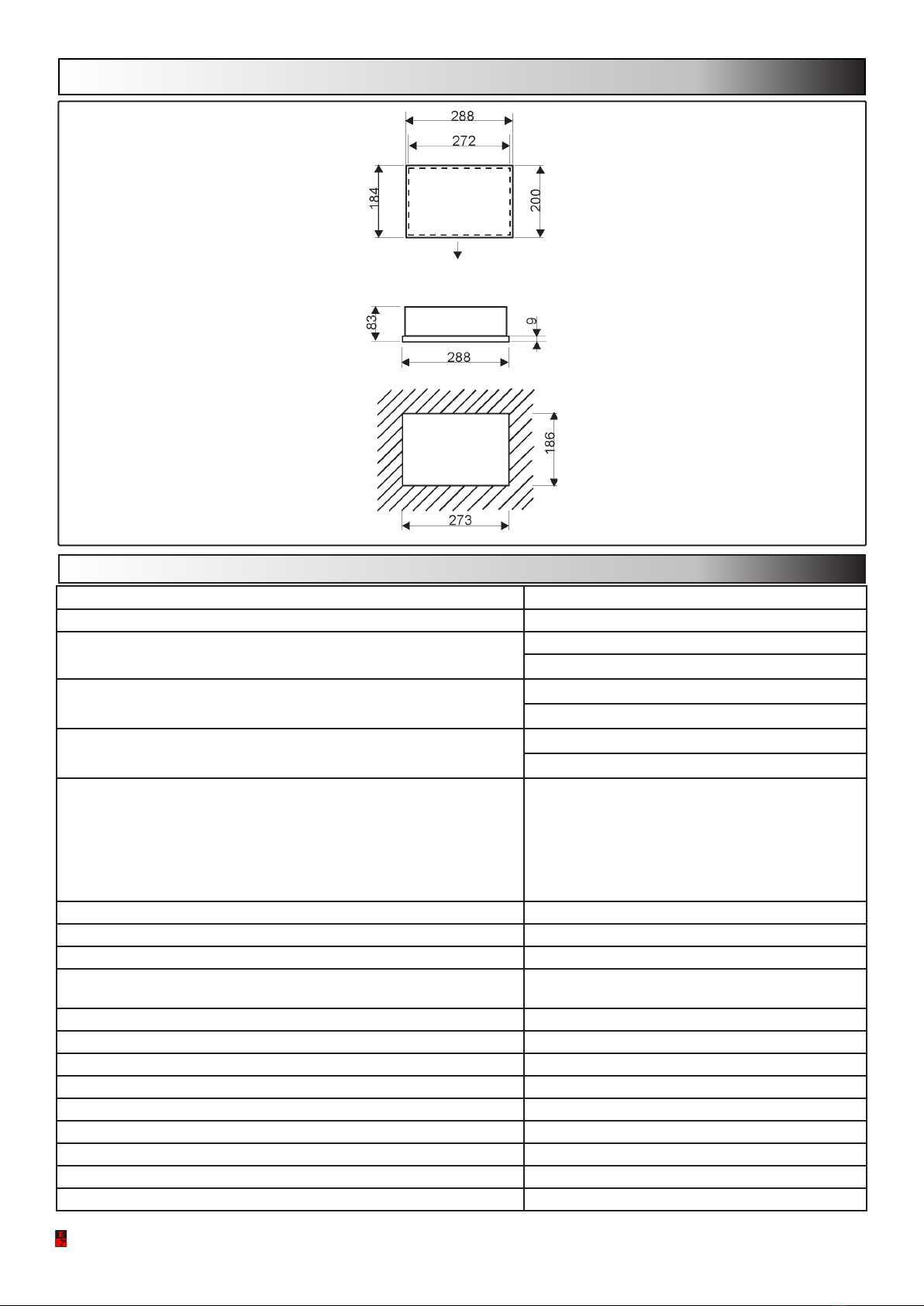
DIMENSIONS
Connectors output
see page 10-11
PANEL
HOLE
TECHNICAL DATA
Battery power supply 12 Vdc 24 Vdc
Supply voltage 8÷ 32V
Consumption in standby 3.5mA at 12V
2.5mA at 24V
Consumption with engine stationary 250mA at 12V
150mA at 24V
Max. Consumption 850mA at 12V
550mA at 24V
Max load of the output:
• (stopping) yellow
• (starting motor) black
• (general alarm) red/green
• (auxiliary) brown
• priming pump yellow/blue
• pump clutch white/yellow
3A
40A
3A
3A
3A
3A
Temperature range -10 ÷ +60 °C
Hour-meter 4 digits
Engine oil pressure gauge 0 ÷ 9 bar
Pump water pressure transmitter:
• allowed max. pressure 21 bar
Engine water and oil thermometers +20 ÷ +145°C
Tachometer 4000 rpm
Timer 1’ ÷ 24 h
Serial communication parameters 9600 baud, 8 bit data,1 bit stop, even parity
Rechargeable batteries 2x1,2V type AAA
Installation conditions for external use
Degree of protection box/connector IP54/IP20
Control unit weight 2,2 kg
Weight with control unit mounted on the support 4,6 kg

ELCOS SRL - Parma - CIM-131 - MAN - EN
16
ACCESSORIES ON REQUEST
Type Code
- Support KIT CRU-CIM 40493383
- Speed variator VAR-140 12V 00571543
- Flow switch FAP-100 00500312
ORDERING DATA ACCESSORIES SUPPLIED
Type CIM-131 Codice 00211101
- PRE-WIRED CONNECTOR CIM-130/1/6/7
CODE 70804397
- PUMP WATER PRESSURE
TRANSMITTER TYPE TPA-200 “ 70500255
- NIPPLE F1/4” GAS -M3/8”GAS “ 70190241
- NUTS KIT “ 40179906
support on request
BASE FITTING
Table of contents
Other ELCOS Control Unit manuals

ELCOS
ELCOS CIM-130 Instruction Manual

ELCOS
ELCOS CAM-432 Instruction Manual

ELCOS
ELCOS CAM-685 User manual

ELCOS
ELCOS CIM-137 Instruction Manual

ELCOS
ELCOS CEP-337 User manual

ELCOS
ELCOS CEP-090 User manual

ELCOS
ELCOS CAM 684 User manual

ELCOS
ELCOS DCA-110 User manual

ELCOS
ELCOS DCA-120/10 Owner's manual

ELCOS
ELCOS CIM-137/4G Instruction Manual


Popular Control Unit manuals by other brands

Wheelock
Wheelock ZC-9 installation instructions

Emerson
Emerson EX4 operating instructions

Honeywell
Honeywell VR4920Z 1000 instruction sheet

Wilo
Wilo JetValve Installation and operating instructions

Moxa Technologies
Moxa Technologies WAPN008 user manual

GAMA Electronics
GAMA Electronics PB3-DRC instruction manual


