ELCOS CAM-335 User manual
GENSET CONTROL UNIT
CAM-335
Developed to equip automatic emergency panels.
It controls and operates genset, connecting the power user to the mains or generator.
USER’S MANUAL
Functions:
Complete with backlit graphic display with touch
screen to view:
Three voltmeters for the mains.
Three voltmeters for the generator.
Three mains/generator ammeters.
Mains/generator frequency meter.
Generator tachometer.
Mains/generator kW (active), kVAR (reactive)
and kVA (apparent) powers.
Battery voltmeter.
Fuel level gauge.
Water/oil thermometer.
Oil pressure gauge.
Total hour-meter.
Partial hour-meter.
Start-ups counter.
Automatic monitoring of faults with display messages.
Complete three-phase voltmetric control of mains and genset (undervoltage, overvoltage, phase asymmetry,
incorrect phase sequence, underfrequency and overfrequency).
Texts in 7 languages: Italian, English, French, German, Spanish, Portuguese and a programmable language.
CAN Bus Connection SAEJ1939.
RS232, RS485 serial ports and USB.
MOD Bus RTU Protocol.
4-maintenance management.
Management of rental hours.
Remote controls (start, stop, EJP).
Generator start and stop on power demand.
Ability to start generator when the battery charge is low.
Option of associating inputs and outputs with different functions.
Glow plug preheating management.
Management of refuelling of working tank from storage tank.
Clock for programming genset starting or stopping.
Automatic test.
Anomaly log.
Option of password protected programming.
Dimensions (LxHxW) 157x109x74mm

________________________________________________________________________________________________________
ELCOS –Parma –Italy –CAM-335 Valid for firmware revision 1.14 and above Page 2 of 20
TABLE OF CONTENTS
CHRONOLOGY OF MANUAL REVISIONS.........................................................................2
INSTRUCTIONS IN BRIEF..................................................................................................3
INSTRUMENTS...................................................................................................................3
DISPLAY..............................................................................................................................4
OPERATION........................................................................................................................6
CONNECTION DIAGRAM.................................................................................................12
USER PROGRAMMING....................................................................................................14
FAULT LIST.......................................................................................................................17
TECHNICAL SPECIFICATIONS........................................................................................18
WARNING..........................................................................................................................19
INFORMATION FOR ORDERING.....................................................................................20
STANDARD ACCESSORIES ............................................................................................20
ACCESSORIES AVAILABLE ON REQUEST....................................................................20
DOCUMENTATION ON REQUEST ..................................................................................20
DECLARATION OF CONFORMITY....................... Provided in the manual as an attachment
CHRONOLOGY OF MANUAL REVISIONS
Date
Revision
Description
Page
27/07/2015
1.00
First release
05/09/2016
1.05
MAX mains voltage present delay =9999 sec.
12 technical prog.
10/10/2016
1.06
Fault: radiator stops without cooling
8 technical prog.
19/12/2016
1.09
Semi-automatic mode, reset of maintenance cycle, acceptance
of commands via SMS from any telephone number.
6, 16, 18 technical
prog.
23/05/2017
1.10
Exclusion of current transformers
Programming of maximum number of fault SMS
messages
Keyboard error input
Programmable mains contactor fault input
Programmable genset contactor fault input
5,12,18, 20
Technical prog.
1.13
Change automatic test
1, 7, 3, 13
Technical prog.
04/06/2020
1.14
Time synchronization of other control units.

________________________________________________________________________________________________________
ELCOS –Parma –Italy –CAM-335 Valid for firmware revision 1.14 and above Page 3 of 20
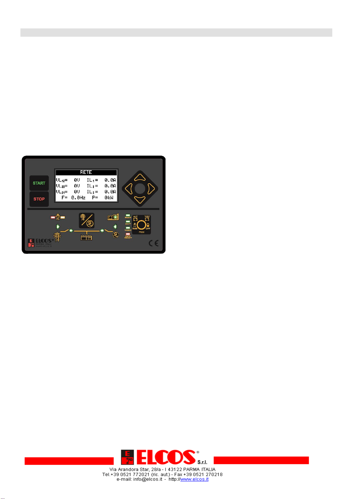
INSTRUCTIONS IN BRIEF
INSTRUMENTS
The control unit has a backlit 128 x 64 dot graphic display with touch screen. It is used to view the following
instruments:
Three line-to-line mains/generator voltages.
Three star mains/generator voltages.
Three mains/generator ammeters.
Mains/generator frequency meter.
Active (kW), reactive (kVAR) and apparent (kVA) power, for both mains and generator. The powers are
displayed for each phase and as a sum of the phases.
Mains/generator power factor indicator displayed for each phase.
Mains/generator energy counter (kWh).
Battery voltage.
D+ voltage (pre-excitation alternator).
Fuel tank level indicator.
Engine temperature expressed in °C or °F.
Oil pressure expressed in BAR or kPa.
Engine revolutions (RPM).
Total hour-meter.
Partial hour-meter.
Start-ups count.
Starting failure counter.
Maintenance expirations.
Rental hours expirations.
Calendar clock.
Automatic test.
All the instruments for the mains (V, A, Hz and kW) are also displayed simultaneously. Simply pressing the arrows
displays all electrical instruments for the generator and engine. In the event of an anomaly, the display presents the
message indicating the anomaly that has occurred.
Display with
touch screen
Press to start
in manual
mode
Press to stop
in manual
mode
Cumulative
alarm without
stop (yellow)
with stop
(red)
Power from
mains
present
Mains
inserted on
power user
Generator
inserted on
power user
Power from
generator
present
Control unit is
on:
manual
automatic
test
off
Press to select
function:
manual
automatic
test
off (failure reset)
programming
Engine running
Buttons to switch the
power user to mains
or generator (in
manual mode).
Press the arrows to browse display menus.
Acknowledging the general alarm.
________________________________________________________________________________________________________
ELCOS –Parma –Italy –CAM-335 Valid for firmware revision 1.14 and above Page 4 of 20
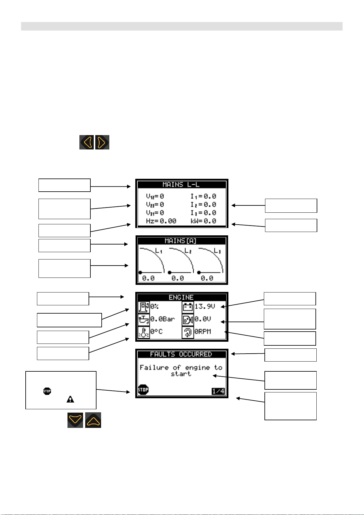
DISPLAY
The instruments displayed on the control unit are divided into groups. The groups are:
Mains
Generator
Engine instruments
CAN Bus instruments (if CAN Bus connection is enabled)
Counters
Maintenance (if maintenance hours have been set)
Rental (if rental hours have been set)
Fuel top-up management (if function is enabled)
Anomalies
Clock
Information about the control unit.
The two arrows are used to scroll through the instrument groups on the display or to select the sub-
menus under the settings.
The following are a few examples of instrument display menus.
The two arrows are used to move within the instrument groups or to scroll through the choices in the
settings menus.
Menu name
Line-to-line
voltages
Frequency
meter
Currents
Active power
Menu name
Fuel level
Temperature
Tachometer
Battery voltage
Pressure
D+ voltage
(input 66)
Icon identifying if
anomaly causes a
stop or does not
cause a stop .
Menu name
Anomaly
occurred
Menu name
Phase currents
Number of
active
anomalies

________________________________________________________________________________________________________
ELCOS –Parma –Italy –CAM-335 Valid for firmware revision 1.14 and above Page 5 of 20
To display instruments individually, simply touch the display on the relevant instrument. For example:
touching the D+ icon with your finger opens the menu that
displays the individual instrument.
To move inside the groups of instruments, you can either touch the arrows or the display. Each press of the button
displays the next instrument in the group.
For example:
and doing so will allow you
to browse through all the instruments.
________________________________________________________________________________________________________
ELCOS –Parma –Italy –CAM-335 Valid for firmware revision 1.14 and above Page 6 of 20
OPERATION
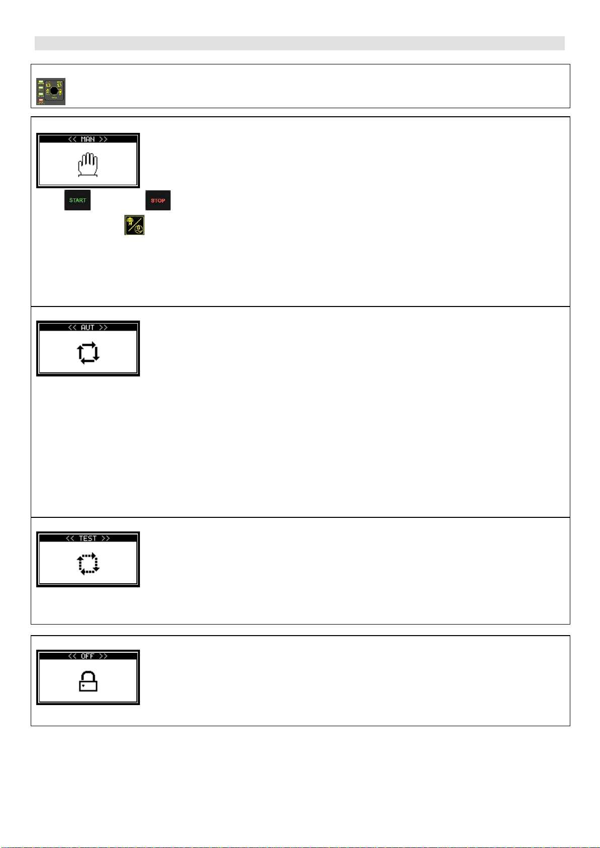
FUNCTION SELECTION
The function selected using the key is indicated by its light which goes on.
MANUAL
Image displayed when switched to manual.
Press to start and to stop (a quick press is sufficient).
Pressing the button switches the load from the mains to the generator and vice versa.
In manual mode, the generator protection function can be programmed in two ways:
Display the fault recorded and stop the engine (this is the default setting).
Only display the fault recorded, without stopping the engine. Generator overspeed and emergency anomalies
are programmed to shut down the engine; they cannot be programmed without engine shutdown.
AUTOMATIC
Image displayed when switched to automatic.
When a mains anomaly occurs —detected by the internal voltage relay inside the control unit or when the
external call delay has elapsed —the control unit commands the mains contactor to open and the genset to start.
With the engine running and with correct generator voltage and frequency, once the G.S. VOLTAGE PRESENT
DELAY has elapsed, the generator contactor is closed. When operating, the genset is protected from any anomalies.
When the mains voltage is restored and the MAINS VOLTAGE PRESENT DELAY has elapsed, the control unit
commands the generator contactor to open and after the GENERATOR MAINS INTERLOCK time has elapsed, the
mains contactor closes.
The COOLING TIME enables and facilitates subsequent engine cooling before it shuts down.
To facilitate start-up, a special circuit determines a series of start-up attempts, the number, pause duration and start-
up duration of which can be programmed. If running of the entire series of start-up attempts is unable to start the
engine, when the cycle is completed, STARTING FAILURE is displayed and the stop cycle starts.
TEST
Image displayed when switched to test.
In testing, the engine start-up cycle is obtained as in automatic mode, with the exception that the user remains
powered from the mains. If, during the test, a mains anomaly occurs, the control unit remains in test mode but
commands the generator contactor to close.
OFF
Image displayed when switched to off. When set to OFF, the engine cannot be started in any
way and, if it is running, it stops without the engine cooling step.

________________________________________________________________________________________________________
ELCOS –Parma –Italy –CAM-335 Valid for firmware revision 1.14 and above Page 7 of 20
PROGRAMMABLE OUTPUTS
WARNING!
Outputs 6, 19 and 70 can be associated to many functions (see programming manual under the section
“PROGRAMMABLE OUTPUTS”). It is NOT possible to simultaneously associate more than one function to an
output. For example, if fuel filling is associated to output 70, it is not possible to manage the general alarm from this
terminal and vice-versa. By default, management of glow plugs is associated to output 6, the signal that simulates the
15/54 to output 19, and the general alarm to output 70.
GLOW PLUG PREHEATING
Activation of the glow plug output is adjustable —from a minimum of 0 seconds (command off) to a maximum of
60 seconds —for both automatic and manual mode. Once activation has been completed, the engine start-up
procedure begins. Glow plug post-heating can also be managed, i.e. maintaining output live for a set amount of time,
even after the engine has been started (see programming manual).
ENGINE TYPES
The control unit can manage start-up of both diesel and petrol engines. Diesel engines allow for the connection of
the CAN bus line to the control units with electronic injection. For choice of engines, see the programming manual.
AUTOMATIC TEST
The automatic test is enabled only with the control unit on automatic. During the test, the generator set starts up
and stays running for the AUTOMATIC TEST DURATION time (programmed at 3 minutes). If a mains anomaly
occurs, the generator contactor closes. The display shows AUTOMATIC TEST during the test cycle. You can also
choose whether to run a commutation or not during the test (default setting: no commutation). Press STOP to stop the
engine during the test. The test will not be run if there is an anomaly. The automatic test can be performed in two
ways:
WEEKLY: the test will be run weekly at the time and on the day set.
MEASURED: the test can be programmed to run at cycles ranging from 1 to 30 days. The default setting is 7 days.
To enable the test, just enter User Programming and include the function. Once any one of the test parameters has
been set, it starts for the first time when one minute after quitting the setting mode has elapsed. If at that time the
conditions for starting the test are not present (e.g. because the control unit is not on automatic), the test will be run
at the next deadline. The time count starts all over again when the control unit is reset.
ENGINE RUNNING DETECTION
Engine running is detected by revealing the residual generator frequency and voltage and by detecting the
voltage and frequency of the battery charger alternator (permanent or pre-excitation magnets). When an engine with
electronic management is connected to the control unit, detection of the running engine occurs when the RPM read by
the CAN Bus line exceed the RUNNING ENGINE THRESHOLD RPM. Once detected, the starter motor switches off
and the green LED lights up
STOPPING SYSTEMS
Stopping can be achieved in two ways:
With the electromagnet or solenoid valve energized when the engine is running and de-energized when the
engine is stopped (default setting).
With the electromagnet de-energized when engine is running and energized when it is stopped, remaining in
this condition for the entire STOPPING TIME after engine not running has been detected.
If, after 120 seconds from receipt of the stop command, the control still detects the engine running signal, the
STOPPING FAILURE trips.
EMERGENCY STOP
This is available in all operating modes. It is possible to install (hook mount) one or more buttons. Stopping is
immediate, without engine cooling; it activates the general alarm and EMERGENCY STOP is displayed.
Do not use the emergency button in combination with a stopping system that is not energized while
running.
________________________________________________________________________________________________________
ELCOS –Parma –Italy –CAM-335 Valid for firmware revision 1.14 and above Page 8 of 20
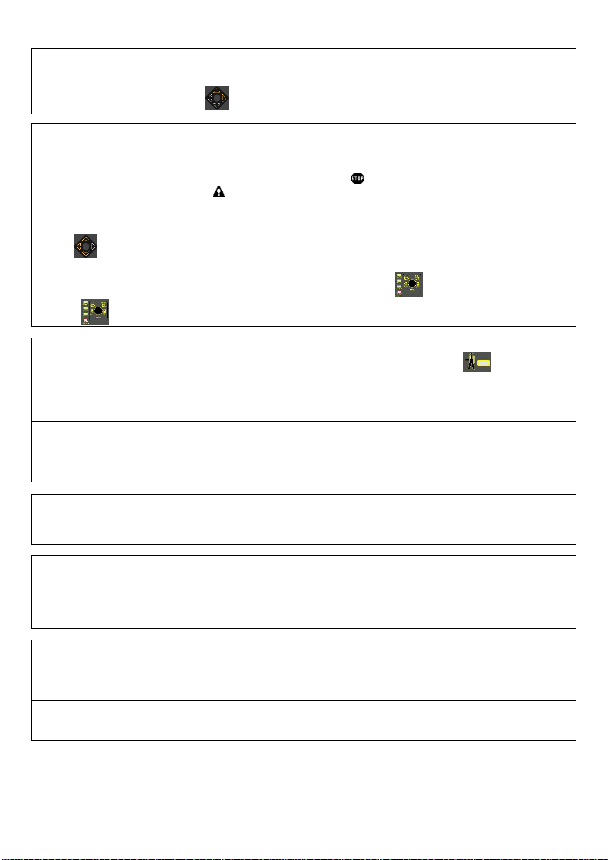
GENERAL ALARM
The general alarm can be obtained by installing a signal at the appropriate alarm terminal. It can be programmed
so that it is always on or remains on for a specific amount of time. It trips whenever the control unit detects an
anomaly. Pressing one of the arrows silences the alarm.
GENSET AND USER PROTECTIONS
Tripping of an anomaly is shown on the display and can cause the engine to cut out and activates the general
alarm. See the FAULT LIST table on page 17.
Normally the display shows the genset instruments; in the event of an anomaly, it displays the anomaly message
triggered. If the anomaly causes a stop, the red LED flashes and the icon lights up; if the anomaly does not cause
a stop, the yellow LED flashes and the icon lights up
If the anomalies are detected by the CAN Bus line connected to the engine’s electronic injection control unit, the
yellow and red LEDs light up and remain steady on.
Press the ARROW to review the instruments on the display and, at the same time, silence the general alarm, use one
of the 4 navigational arrows. After 20 seconds have elapsed since the last time the key was pressed, the display
reverts back to displaying the anomaly/anomalies that have occurred.
When OFF RESET lights up, the anomalies can be reset by pressing the key . If the OFF function is disabled,
press the key to reset the anomalies.
PREVENTIVE MAINTENANCE
When preventive maintenance operations are to be carried out, the flashing alarm light goes on and the
maintenance number that intervened is displayed along with the description set beforehand. If programmed, stopping
is also achieved with PROTECTION IN MANUAL bypassed and with the PROTECTION INHIBITION input active. The
procedure for resetting expired maintenance is to be performed only by genset manufacturer.
RENTAL FUNCTION
It is possible to programme the number of genset rental hours; after this time has elapsed, the control unit can
immediately block genset operation or can block it at the next start-up. If programmed, stopping is also achieved with
PROTECTION IN MANUAL bypassed and with the PROTECTION INHIBITION input active. Rental hours are counted
down when the engine is running.
STARTING GENSET WITH LOW BATTERY
When the battery is low, the genset can only be started up in automatic mode. When the voltage measured at the
battery terminals is below the minimum threshold, the engine will start and remain running until the maximum
threshold has been exceeded and the programmable delay time has elapsed.
START ON POWER REQUEST
The genset can only be started up on power request function when in automatic mode. When the power
absorbed by the power user is higher than the set threshold for the whole duration of the cut-in delay, the control unit
starts the generator set and switches the user to the generator. When the power absorbed by the power user is lower
than the set threshold for the whole duration of the cut-in delay, the control unit stops the generator set and switches
the user to the generator.
DAILY STARTING-STOPPING
The functions managed by the control unit’s internal clock are only active in automatic mode. Up to 10 genset
starts can be programmed, with relative switching of the power user to the generator at certain daily time slots.
It is also possible to program a genset lockout at a certain daily time slot.
CALL INPUT (TERMINAL 30)
Call input is active with control unit in automatic and test modes. When the contact closes to ground, operation is
the same as that of a mains failure.

________________________________________________________________________________________________________
ELCOS –Parma –Italy –CAM-335 Valid for firmware revision 1.14 and above Page 9 of 20
START INPUT (terminal 32)
The start input is active with control unit in automatic mode. When the contact closes to ground, REMOTE
START is shown on the display. When the REMOTE START DELAY time elapses, operation is the same as that of a
mains failure. When the start contact opens, operation is the same as when the mains power is restored. Other
functions can be associated to this input; see the programming manual.
STOP INPUT (TERMINAL 33)
The stop input is active with control unit in automatic mode. When the contact closes to ground, REMOTE STOP
is shown on the display. The control unit does not permit any start-up and, if the genset is running, it stops. Other
functions can be associated to this input; see the programming manual.
PROGRAMMABLE INPUTS (TERMINALS 41 and 42)
Inputs 41 and 42 are completely programmable (see the programming manual). The following settings are
possible:
Function, Text, Intervention delay, Stop, Cooling, Storage, Polarity, Activation.
MESSAGES AND CAN BUS INSTRUMENTS
Every message or instrument appearing on the display having to do with the injection control unit and read by the
CAN Bus line can be identified by the characters [ECU] shown in the lower right corner.
Anomaly messages are shown on the display as SPN, FMI and OC: SPN is a number identifying a particular
component of the diesel engine; FMI is a number identifying the failure or malfunction of the SPN component; OC
identifies the number of times this particular problem occurred in the engine.
If CAN Bus line connection between the two control units is interrupted, the message CAN Bus ANOMALY will
appear.
The instruments managed and displayed by the CAM-335 control unit are:
Instrument
Description
U.M.
Tachometer
Engine revolutions.
RPM
Oil pressure
Engine oil pressure.
BAR
kPa
Engine temperature
Engine water or oil temperature.
°C
°F
Fuel consumption
Amount of fuel consumed by the engine per unit of time.
l/h
Fuel temperature
Fuel temperature at injector inlet.
°C
°F
Turbo temperature
Temperature of turbo compressor oil.
°C
°F
Oil temperature
Temperature of engine oil.
°C
°F
Intercooler temperature
Temperature of fluid in the intercooler downstream the turbo
compressor.
°C
°F
Intake temperature
Temperature of pre-combustion air.
°C
°F
Coolant level
Coolant level.
%
Fuel pressure
Pressure of the fuel between the fuel pump and the injection
pump.
BAR
kPa
Coolant pressure
Pressure of coolant in the cooling system.
BAR
kPa
Engine torque
Engine output torque percentage.
Nm
Engine power
Power developed by the engine.
kW
Fuel level
Indicates fuel level
%
Oil level
Level of oil in the engine.
%
Electronic engines currently managed are: John Deere, Perkins, Scania, Volvo, Deutz, FPT, VM, Cummins and MTU.
ENGINE HEATING
Function can be activated in SCANIA engines with CAN Bus connection. It warms up the engine at idling speed
after it starts. The function takes both engine temperature and set time into account. When the engine reaches the set
temperature or set time, the control unit speeds up the engine to rated speed. This default function is disabled. See
the programming manual for instructions on how to set the temperature threshold and time. Heating can also be
managed for mechanical engines by activating the function in a programmable output and connecting an
electromagnet to the engine.

________________________________________________________________________________________________________
ELCOS –Parma –Italy –CAM-335 Valid for firmware revision 1.14 and above Page 10 of 20
EJP FUNCTION
To activate the EJP function, see the programming manual. It is only active in automatic mode. When the contact
connected to terminal 32 closes to ground, EJP STARTUP is shown on the display. After the EJP STARTING DELAY
has elapsed (set to 25 minutes), the start-up cycle begins. When the contact connected to terminal 33 closes to
ground, EJP SWITCHING CONSENT is shown on the display and operation is the same as that of a mains failure.
When the two contacts open, operation is the same as when mains power is restored.
VOLTMETRIC CONNECTIONS
The control unit can be configured to manage THREE-PHASE, TWO-PHASE and SINGLE-PHASE voltages. This
selection is valid both for the mains and for the generator; therefore, it is possible to manage, for example, three-
phase voltage from the mains and two-phase from the generator. When the mains power is three-phase, the phases
must be connected to terminals 91, 92 and 93 and the neutral to terminal 90. With two-phase connection, terminals
91 and 92 must be connected and the neutral must not be connected. Instead, with the single-phase connection, the
phase must be connected to terminal 92 and the neutral to terminal 90. Likewise, when the generator power is three-
phase, the phases must be connected to terminals 96, 97 and 98 and the neutral to terminal 95. With two-phase
connection, terminals 96 and 97 must be connected and the neutral must not be connected. Instead, with the single-
phase connection, the phase must be connected to terminal 97 and the neutral to terminal 95.
MAINS/GENERATOR VOLTMETRIC RELAYS
The voltmetric relays are located inside the control unit and serve to control the mains and genset voltages and
frequencies. The parameters considered are: power failure, undervoltage, overvoltage, asymmetrical voltages,
incorrect phase sequence, under-frequency and overfrequency.
Mains voltmetric relay: when each parameter has been accepted individually, after the mains voltage present
delay has elapsed (programmed to 100 seconds), if the genset is running, it stops and the mains contactor is
energized.
Generator voltmetric relay: when each parameter has been accepted individually, after the generator voltage
present delay has elapsed (programmed to 7 seconds), the generator contactor closes. It takes just one
parameter outside the normal range to de-energize the generator contactor.
FUEL FILLING MANAGEMENT
When the automatic fuel filling function is enabled, a dedicated menu is displayed. With filling, the fuel is
transferred from a storage tank to the genset tank. Either automatic mode, manual mode or filling lockout can be
selected using the display touch screen. The filling function is managed independently, meaning it does not depend
on the control unit’s operation mode. It is possible to enable filling either when the genset is powered or when the
user is powered. A contact float controls the maximum safety level. Another float with variable resistance (terminal
37) manages activation and deactivation of the output for pump and/or solenoid valve piloting. If the function is
enabled by default, the pump relay piloting output is associated to terminal 70, while the maximum level float input is
associated to terminal 41.
To change the filling management operation mode, simply press “AUT”, “MAN” or “OFF” on the display. The mode is
saved in the control unit even if the battery gets disconnected.
Automatic filling: when the level of fuel drops below the “minimum level”, the output is
enabled and MINIMUM FUEL LEVEL appears on the display. When the “maximum level” is
exceeded, the output is disabled and MAXIMUM FUEL LEVEL appears on the display.
Manual filling: pressing the START button on the display enables the filling output; taking the
finger off the button disables the output.
Filling OFF: turns filling off; the output, if enabled, is disabled.
Request the connection diagram, which can also be downloaded from the website www.elcos.it.

________________________________________________________________________________________________________
ELCOS –Parma –Italy –CAM-335 Valid for firmware revision 1.14 and above Page 11 of 20
FICTITIOUS LOAD MANAGEMENT
This allows inserting a minimum load when the power absorbed by the power user does not exceed the
threshold. When the function is enabled and with the engine running and normal electrical parameters, the “fictitious
load” output and, where required by the mode, the genset’s contactor, are activated simultaneously. Fictitious load
remains on as long as the power absorbed by the power user does not exceed the off threshold. When the power
exceeds the threshold, fictitious load is disabled. It will be enabled once again when the user power drops below the
activation threshold. Request the connection diagram, which can also be downloaded from the website www.elcos.it
IMMINENT START WARNING
With the exception of start-ups due to power failure or closing of a call contact, every automatic start-up is
preceded by the intermittent activation of the general alarm output for 8 seconds; then, 3 seconds later, the start-up
cycle begins. If a buzzer is connected to this output, the operator is notified that start-up is imminent. This function
can be bypassed. Warning: the output can be associated to other functions; see the programming manual.
PASSWORD
Access to technical settings is password activated. There are 7 password levels, each level gives access to
different settings. The default password settings are all “0000” and it is possible to enter the settings without entering
any other codes, except for level 7. To change the codes and activate the passwords, see the programming manual.
The list of the 7 levels is given below:
1. The operator can read all the settings but cannot edit them.
2. Access in editing mode to rental hours and history log from maintenance hours.
3. Access only for resetting expired maintenance.
4. Access only for resetting expired rental blocks and for GSM block.
5. The operator can read and edit all settings.
6. Access in editing mode to total operating hours.
7. Access to the device menu.
For example: if we wish to prevent the operator from modifying the total operating hours, we must set a different
password to “0000” in level 6, for example “1234”. Doing this, we can enter the technical settings using the default
password (“0000”), but will not have access to the operating hours. To access the operating hours menu we must
enter the password “1234”.
SERIAL NUMBER (ID)
It is possible to programme an alphanumeric serial code in the control unit. This number is displayed every time
the control unit is switched on; it can be read in the INFORMATION menu or by pressing the left arrow for 4 seconds.
Refer to the programming manual.
SERIAL PORTS
The control unit has 4 serial ports: RS232, RS485, USB 2.0 and CAN Bus.
RS232: used to connect the control unit:
oto a personal computer, for setting parameters with the ZW-100-PR software
oto a personal computer for the ZW-100 remote operation software
oto Ethernet interface with the ZW-100 remote operation software
oto GSM modem for text message management.
RS485: used to communicate with:
oinput/output expansion modules
othe remote panel
othis port can be used in slave mode so that an external device can poll the control unit using the MOD
Bus RTU protocol.
USB 2.0: used to connect the control unit:
oto a personal computer, for setting parameters with the ZW-100-PR software
oto a personal computer for the ZW-100 remote operation software.
CAN Bus: used to connect the control unit to the CAN Bus line of electronic engines with SAE J1939 protocol.
________________________________________________________________________________________________________
ELCOS –Parma –Italy –CAM-335 Valid for firmware revision 1.14 and above Page 12 of 20
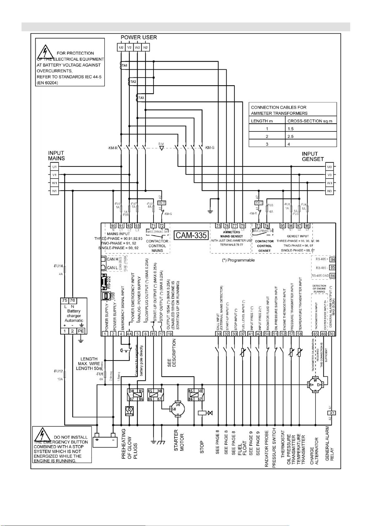
CONNECTION DIAGRAM
Basic diagram for illustration purposes, subject to change without notice.
________________________________________________________________________________________________________
ELCOS –Parma –Italy –CAM-335 Valid for firmware revision 1.14 and above Page 13 of 20
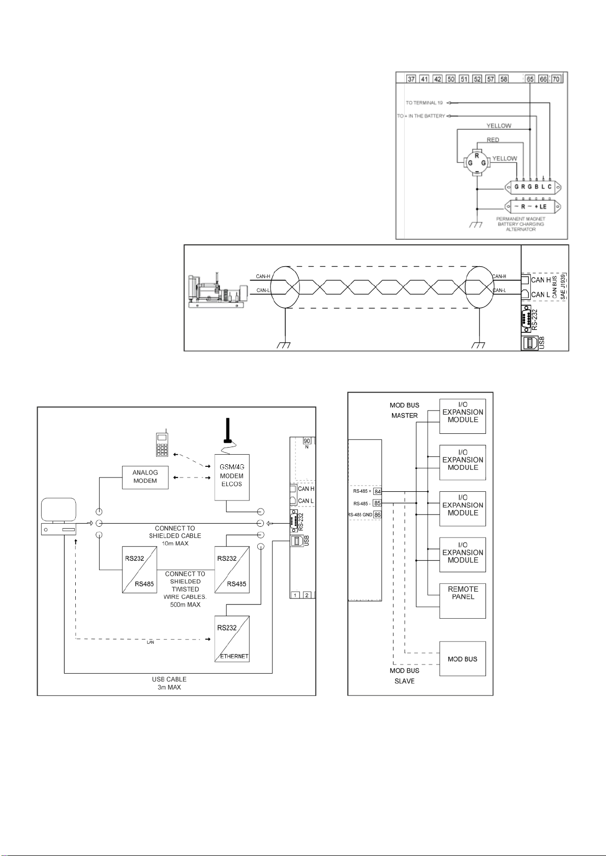
Detail of connection of the control unit to a permanent magnet battery charger alternator. For different controllers,
request diagram.
Detail of connection of the
control unit to an electronic
engine via CAN Bus. Use an
insulated twisted-wire cable
not longer than 40 metres. For
additional details, request the
diagrams for the specific
engines.
In the manual for the control unit (ECU/ECM), read if inserting the 120ohm 1/4W termination resistor, engine side,
between the CAN-H and CAN-L wires is required.
Once the connections have been made and powered, the control unit is set to OFF. See programming to
change this status.
The above diagram indicates the different
types of connections for the RS232 port.
The RS485 serial port can act as a master
to manage expansions and / or time
synchronization of other control units,
horaire, as a slave to be polled by external
devices.
________________________________________________________________________________________________________
ELCOS –Parma –Italy –CAM-335 Valid for firmware revision 1.14 and above Page 14 of 20
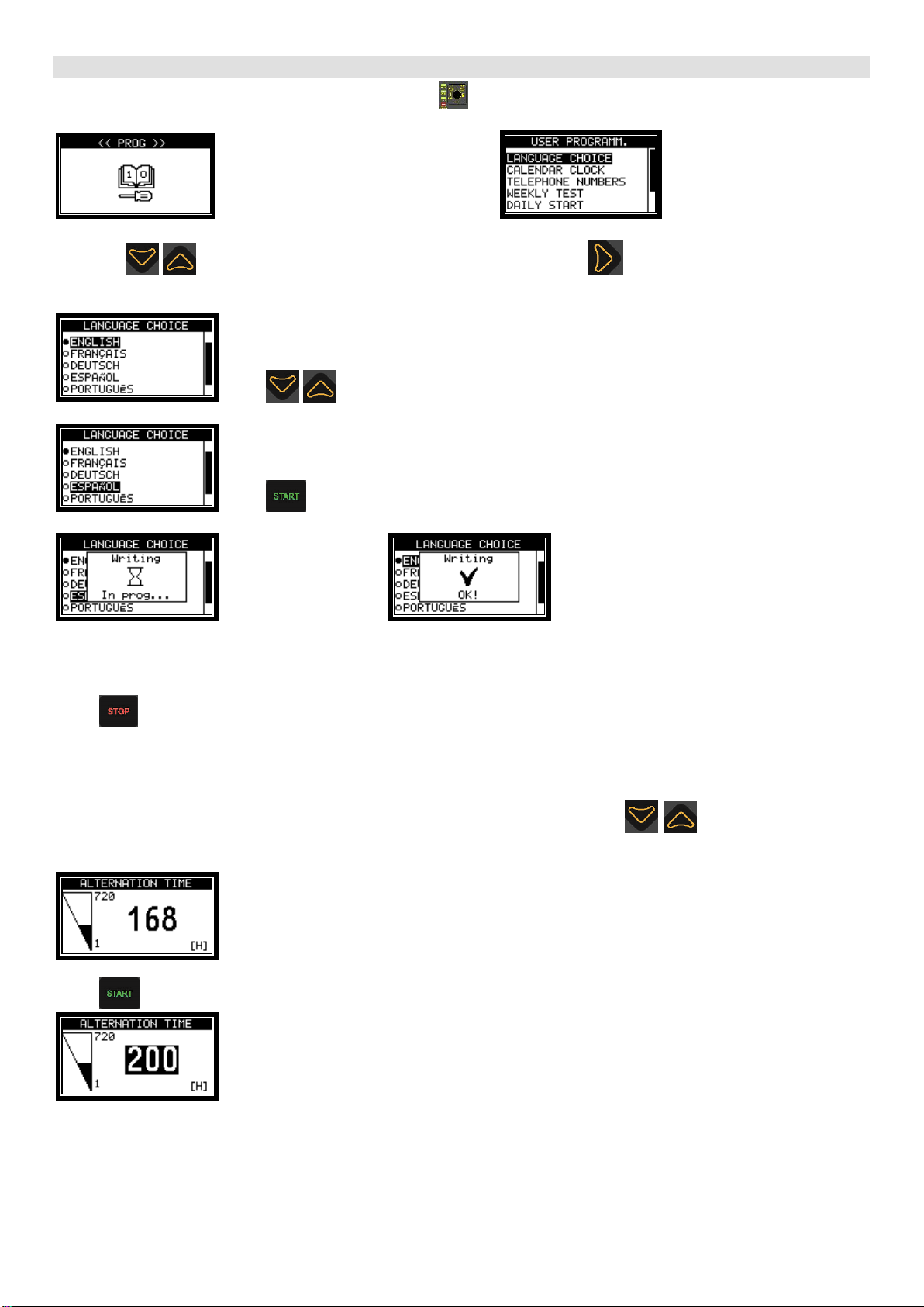
USER PROGRAMMING
To access user programming, press the FUNCTION key and keep it pressed until “PROG” appears on the
display.
Release the button. After a few seconds appears
Press the arrows to scroll through the programming menus. Press to enter the desired sub-menu. For
example:
Press to scroll through the programming items. For example:
Press to confirm the selection. The following appears:
Wait for a few seconds:
The chosen parameter is now programmed in the control unit. The settings are stored in a non-volatile memory, and
are therefore maintained even if the power is switched off. The value can be modified at any time by repeating the
procedure as described above.
Press to return to the previous menu and then proceed to program the other parameters.
Programming a numerical parameter.
When programming a numerical parameter, such as a threshold or a time, press to increase or decrease
the parameter.
Press to confirm the value. When the number is saved in the control unit, it changes colour.
________________________________________________________________________________________________________
ELCOS –Parma –Italy –CAM-335 Valid for firmware revision 1.14 and above Page 15 of 20
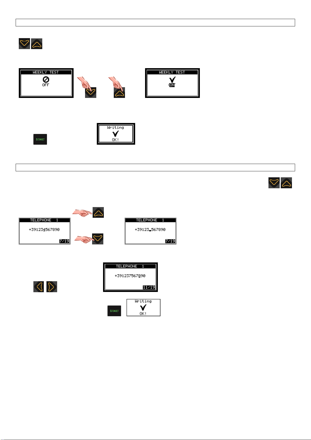
Enabling/disabling a parameter.
When programming a binary parameter (enabled/disabled), for example, enabling the weekly automatic test, press
to enable or disable the parameter. For example:
or
Press to confirm the value.
Programming a number.
When programming a numerical code such as, for example, telephone numbers for the GSM modem, press
to edit the number indicated by the cursor. For example:
Press to move the cursor
Confirm the programming by pressing .

________________________________________________________________________________________________________
ELCOS –Parma –Italy –CAM-335 Valid for firmware revision 1.14 and above Page 16 of 20
User-programmable parameters are:
Parameter
Range
Default setting
Notes
LANGUAGE CHOICE
ITALIAN
ITALIAN
A CUSTOM language
cannot be selected unless
the messages have been
programmed with the
software
ZW-100-PR.
ENGLISH
FRENCH
GERMAN
SPANISH
PORTUGUESE
CUSTOM
CLOCK/CALENDAR
Standard
Calendar clock adjustment.
TELEPHONE NUMBERS
TELEPHONE 1
16 digits
Empty
Telephone numbers to
which text messages will be
sent with the GSM modem.
TELEPHONE 2
16 digits
Empty
TELEPHONE 3
16 digits
Empty
WEEKLY TEST
OFF
OFF
ENGAGED
DAILY START
START 1
00:00 ÷ 23:59
--:-- ÷ --:--
With --:-- ÷ --:-- starting is
off.
START 2
00:00 ÷ 23:59
--:-- ÷ --:--
START 3
00:00 ÷ 23:59
--:-- ÷ --:--
START 4
00:00 ÷ 23:59
--:-- ÷ --:--
START 5
00:00 ÷ 23:59
--:-- ÷ --:--
START 6
00:00 ÷ 23:59
--:-- ÷ --:--
START 7
00:00 ÷ 23:59
--:-- ÷ --:--
START 8
00:00 ÷ 23:59
--:-- ÷ --:--
START 9
00:00 ÷ 23:59
--:-- ÷ --:--
START 10
00:00 ÷ 23:59
--:-- ÷ --:--
DAILY STOP
00:00 ÷ 23:59
--:-- ÷ --:--
With --:-- ÷ --:-- stopping is
off.

________________________________________________________________________________________________________
ELCOS –Parma –Italy –CAM-335 Valid for firmware revision 1.14 and above Page 17 of 20
FAULT LIST
The complete list of anomalies managed by the control unit is given below.
Fault
code
Description
Occurs when:
111
MAINTENANCE 1
Maintenance 1 expired.
112
MAINTENANCE 2
Maintenance 2 expired.
113
MAINTENANCE 3
Maintenance 3 expired.
114
PROGRAMMED MAINTENANCE
Programmed maintenance expired.
115
RENTAL HOURS
The rental hours have expired.
120
BATTERY UNDERVOLTAGE
The battery voltage is lower than the set threshold.
121
BATTERY OVERVOLTAGE
The battery voltage is higher than the set threshold.
122
ENGINE LOW TEMPERATURE
The engine has not reached the set temperature.
123
OVERTEMPERATURE PRE-ALARM
The engine has exceeded the overtemperature pre-alarm threshold.
124
PRE-ALARM
The engine has exceeded the overtemperature threshold read by the
transmitter.
125
THERMOSTAT OVERTEMPERATURE
The engine thermostat has cut in.
126
MAXIMUM FUEL LEVEL
The maximum top-up level contact float has cut in.
129
FUEL RESERVE
The fuel level is lower than the reserve threshold.
130
NO FUEL
The fuel level is lower than the set threshold.
131
LOW OIL PRESSURE PRE-ALARM
The engine oil pressure does not exceed the set threshold.
132
LOW OIL PRESSURE
The engine oil pressure switch has cut in.
133
STOPPING FAILURE
Detects that engine is running even if the stopping system has been
activated.
135
LOW RADIATOR LEVEL
Insufficient radiator coolant.
136
CHARGING ALTERNATOR
The output “D+” or “W” on the charging alternator does not work.
137
STARTING FAILURE
The control unit has attempted to start the generator, but the engine is not
running.
139
OVERSPEED
The RPMs detected by the control unit have exceeded the set threshold.
140
FUEL FLOAT INTERRUPTED
The electrical circuit for the fuel float is interrupted.
141
OIL PRESSURE SWITCH ANOMALY
The oil pressure switch contact is open with the engine switched off.
220
GENERATOR UNDERVOLTAGE
The genset voltage is lower than the set threshold.
221
GENERATOR OVERPOWER
The power absorbed by the generator has exceeded the alarm threshold.
222
GENERATOR OVERVOLTAGE
The genset voltage is higher than the set threshold.
223
GENERATOR UNDERFREQUENCY
The genset Hz value is lower than the set threshold.
224
GENERATOR OVERFREQUENCY
The genset Hz value is higher than the set threshold.
225
GENERATOR OVERLOAD PRE-ALARM
The current absorbed by the genset has exceeded the pre-alarm
threshold.
226
GENERATOR OVERLOAD
The current absorbed by the genset has exceeded the alarm threshold.
227
GENERATOR NOT DELIVERING
Although running, the genset does not deliver voltage.
228
GENERATOR CONTACTOR FAULT
The generator contactor does not open or close.
230
GENERATOR PHASE SEQUENCE
The sequence of the three genset phases is not correct.
231
GENERATOR ASYMMETRY
The voltages between the three genset phases are not similar.
322
MAINS CONTACTOR FAULT
The mains contactor does not open or close.
323
MAINS PHASE SEQUENCE
The sequence of the three mains phases is not correct.
325
MAINS OVERLOAD
The current absorbed by the mains has exceeded the alarm threshold.
419
EMERGENCY STOP
The emergency button has been pressed.
421
AVAILABLE ANOMALY 41
The anomaly associated with programmable input 41 has occurred.
422
AVAILABLE ANOMALY 42
The anomaly associated with programmable input 42 has occurred.
426
AVAILABLE ANOMALY 32
The anomaly associated with programmable input 32 has occurred.
427
AVAILABLE ANOMALY 33
The anomaly associated with programmable input 33 has occurred.
430
CAN BUS
The control unit does not receive data from the CAN Bus line.
431
ENGINE CONTROL UNIT
Engine fault detected by the electronic control unit (ECU).
443
FUEL FLOAT TABLE ERROR
The float table has been programmed with errors.
446
OIL PRESSURE TRANSMITTER TABLE ERROR
The oil pressure transmitter table has been programmed with errors.
447
TEMPERATURE TRANSMITTER TABLE ERROR
The temperature transmitter table has been programmed with errors.
449
KEYBOARD ERROR
The control unit turns on with at least one button pressed.
500
NO GSM MODEM
The GSM modem does not communicate with the control unit.
501
SIM NOT INSTALLED
There is no SIM card installed in the GSM modem.
502
SIM BLOCKED
The PIN code of the SIM Card installed in the modem is active.
503
GSM CODE ERROR
The GSM modem has detected a coded error.
504
GENERIC GSM ERROR
The GSM modem has detected a non-coded error.
505
NO REMOTE PANEL COMMUNICATION
The remote panel does not respond to the control unit data request.
506
I/O EXP. 1 FAULT
The input/output expansion module does not respond to the data request.
507
I/O EXP. 2 FAULT
The input/output expansion module does not respond to the data request.
508
I/O EXP. 3 FAULT
The input/output expansion module does not respond to the data request.
509
I/O EXP. 4 FAULT
The input/output expansion module does not respond to the data request.
510
RTCK SYBCHR.1 FAILED
RTCK synchronization of control unit 1 failed.
511
RTCK SYBCHR.2 FAILED
RTCK synchronization of control unit 2 failed.
512
RTCK SYBCHR.3 FAILED
RTCK synchronization of control unit 3 failed.
513
RTCK SYBCHR.4 FAILED
RTCK synchronization of control unit 4 failed.
556
BLOCK VIA GSM
The control unit is blocked by a text message command.
-
MDE-088 [01 –32]
The error associated to I/O module programmable input has occurred.
-
EEPROM ERROR
Failed access to the static memory.
________________________________________________________________________________________________________
ELCOS –Parma –Italy –CAM-335 Valid for firmware revision 1.14 and above Page 18 of 20
TECHNICAL SPECIFICATIONS
Power supply
Suitable for batteries
12Vdc
24Vdc
Operating range
8 ÷ 48Vdc
Absorption with engine not running
130mA to 12Vdc
90mA to 24Vdc
Voltage dip on battery power supply
From 10Vdc to 0Vdc for 250ms
Digital inputs
Type of input
Negative
Maximum current supplied
0.30mA
Voltage threshold for low signal
≤ 0.2Vdc
Voltage threshold for high signal
≥ 2Vdc
Terminal input 65
AC voltage
5.5 ÷ 65Vac
Measurement range
50 - 1500Hz
Mains and generator voltmetric inputs
Dielectric strength voltage between battery voltage circuits and
mains/generator voltage circuits
3750Vac 50Hz 1sec
Rated insulation voltage
Mains voltage terminal
600Vac
Genset voltage terminal
600Vac
Battery voltage terminal
48Vac
Insulation class
1
Measurement range
80 ÷ 570Vac (three-phase)
45 ÷ 340Vac (single-phase)
Accuracy
±1%
Frequency meter
Measurement range
45 - 85Hz
Accuracy
±0.1Hz
Amperometric inputs
Measurement range
20mA ÷ 6Aac
Amperometric transformer ratio
/5
Maximum displayable current
4800Aac
Accuracy
±1%
Digital outputs
Type of output
Positive (battery voltage)
Maximum load
Terminal 6, 15, 19, 70.
0.25 A
Terminal 17
1.5 A
Contactors command outputs
Type of output
Dry contact
Maximum applicable voltage
275Vac
Maximum load
3 A
Displayed powers (kW, kVAR, kVA, kWh)
Accuracy
±2%
Engine instruments
Oil pressure
0 ÷ 360Ohm
0.0 ÷ 9.0BAR
0 ÷ 900kPa
Temperature
0 ÷ 3000Ohm
0 ÷ 140°C
0 ÷ 284°F
Fuel level
0 ÷ 360Ohm
0 ÷ 100%
Accuracy (pressure gauge, thermometer, fuel level)
±2%
Lines of communication
RS232 (No optoisolator)
Baud-rate
1200 ÷ 115200 bps
Parity
None/even
RS485 (No optoisolator)
Baud-rate
1200 ÷ 115200 bps
Parity
None/even
USB 2.0 (Micro USB-B)
Interface
Not isolated. Maximum cable length 3 m.
CAN Bus (No optoisolator)
Baud-rate
250kbps
Protocol
SAE J1939
Environmental conditions
Operating temperature
-20 ÷ 60°C
Storage temperature
-20 ÷ 60°C
Relative humidity
≤ 80%
Vibration resistance
1g on the 3 axes (CEI EN 60068-2-6)
Impact resistance
15 on the 3 axes (CEI EN 60068-2-27)
Protection class
Back
IP 20
Front
IP 64
Container
Weight
480g
Dimensions (LxHxW)
157x109x74mm
Perforations
137x88 mm
________________________________________________________________________________________________________
ELCOS –Parma –Italy –CAM-335 Valid for firmware revision 1.14 and above Page 19 of 20
WARNING
Performs only genset control and command functions. It controls the mains and generator contactors for user power supply. It is
designed solely to be built into an electrical panel and connected to the other components (contactors, fuses, thermal magnetic
switches, etc.) the installer has arranged to complete the system.
Attention: Parts powered with dangerous voltages
The control unit can only be accessed by specifically assigned, duly trained personnel. Maintenance
operations cannot be performed unless the system is disconnected from the mains and the battery. As an
additional protection measure, we recommend grounding the system phases.
Notwithstanding the above, only specifically assigned, duly trained personnel can perform the following
operations with the system powered:
-visual inspection of control unit connections and markings;
-taking voltage and/or current measurements;
-function programming.
These works must always be performed using equipment that ensures appropriate electrical protection.
Warning:
Compliance with the following recommendations is obligatory
- Always make connections following the wiring diagram shown on page 12-13.
- All works performed on the unit must be carried out with the engine off and with starter motor terminal 50 disconnected.
- Check the consumption of the connected devices is in line with the described technical specifications.
- The installation must always guarantee adequate dissipation of heat.
- Always install the device at a lower position than any other devices that produce or dissipate heat.
- Handle and connect without exposing the electronic circuit board to mechanical strain.
- Do not let cuttings of copper conductors or other metal residues drop onto the control unit.
- Never disconnect the battery terminals while the engine is running.
- Strictly avoid using a battery charger for emergency start-up; this could damage the control unit.
- To safeguard persons and equipment, always disconnect the electrical system terminals from the battery poles before
connecting an external battery charger.
THIS UNIT IS NOT SUITABLE FOR WORKING UNDER CONDITIONS WHERE:
- The room temperatures exceeds the limits specified in the technical data sheet.
- Abrupt shifts in temperature and air pressure produce exceptional condensation.
- There is high pollution caused by dust, fumes, vapour, salts and corrosive or radioactive particles.
- There is high radiation of heat due to direct sunlight, ovens or the like.
- You suspect the presence of mould or pests.
- There is a danger of fire or explosion.
- Strong shocks or vibrations can be transmitted to the control unit.
- The control unit is protected by barriers or casings with a protection rating below IP40.
ELECTROMAGNETIC COMPATIBILITY
This control unit works correctly only if it is installed in systems that comply with regulations governing CE marking; in fact,
it complies with the immunity requirements given in EN61326-1, but this does not rule out the possibility that
malfunctions could occur in extreme cases that may arise in particular situations.
The installer is responsible for checking that the level of perturbation does not exceed that specified in standards.
OPERATION AND MAINTENANCE
We recommend the following maintenance on a weekly basis:
-signal operation checks;
-battery status checks;
-conductor tightness and terminal status checks.
IN THE ABSENCE OF OUR WRITTEN DECLARATION ATTESTING TO THE CONTRARY, THIS UNIT IS NOT SUITABLE FOR USE AS A
CRITICAL COMPONENT IN EQUIPMENT OR SYSTEMS VITAL TO THE LIFE OF PEOPLE AND OTHER LIVING THINGS.
YOUR ELECTRICIAN MAY TELEPHONE OUR TECHNICAL SERVICE WITH ANY QUESTIONS REGARDING THIS CONTROL
UNIT

________________________________________________________________________________________________________
ELCOS –Parma –Italy –CAM-335 Valid for firmware revision 1.14 and above Page 20 of 20
INFORMATION FOR ORDERING
Type
Item Code
CAM-335
00242262
STANDARD ACCESSORIES
Type
Item Code
KIT MU CAM-335
40804479
ACCESSORIES AVAILABLE ON REQUEST
Type
Item Code
EXPANSION MODULE MDE-088
00242269
ETHERNET INTERFACE ZE-100
00070227
GSM MODEM AMD-RB900 PRO
00070218
Programming software ZW-SMART
00070212
DOCUMENTATION ON REQUEST
Downloadable from the website www.elcos.it/
Diagram
number
Petrol engine diagram
00000731
Automatic fuel filling diagram
00000732
Fictitious load diagram
00000733
Connection diagram with expansion modules
00000734
Connection diagram with voltage transformers
00000735
Connection diagram with contact float
00000736
List of MOD Bus CAM-335 addresses
Other manuals for CAM-335
1
Table of contents
Other ELCOS Control Unit manuals

ELCOS
ELCOS DCA-110 User manual

ELCOS
ELCOS CAM 684 User manual

ELCOS
ELCOS CAM-685 User manual

ELCOS
ELCOS DCA-120/10 Owner's manual

ELCOS
ELCOS CIM-137/4G Instruction Manual

ELCOS
ELCOS CEP-337 User manual

ELCOS
ELCOS CIM-130 Instruction Manual

ELCOS
ELCOS CIM-131 Instruction Manual

ELCOS
ELCOS CAM-432 Instruction Manual

ELCOS
ELCOS CEP-090 User manual


