ELCOS DCA-110 User manual

ELCOS- Parma- Italy - gb - DCA-110 1
Automatic faults surveillance with messages on the display
Texts in 6 languages: Italian, English, rench, German, Spanish and Portuguese
Remote control (start and stop)
Glow plugs preheating management or engine heating cooling
Clock for programming the starting or the stopping of the engine
Preventive maintenance warning
Programmable weekly selftest
Available fully programmable input for anomaly
CAN Bus SAE J1939
Possibility of starting the engine when the charge of the battery is low
Anomaly historical record (Including data from the last 100 occurred anomalies)
PARMA
ITALY
(PDLOLQIR#HOFRVLW+773ZZZHOFRVLW
)D[
7HO
CONTROL UNIT FOR AUTOMATIC DIESEL ENGINE
TYPE DCA-110
This carries out the control and command function of a diesel engine.
It is equipped with display
to show THE
INSTRUMENTS:
(simultaneous reading of 4)
- battery voltmeter
- total hour meter
- partial hour meter
- starting counter
- starting failures counter
- fuel level
indicator
- tachometer
OPERATING AND INSTRUCTION MANUAL
or pwater pump protection (Protection device used in irrigation systems)

ELCOS- Parma- Italy - gb - DCA-110
2
OFF
AUT
MAN
6723
%
PRESS BRIEFLY
TO SHOW THE
INSTRUMENTS,
HOLD DOWN
TO VERIFY
THE LED TEST.
GENERAL ALARM
SILENCING
THE OPERATION
MODE OF THE
CONTROL UNIT IS:
• MANUAL
• AUTOMATIC
• OFF
• USER
PROGRAMMING
BATTERY
VOLTMETER
PRESS TO
STOP THE
ENGINE
WHEN THE
CONTROL
UNIT IS IN
MANUAL
OPERATION
PRESS TO
START THE
ENGINE WHEN
THE CONTROL
UNIT IS IN
MANUAL
OPERATION
MODE
ENGINE IS
RUNNING
%5,(),16758&7,216
PRESS TO
RESET
THE
CONTROL
UNIT
PREVENTIVE
MAINTENANCE
AND CUMULATIVE
ALARM WITHOUT
STOPPING
PRESS TO
SELECT THE
OPERATION MODE:
• MANUAL
• AUTOMATIC
• OFF
• USER
PROGRAMMING
STARTING
COUNTER
STARTING
FAILURE
COUNTER
,167580(176
With the running
engine the gengine
instruments are
shown.
In the event of a fault,
instead of the
measurement, the
display shows the
message of the
occurred fault.
• BATTERY VOLTMETER For voltages ranging between 9 and 38 Volt.
• TOTAL HOUR-METER With five digits and a maximum reading of 59999 (hours
and minutes).
• PARTIAL HOUR-METER With four digits and a maximum reading of 9999 (hours
and minutes). (The hours indicated are zero-set the next time
the engine is started up.)
• STARTING COUNTER Displays the number of startings that have occurred up
to 9999.
• STARTING FAILURE Displays the number of failure startings that have occurred
COUNTER up to 65535.
• FUEL LEVEL Displays the percentage of fuel present in the tank
INDICATOR
• TACHOMETER 8500 rpm.Displays the number of engine revs up to
6,08/7$1(2865($',1*2)7+(,167580(176:,7+7+(5811,1*(1*,1(
INDICATOR, .FUEL LEVEL TACHOMETER, HOUR-METER
5(9,6,216+,6725<
Date
Level of the
REVISION
Description Page
CUMULATIVE
ALARM WITH
ENGINE STOP
THE CALL
IS CLOSED
TOTAL
HOUR METER
TACHOMETER
FUEL
LEVEL
INDICATOR

ELCOS- Parma- Italy - gb - DCA-110 3
The function selected
with the key is shown by
the associated warning light.
The control unit commands are enabled.
Starting with key stopping with key (it is obtained by pressing once the key).
0$18$/
23(5$7,21
)81&7,2166(/(&7,21
OFF
AUT
MAN
6723
67$57
$8720$7,&
On closing the call contact,
(if set) and
On the opening the call contact,
once the STARTUP DELAY AFTER CALL time (programmed to 1 sec.) has elapsed,
the control unit switches on the glow plugs then starts the engine.
and after the DELAY AFTER CALL OPENING time has elapsed, the engine stops.
:((./<6(/)7(67
ENABLED WITH POWER UNIT IN AUTOMATIC MODE (for programming see page 8 of the Technical Programming
Manual)
the engine starts and continues to run for the WEEKLY TEST TIME (programmed to 3 minutes). This test
will be repeated automatically every week on the exact day and at the hour to which it has been programmed.
During the automatic test cycle, WEEKLY TEST IN PROGRESS is shown on the display.
STOPPING OF ENGINE DURING THE TEST
Press key
If the engine remains stopped for a few days a week, we advise
extending the duration of the weekly test to charge the battery by
means of the battery charging alternator.
WEEKLY TEST STOP: the weekly test is stopped when an anomaly
is displayed on the display.
When key is pressed until Led comes on.
The engine cannot be started in any way and, if running, is stopped
2))
OFF
AUT
MAN
PROTECTIONS
The engine protection function in manual mode can be programmed in two ways:
· Display only of the fault that has intervened WITHOUT STOPPING the engine. The overspeed fault is programmed
with stopping of the engine. It cannot be programmed without stopping of the engine.
· Display of the fault that has intervened WITH ENGINE STOPPING. (The control unit is programmed in this way).
6723
67$57,1*
-
In on closing the call contact and after the STARTUP DELAY AFTER CALL time has elapsed.
To make starting easier, a special circuit establishes a series of programmable startups (programmed to 4
STARTUPS); the number of startups, the length of the pause time and the startup time can be programmed.
If the whole series of attempts is unable to start the engine, at the end of this cycle STARTING FAILURE
is shown on the display and the stop signal is activated.
DXWRPDWLF
STARTING FAILURE
'(7(&7,212)5811,1*(1*,1(
This is obtained by the detection of the battery charger alternator voltage (PERMANENT MAGNETS or PRE-
EXCITATION) or by the signal sent (CAN Bus) from the engine equipped with control unit for electronic control of
the injection system; in this case, the alternator only controls belt breakage and not engine running.
When detection has been made, this disconnects the starter motor and lights the LED .
- In with key .
PDQXDO
-
-
In with key (it is obtained by pressing once the key).
In it is activated automatically before starting.
The preheating action time can be adjusted, the preheating action stops before startup start.
The factory preheating command is inhibited as it has been programmed to zero seconds.
PDQXDO
DXWRPDWLF
*/2:3/8*635(+($7,1*
6723
- .
-
In mode using key (it is obtained by pressing once the key)
In mode on opening the call contact, or when the protection systems intervene.
Stopping can occur in two ways:
• With the solenoid deactivated while the engine is running and activated when stopped. This condition is maintained
during the STOPTIME (programmed to 20 seconds) after the engine stopped detection.
• With solenoid or electro-valve activated while the engine is running and deactivated when stopped.
This condition is maintained even when the engine is stationary.
PDQXDO
DXWRPDWLF
67$57
67$57
6723
The intervention of the fault is displayed; it can cause the engine to be stopped and activates the general alarm. See
TABLE at page 10 of the TECHNICAL PROGRAMMING manual.
When the engine is running the engine instruments are shown.
When there is a fault, instead of the reading, the display shows the intervened fault message, and the associated
LED flashes.
)$8/7',63/$<
)$8/75(6(7
It is possible to access the reading of the measurements by pressing key for 1 second.
The display will resume showing the previous fault 10 seconds after the last pressing of the key.
On pressing the key , the protection devices and all the locked functions are reactivated.
+2:726((7+(,167580(175($',1*6$*$,1
(1*,1(3527(&7,21'(9,&(6
Can be combined with the GLOW PLUG PREHEATING (factory programming) or functions (to
combine the function see page 5 of the technical programming manual).
HEATING: after starting the engine stays decelerated for a time.
COOLING: the engine is decelerated for a time before manual or automatic stopping. Cooling does not take place
when the engine stops due to a fault.
+($7,1*&22/,1*
287387
terminal
Can be combined with AVAILABLE FAULT (factory programming) or INHIBITION OF PROTECTION DEVICES.
,1387
terminal

ELCOS- Parma- Italy - gb - DCA-110
4
&$1%XV,167580(176
These are read by the injection control unit and shown on the display when the engine is running.
SOME MAKES OF
ENGINE DO NOT
PROVIDE FOR THE
DISPLAY OF ALL THE
LISTED INSTRUMENTS
All anomalies regarding these instruments are managed by the .
LQMHFWLRQFRQWUROXQLW
0(66$*(6$1',167580(176
6HQW6$(-SURWRFRO%XVIURPWKHHQJLQHHTXLSSHGZLWKFRQWUROXQLWIRUHOHFWURQLFFRQWURORIWKHLQMHFWLRQ
V\VWHP
All the messages or instruments displayed on the display regarding the injection control unit and the CAN Bus, are
identified by the presence of the characters at bottom right.
$120$/<0(66$*(6
The anomaly messages managed by the injection control unit are indicated on the display.
SPN...............................
FMI.......... ANOMALY
CAN Bus
ANOMALY
Problems with connection to
the CAN Bus
23(5$7,21
*(1(5$/$/$50
This is produced by mounting an acoustic signal, linked to the appropriate terminal.
It can be arranged so that it is activated continually or for a set time.
When key is pressed the general alarm is silenced.
Before starting automatically the engine activates the intermittent general alarm for 8 seconds, followed by a pause of
3 seconds. This function can be switched off: see TECHNICAL PROGRAMMING OPERATIONS manual on page 8.
35(9(17,9(0$,17(1$1&(
When preventive maintenance operations need to be carried out, the yellow LED flashes while the number of
the intervened maintenance appears.
The timing for the maintenance operations and the procedure for zeroing the time up maintenance indication
can be programmed by the manufacturer of the engine.
(0(5*(1&<6723
The emergency stop can be activated in all working conditions, by mounting one or more click down push-button.
The stop is immediate, does enable the general alarm and EMERGENCY STOP is shown on the display.
67233,1*)$,/85(
This intervenes if the engine running signal is detected 60 seconds after the stop command.
STOPPING FAILURE will be read on the display.
3266,%,/,7<2)(1*,1(67$57,1*:,7+%$77(5<:,7+/2:&+$5*(
(with control unit in automatic mode)
Starts or stops the engine depending on the voltage measured on the battery terminals.
.
When than the minimum threshold, the engine starts.
When the maximum threshold after the intervention delay, the engine stops. To change the
programming of the thresholds and of the delay see the TECHNICAL PROGRAMMING OPERATIONS manual on
page
WKHYROWDJHPHDVXUHGRQWKHEDWWHU\LVORZHU
WKHYROWDJHH[FHHGV
10.
Before starting automatically, the generator set activates the intermittent general alarm for 8 seconds, followed by a
pause of 3 seconds.
'RQRWXVHWKHHPHUJHQF\EXWWRQFRPELQHGZLWKDVWRSSLQJV\VWHP
WKDWLVQRWHQHUJL]HGLQUXQPRGH
&808/$7,9($/$506
LED (red) STEADY LIGHT: anomaly managed by the injection control unit the engine .
ZLOOFDXVH WRVWRS
LED (yellow) : .STEADY LIGHT anomaly managed by the injection control unit the engine
ZLOO127FDXVH WRVWRS
LED (red) FLASHING LIGHT: anomaly managed by the control unit DCA-110
ZLOOFDXVH WRVWRS
the engine .
LED ( ) T: DCA-110
, or indicates a preventive maintenance operation.
yellow FLASHING LIGH anomaly managed by the control unit the engine
LED OFF ALL OK.
ZLOO127FDXVH
WRVWRS
,167580(176
TACHOMETER
OIL PRESSURE
GAUGE
THERMOMETER
USED
FUEL
INSTANTANEOUS
CONSUMPTION
FUEL
TEMPERATURE
TURBO-
OIL TEMPERATURE
INTERCOOLER
TEMPERATURE
INTAKE
TEMPERATURE
COOLANT
LEVEL
FUEL
PRESSURE
ENGINE TORQUE
ENGINE LOAD
ENGINE POWER
81,72)
rpm
'(6&5,37,21
Displays the number of engine revolutions
Displays the pressure of the engine oil
Displays the engine water or oil
temperature
Total amount of litres of fuel used
Amount of fuel consumed by the engine
per unit of time (l/h)
Temperature of the fuel from the inlet of
the injectors
Temperature of turbocharger lubricant
Temperature of the engine lubricant oil
Temperature of intercooler liquid after
the turbocharger
Temperature of the pre-combustion air
Level of the coolant expressed in %
Pressure of the fuel between the supply
pump and the injection pump
Pressure of the liquid in the cooling
system
Torque percentage at engine outlet
Load percentage delivered by the engine
kW
%
Nm
bar
bar
kPa
kPa
%
°C °F
°F
°C
°F°C
l/h
I
°F°C
0($685(
0(17
bar kPa
CHARGER
TEMPERATURE
Torque percentage at engine outlet
°C °F
°C °F
COOLANT
PRESSURE

ELCOS- Parma- Italy - gb - DCA-110 5
EMERGENCY
PUSH-BUTTON
2. 5mm min.
10m MAX
FU1
$
30 85
87 86
PREHEATING
50
30
+-
START-
MOTOR
30 85
86
STOP
C
O
N
S
U
L
T
S
T
A
N
D
A
R
D
S
C
E
I
4
4
-
5
(
E
N
6
0
2
0
4
)
F
O
R
I
N
F
O
R
M
A
T
I
O
N
C
O
N
C
E
R
N
I
N
G
P
R
O
T
E
C
T
I
O
N
A
G
A
I
N
S
T
O
V
E
R
L
O
A
D
C
U
R
R
E
N
T
S
I
N
T
H
E
E
L
E
C
T
R
I
C
A
L
E
Q
U
I
P
M
E
N
T
U
S
I
N
G
B
A
T
T
E
R
Y
V
O
L
T
A
G
E
D
E
T
E
C
T
I
O
N
O
F
R
U
N
N
I
N
G
E
N
G
I
N
E
A
N
D
T
A
C
H
O
M
E
T
E
R
,
0
3
2
5
7
$
1
7
WHEN USING A PRE-EXCITATION
ALTERNATOR TURN THE DIVERTER
TO THE POSITION THAT
CORRESPONDS TO THE NOMINAL
VOLTAGE OF THE BATTERY (12 - 24V
)
.
DO NOT HOOK WITH OTHER
TYPES OF ALTERNATOR
DETECTION OF
RUNNING ENGINE
OUTPUT
100 m
MAX
GENERAL ALARM
OUTPUT (+)
3W MAX 100m MAX
3
0
8
5
8
7
8
6
FUEL
FLOAT
T
H
E
R
M
O
-
S
T
A
T
I
C
S
W
I
T
C
H
O
I
L
P
R
E
S
S
U
R
E
G
A
U
G
E
G
E
N
E
R
A
L
A
L
A
R
M
87
CONNECT
DIRECTLY
TO THE ( )
BATTERY
TERMINAL
12 24
VOLT
&
2
1
7
5
2
/
8
1
,
7
7
<
3
(
'
&
$
CAN Bus
$
+
SUPPLY
C
O
N
N
E
C
T
I
O
N
T
O
B
E
M
A
D
E
W
H
E
N
E
M
E
R
G
E
N
C
Y
P
U
S
H
-
B
U
T
T
O
N
I
S
N
O
T
I
N
S
T
A
L
L
E
D
G
L
O
W
P
L
U
G
S
P
R
E
H
E
A
T
I
N
G
E
N
G
I
N
E
O
R
H
E
A
T
I
N
G
,
C
O
O
L
I
N
G
S
T
A
R
T
I
N
G
S
T
O
P
E
N
A
B
L
E
D
W
I
T
H
E
N
G
I
N
E
S
T
A
R
T
I
N
G
O
R
R
U
N
N
I
N
G
D
I
S
A
B
L
E
D
W
I
T
H
E
N
G
I
N
E
O
F
F
OUTPUTS (+)
0,25A MAX
FUEL LEVEL FLOAT programmed
NOT USED
OIL PRESSURE SWITCH
ENGINE THERMOSTATIC
SWITCH
REM
O
T
E
C
O
N
T
A
C
T
W
I
T
H
C
O
N
T
R
O
L
U
N
I
T
(
1
,
5
A
M
A
X
)
IN A
U
T
O
M
A
T
I
C
M
O
D
E
1
0
m
M
A
X
&
$
/
/
with
v
a
r
i
a
b
l
e
r
e
s
i
s
t
a
n
c
e
l
e
v
e
l
i
n
d
i
c
a
t
o
r
PRO
T
E
C
T
I
O
N
I
N
P
U
T
OR
P
U
M
P
W
A
T
E
R
P
R
O
T
E
C
T
I
O
N
D
E
V
I
C
E
INH
I
B
I
T
I
O
N
O
F
P
R
O
T
E
C
T
I
O
N
D
E
V
I
C
E
S
INHIBITION
OF
PROTECTION
DEVICES
A
V
A
I
L
A
B
L
E
O
R
:,5,1*',$*5$0
W
e
r
e
s
e
r
v
e
t
h
e
r
i
g
h
t
t
o
c
h
a
n
g
e
t
h
e
c
h
a
r
e
c
t
i
s
t
i
c
s
a
t
a
n
y
moment and without warning.
I
N
S
T
R
U
M
E
N
T
S
S
U
P
P
L
Y
(
)
DET
E
C
T
I
O
N
O
F
R
U
N
N
I
N
G
ENG
I
N
E
A
N
D
C
H
A
R
G
I
N
G
ALT
E
R
N
A
T
O
R
P
R
E
-
E
X
C
I
-
TAT
I
O
N
(
W
I
T
H
O
U
T
T
H
I
S
CO
N
N
E
C
T
I
O
N
T
H
E
A
L
T
E
R
N
A
T
O
R
D
O
E
S
(
)
STARTING WITH
CLOSED CONTACT
CAN
H
CAN
L
YOUR ELECTRICAL TECHNICIAN
CAN ASK US ANYTHING ABOUT
THIS PRODUCT BY TELEPHONING
ONE OF OUR TECHNICIANS
ACTUATOR
ACCELE-
RATOR
AVAI LABLE
PROTECTION
DEVICE
!
FOR DETECTION
OF RUNNING
ENGINE WITH
PRE-EXCITATION
ALTERNATOR THIS
CONNECTION
IS SUFFICIENT
SEE N
E
C
E
S
S
A
R
Y
P
R
O
G
R
A
M
M
I
N
G
ON
P
A
G
E
6
O
F
T
H
E
TE
C
H
N
I
C
A
L
PR
O
G
R
A
M
M
I
N
G
OP
E
R
A
T
I
O
N
S
MA
N
U
A
L
G
L
G
+
B
R
C
R
+
R
E
D
Y
E
L
L
O
W
D
+
B
+
P
R
E
-
E
X
C
I
T
A
T
I
O
N
A
L
T
E
R
N
A
T
O
R
R
E
G
U
L
A
T
O
R
P
E
R
M
A
N
E
N
T
M
A
G
N
E
T
S
A
L
T
E
R
N
A
T
O
R
F
O
R
D
I
F
F
E
R
E
N
T
R
E
G
U
L
A
T
O
R
S
A
S
K
F
O
R
D
I
A
G
R
A
M
W
S
T
A
R
T
T
H
E
E
N
G
I
N
E
O
N
L
Y
B
Y
T
H
E
C
O
N
T
R
O
L
U
N
I
T
.
A
V
O
I
D
T
O
U
S
E
:
S
T
A
R
T
K
E
Y
S
,
B
U
T
T
O
N
S
e
t
c
.
.
HAVING MADE THE
CONNECTIONS, THE CO
N
T
R
O
L
UNIT IS IN MODE.
TO SELECT OTHER OP
E
R
A
T
I
N
G
MODES, SEE PAGE 3.
O
F
F
N
O
T
U
S
E
D
Y
E
L
L
O
W
NEVER INSTALL THE
EMERGENCY PUSH-
BUTTON LINKED TO A
STOP SYSTEM WHICH IS
NOT ENERGIZED WHEN
THE UNIT IS RUNNING.
N
O
T
C
H
A
R
G
E
CONNECT USI NG
TWI STED OR SHIELDED
CABLES MAX 10m LONG.
TERMINATION RESISTANCE (120 Ohm)
Check in the control unit manual (ECM/ECU)
if the resistance must be inserted
(engine side) between the CAN-H
and CAN-L wires.

ELCOS- Parma- Italy - gb - DCA-110
6
67$57,1*&216(172SHUDWLRQREWDLQHGDVGXULQJDXWRPDWLFPRGH
67236WRSVVWDUWLQJRUUXQQLQJRIHQJLQH
$'-8677+(&$/(1'$5&/2&.
7KH7,0(5SHUPLWVWRSURJUDPPHWKHRSHUDWLRQRUWKHE RFNRIWKHHQJLQH
:((. <$8720$7,&7(67:KHQ:((. <$8720$7,&7(6721SURJUDPPLQJLVILQLVKHGZLWKFRQWURO
XQLWLQDXWRPDWLFPRGHWKHHQJLQHVHWH[HFXWHVWKHWHVWF\FOH
H[DPSOH
FROM 12:15
TO 15:20
H[DPSOH
FROM 23:00
TO 07:30
23:00
TO 07:30
FROM
FROM 12:15
TO 15:20
Intervention
delay
Intervention
delay
'$,/<67$57
7,0(5
'$,/<6723
7,0(5
:((./<$8720$7,&
7(67
Decreases
Decreases
Increases
Increases
Press and wait for
PROGRAMMED to be written
Press and wait for
PROGRAMMED to be written
Press and wait for
PROGRAMMED to be written
Press when the arrow is next
to the time to be corrected.
Press when the arrow is next
to the time to be corrected.
Press to choose
86(5352*5$00,1*
6723
To
H[LWWKH
SURJUDPPLQJPRGH
Press to select:
352*5$00,1*
23(5$7,216
86(5
352*5$00,1*
/$1*8$*(&+2,&(
:((./<$8720$7,&
7(67
'$,/<6723
7,0(5
'$,/<67$57
7,0(5
35(6672',63/$<7+(
5(48,5('352*5$00,1*
Decreases
/$1*8$*(&+2,&( 7KHODQJXDJHVHWXSLV,7$/,$1 WKHODQJXDJHVWKDWFDQEHVHOHFWHGDUH (1*/,6+)5(1&+
*(50$163$1,6+32578*8(6(
6(/(=,21(/,1*8$
,7$/,$12 6(/(&7/$1*8$*(
(1*/,6+
Press and wait for
PROGRAMMED to be written
Press to select.
Press to display.
2))
(1*$*('
2))
Factory setting
Press to display.
6723
6723
Press to display.
6723
$&&(6672352*5$00,1*02'(
select
- MAN
- AUT
- OFF
OFF
AUT
MAN
(led )off
&$ (1'$5& 2&.$'-8670(17
$'-8670(17,65(&200(1'('
The time and date are used when the anomaly
log events are displayed.
&$/(1'$5&/2&.$'-8670(17
$'-8670(17
'$<0217+<($5
+2850,187(6
Press (2 sec.) until
the cursor flashes
If the power is cut off,
adjustment of the calendar clock
must be repeated
6723
Moves the
cursor
Increases
(;,7)520352*5$00,1*02'(
OFF
AUT
MAN

ELCOS- Parma- Italy - gb - DCA-110 7
127,&(6
Used only to check a diesel engine, while operating, commanding stopping if there are anomalies
in the parts controlled by the probes.
Designed to be installed inside dashboards, electric panels etc..
:DUQLQJ
$GKHUHFORVHO\WRWKHIROORZLQJDGYLFH
- When making connections always follow the instructions and the Wiring Diagram on page 5.
- Any interventions on the unit must be performed with the engine stationary and terminal 50 of
the starting motor disconnected.
- Check that the consumption of the connected equipment are compatible with the described
technical characteristics.
- Install in such a way that there is always adequate heat disposal.
- Always install under other equipment which produces or spreads heat.
- Handle and connect without mechanically stressing the electronic card.
- Make sure that no copper conductor cuttings or other waste material fall inside the control unit.
- Never disconnect the terminals of the battery with running engine.
- Never use a battery charger for the emergency start-up; the control panel could be damaged.
- In order to safeguard people and equipment, before connecting an external battery charger,
disconnect the electrical system terminals from the battery poles.
7+,6 &21752/ 81,7 ,6 127 68,7$%/( )25 23(5$7,1* ,1 7+( )2//2:,1*
&21',7,216
:
- Where the environmental temperature is outside the limits indicated in the manual.
- Where the air pressure and temperature variations are so rapid as to produce exceptional
condensation.
- Where there are high levels of pollution caused by dust, smoke, vapour, salts and corrosive or
radioactive particles.
- Where there are high levels or heat from radiation caused by the sun, ovens or the like.
- Where attacks from mould or small animals are possible.
- Where there is the risk of fire or explosions.
- Where the control panel can receive strong vibrations or knocks.
- Where the control panel is protected by barriers or casing with protection level less than IP40.
(/(&7520$*1(7,&&203$7,%,/,7<
This control unit functions correctly only if inserted in plants which conform with the CE marking
standards; it meets the
exemption requirements of the standard EN61326-1 but it cannot be excluded that malfunctions
could occur in extreme
cases due to particular situations.
The installer has the task of checking that the disturbance levels are within the requirements of the
standards.
&21'8&7,21$1'0$,17(1$1&(
The following maintenance operations should be performed every week:
- check that the indicators function;
- check the batteries;
- check that the conductors are tight, check the condition of the terminals.
81/(66:(0$.($:5,77(1'(&/$5$7,2167$7,1*7+(&2175$5<7+,6&21752/
81,7,612768,7$%/()2586($6$&5,7,&$/&20321(17,1(48,30(17253/$176
5(63216,%/()25.((3,1*3(562162527+(5/,9,1*%(,1*6$/,9(
YOUR ELECTRICAL TECHNICIAN CAN ASK ANY QUESTIONS ABOUT
THIS CONTROL UNIT BY TELEPHONING OUR TECHNICIAN

ELCOS- Parma- Italy - gb - DCA-110
8
7(&+1,&$/'$7$
Battery power supply 12 Vdc and 24 Vdc
Supply voltage 8 ÷32V
Selfconsumption with engine stopped 6 mA at 12V 4 mA at 24V
Selfconsumption with stopped engine and pressed
emergency button
170 mA at 12 V 100 mA at 24V
Max consumption 210 mA at 12V 145 mA at 24V
Rated insulation voltage:
• Terminal board of battery
32V
15 (starting) 0,25A, 6 (glow plugs) 0,25A,
17 (stopping) 1,5A, 19 (key) 0,25A,
Max load of the outputs
70 (general alarm) 0,25A.
Degree of rear protection IP00
Degree of front protection IP64
Temperature range −20 ÷ + 50 ºC
Weight 410 g
Dimensions (LxHxP)mm 157x109x52
Hole mm 88x137
Hour-meter 5 digits
Tachometer Max 4000 RPM precision ± 10 RPM
ORDERING DATA
Type DCA- 110 code 24.22.63
CONFORMITY DECLARATION
ELCOS s.r.l. assumes full responsability for de laring that the ontrol unit:
type DCA-110
installed and used in the ways and for the purposes des ribed in the
instru tion and user manual, is in onformity with the following dire tives:
- 2006/95/CE related to the ele tri al materials destined to be used within
ertain voltages limits
- 2004/108/CE related to the ele tromagneti ompatibility and that repeals
the dire tive 89/336/CEE,
be ause it is built and fun tions in a ordan e with the harmonized Standards:
EN61010-1, EN61326-1, EN61326/A1, EN61000-4-2, EN61000-4-3,
EN61000-4-4, EN61000-4-5, EN61000-4-6, EN60529.
®
(PDLOLQIR#HOFRVLW+773ZZZHOFRVLW
9LD1DYLJOLR$OWRD
3$50$,7$/,$
6UO
)D[
7HO
Walter Consigli
Parma, 20/02/2009
President
ACCESSORIES SUPPLIED
KIT MU-DCA-110 code 80.44.33
Table of contents
Other ELCOS Control Unit manuals
ELCOS
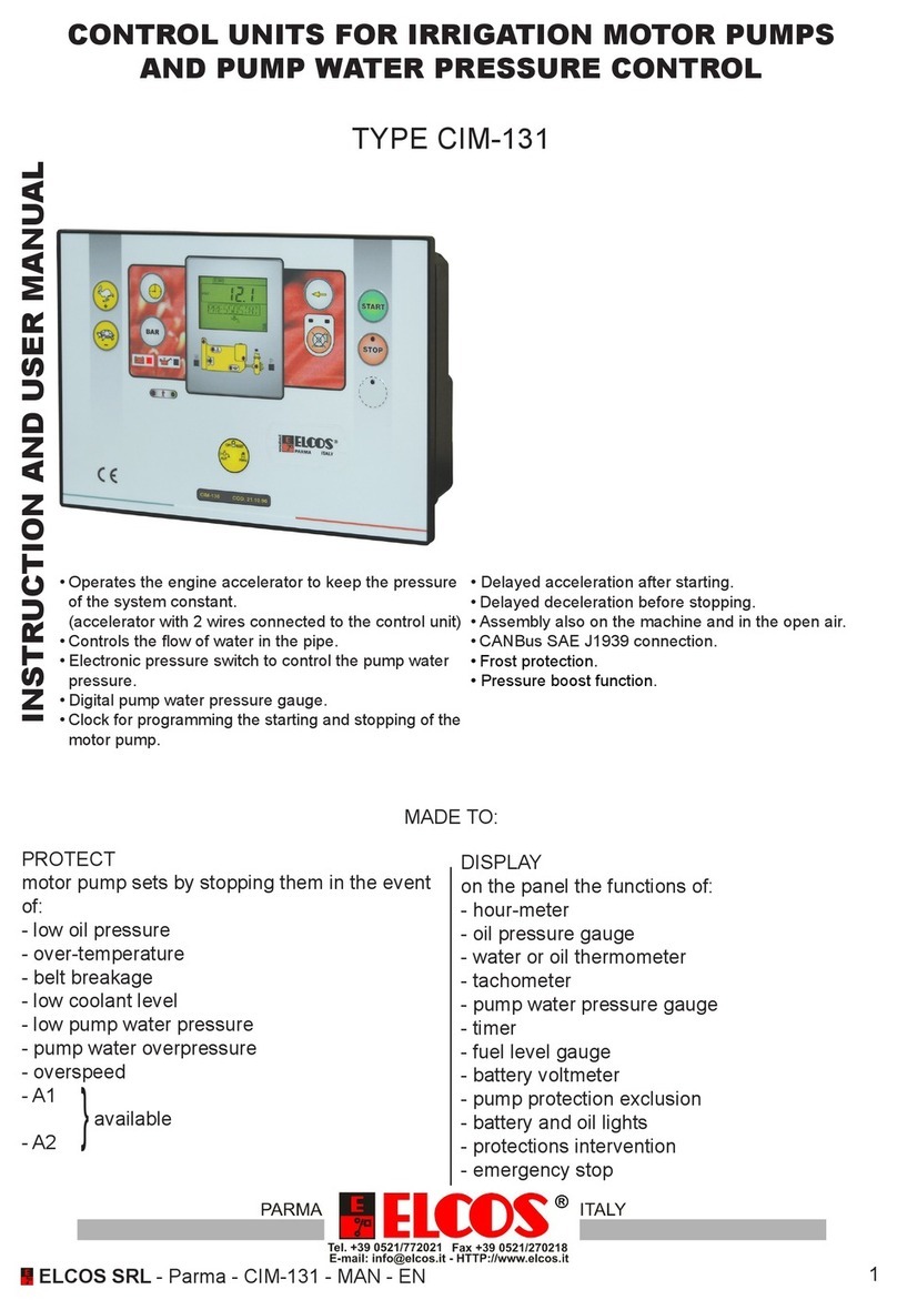
ELCOS CIM-131 Instruction Manual

ELCOS
ELCOS CIM-130 Instruction Manual
ELCOS
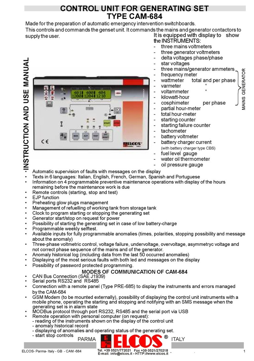
ELCOS CAM 684 User manual
ELCOS
ELCOS CEP-337 User manual
ELCOS
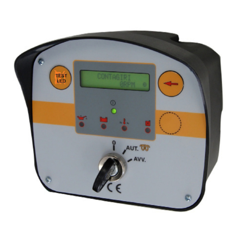
ELCOS CEP-090 User manual
ELCOS
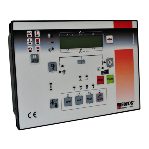
ELCOS CAM-685 User manual
ELCOS
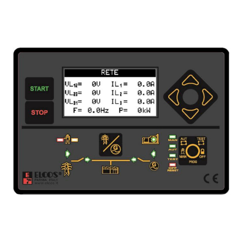
ELCOS CAM-335 User manual

ELCOS
ELCOS CIM-137/4G Instruction Manual
ELCOS
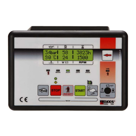
ELCOS DCA-120/10 Owner's manual
ELCOS
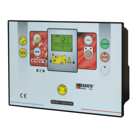
ELCOS CIM-137 Instruction Manual


