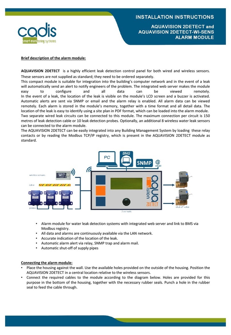
Cadis Aquavision Control User manual

User’s Manual
Aquavision Control
Monitoring Module
Contents
1. Introduction .................................................................................................................................... 2
2. Data and actions that are available without pasword .............................................................. 3
2.1. Real time data of the sanitary pipelines and water consumption .................................. 3
2.2 Acknowledging and checking alarms ................................................................................. 4
2.3. Consulting the list of alarms and creating alarm reports................................................. 5
3. Functions and configurations only available with pasword..................................................... 8
3.1. Making a connection with the module ................................................................................ 8
3.2. Modifying network settings .................................................................................................. 8
3.3. Connection with a CADIS Aquavision Master module .................................................... 9
3.4. Centralisation of consumption data by a central computer ............................................ 9
3.5. Modifying the password and user language ................................................................... 10
3.6. Alarm when daily or weekly consumption is exceeded ................................................. 10
3.7. Alarm during a period of no water consumption ............................................................ 11
3.8. Activation of special functions via relay contacts connected to the AV CONTROL module
11
3.9. Checking whether the module was correctly configured after installation ................. 12
3.10. ................... Setting alarm e-mail, cutting off water supply and buzzer per alarm type. 15
3.11. .......................... The calendar function: cut off or allow water supply with volume limit 16
3.12. ............................................. Configuration with water meter installed on the street side 17
3.13. ......................................................................................... Creation of consumption reports 18
3.14. .............................. Opening and closing the valves by the user via the control module 19
3.15. ................................................... Activating unlimited water consumption via the screen 19
4. ModBus communication ............................................................................................................. 20
5. Amending the IP address .......................................................................................................... 21

User’s Manual
Aquavision Control
Monitoring Module
1. Introduction
The Cadis AQUAVISON is a monitoring and control system that continuously measures, analyses and tracks a
building’s water consumption. Installing this system saves you a lot of water and avoids water damage caused by
leaks, creating an efficient and leak-free sanitation infrastructure. The Aquavision Control module in this system is a
registration and leak detection module, which is installed on the main sanitary pipeline. It constantly monitors the
flow in that main pipeline, detects a leak or waste and can automatically cut off the water supply in the event of
major problems to avoid water damage. One electrical shut-off valve is supplied as standard with the module, which
must be fitted on the main sanitary pipeline after the sub water meter. Two additional shut-off valves can be
installed on the branch pipelines (see diagram below). If additional branch pipelines need to be protected against
leaks and water wastage, a second Aquavision Control module must be fitted. For each additional module, three
extra branch pipelines can be protected.
To function properly, the Aquavision Control module must be connected to the pulse output of the sub water
meters that are installed in the separate pipelines in order to monitor consumption.
The touch screen on the module and the built-in web server allow all data and alarms to be followed up on site or
remotely via the network. Alarms and consumption data can be read out normally in a building management system
(BMS) via a ModBus network connection.
An ordinary user without a password can consult all the data on the module, see the alarms and also confirm active
alarms. A user who has a password and can log in can also modify the system parameters and create reports. The
standard user name and password on delivery for log-in are user/user
All the configurations described below can be carried both on the touch screen of the module as well as remotely on
a computer screen via the web browser.

User’s Manual
Aquavision Control
Monitoring Module
2. Data and actions that are available without pasword
The user can see the following data and carry out the following actions without firstly logging in with a password:
• consult the data
• confirm the alarms
• consult the alarm page with a summary of all alarms.
2.1. Real time data of the sanitary pipelines and water consumption
If you click in the main menu on the button "Real time data", a screen automatically appears with a summary of the most
important data:
Name of the module with the serial number
Date and time with the time of the last read-out
of the water meter underneath
The date is automatically correctly set if the
module is linked to a network with access to the
Internet.
Indication of the
consumption period and the
normal or alarm state of the
module.
Temperature and pressure data if fitted and
activated
Status of external systems that were
connected to this module.
In the table under the grey bars, the user can view the data for the various pipelines and water meters that have been installed.
The data include the pipe diameter, the serial number of the water meter and the name that the user can assign to the pipe.
All information about the shut-off valves per pipeline is
summarised in 2 columns. A green " " under
“Check” means that the automatic check of the valve
that the module itself conducted was successful. The
user can see whether the valve is open or shut and
thus whether the water supply is protected or not.
AV
-
CONTROL_HL_NL_02032017

User’s Manual
Aquavision Control
Monitoring Module
Note: To counter problems with lime scale, the shut-off valve is closed and re-opened weekly; this action is
performed fully automatically and takes place when there is no consumption detected. During this action a check is
also performed to ensure that the shut-off valve is fully closed. If the check of the valve has been conducted without
any problems, this value is OK (green ""). If the check of the valve has failed, then this value is 'error' (red "") and
the shut-off valve should be inspected.
The user can follow all detailed information about the water consumption per pipeline in the right-hand side of the
table. This information concerns the flow, consumption volume and the index of the water meter in m³.
2.2 Acknowledging and checking alarms
An alarm is always shown via a pop-up screen on the touch screen or in the web server page. In the special alarm
page a user with a password can also define the actions that must be linked to an alarm. Possible actions are:
sending an alarm e-mail, cutting off the water supply or activating a buzzer.
Each alarm must be acknowledged by the user, on the touch screen of the module, or remotely on a computer by
clicking the red button. For some alarms with very high consumption, it may be necessary to click
several times to acknowledge. The alarm confirmation time is saved in the module. If you want to acknowledge an
alarm remotely via your computer, you need access to the network to which the control module has also been
linked.
Given that the module constantly adjusts its values to the demands of the building, for certain alarms (very high
values) the user will need to indicate whether it relates to a normal, but high consumption, or whether a leak or
water wastage has indeed occurred. To do so, the user needs to click on the red "Alarm" button when there is a
real alarm or leak, or he must click on the green "False alarm" button if normal, yet high consumption is involved.
The module itself adapts the values for possible alarms after this last action and in the future no alarm will report
for the same consumption values.

User’s Manual
Aquavision Control
Monitoring Module
Once the problem has been solved, the user must restart the system by pressing on the red "System restart"
button. The valves that have automatically cut off the water supply will then be automatically re-opened.
N.B.: If you closed a valve manually, you must firstly manually open that valve before you restart the system (see
the instructions later in the manual).
The user can do the restart on the touch screen of the module or remotely via a computer on the same network.
The Aquavision Control Module will then resume normal operation and this is shown by the message 'System
normal".
2.3. Consulting the list of alarms and creating alarm reports
To be able to analyse several alarms that have occurred, the user can view a summary of all alarms on a separate
alarm page. In the main menu select the 'Alarm list" button.
This takes the user to a screen with all the detailed information about the alarms. This screen shows the type of
alarm and when it occurred, the time when the alarm was confirmed and also the time that the problem was solved
and the module was restarted. If it concerned a false alarm, this will be indicated with a "" in the column
concerned. Additional detailed information and comments can be added per alarm by a technician by pressing on
the button. On this detail screen, comments can be added at the bottom about the leak or the repair so that
these are available to everyone:

User’s Manual
Aquavision Control
Monitoring Module
On the same alarm screen, the user can easily create alarm reports for a particular period in order to get a better
insight into the alarms or to inform colleagues. This can be done by choosing a start date (click on "From") and end
date (click on "To") and then confirming that this period is correct and that you want to create a report.
Below is a list of possible alarm reports:
Large leak alarm Leak alarm for very large leak e.g. burst pipe
Leak Leak alarm detected that was calculated by the module
Small leak Module detected a small leak
Very small leak Leak alarm for a micro leak (alarm after 24 hours)
Average daily
consumption exceeded
(%)
Alarm report if the daily water consumption is higher than the average
daily consumption + the percentage that you have defined
Average weekly
consumption exceeded
(%)
Alarm report if the weekly water consumption is higher than the
average weekly consumption + the percentage that you have defined
Volume restriction Alarm if the volume, which is set by the user, has been reached,
Alarm leak detection
external system
Alarm report if the external leak detection system sets off an alarm
Valve malfunction Alarm if the functional test with the shut-off valve fails.

User’s Manual
Aquavision Control
Monitoring Module
Flow detected with valve
closed Alarm if the valve can no longer fully close
Unstable pressure
measured with valve
closed
Alarm if a loss of pressure is measured when the shut-off valve is
closed. This can indicate a very small leak in the pipe.
Alarm period no
consumption
Alarm report that can indicate a faulty connection with the water
meter.
Water pressure out of
range of pre-set limits
Alarm signal when the pressure exceeds or falls below the pre-set
minimum or maximum limits
Temperature out of
range of pre-set limits
Alarm signal when the temperature exceeds or falls below the pre-set
minimum or maximum limits
Unlimited water
consumption activated Report if the "Unlimited water consumption" mode is activated.
Manual valve closure
Report if a valve is closed by the user via a manual activation on the
module screen
Intrusion alarm active Report if the intrusion alarm was activated
Alarm main water pipe Report when a leak is observed between the street and the building.

User’s Manual
Aquavision Control
Monitoring Module
2. Functions and configurations only available with pasword
After installing this module, the sanitary installer has correctly set the basic functions such as pipe diameters, pulse
settings for the water meter, water meter ID, etc. in order to start the module. This is described in separate
installation instructions.
A user with a password can check these settings and modify them as required by logging in with his computer and
following this user's manual. For that purpose, the user must make a connection by means of his web browser with
the web server of the AV Control module. He can do this also via the touch screen of the module.
3.1. Making a connection with the module
To configure and enter the correct settings in the module a connection must be established by your computer with
the AV CONTROL module. For this reason both your computer and the AV CONTROL module must be linked either
directly or via a LAN network of the building on the LAN port. After this an Internet browser must be opened and
the pre-set IP address of the module must be entered in the address bar at the top of the browser:
10.100.100.225
N.B.: To do that the computer must be set in the same IP range. Otherwise no connection can be set up with the
module (see the information at the end of this document on how to adjust the range of your computer). When the
module and the computer are directly connected without using a network, a "crossed" LAN network cable must
always be used.
3.2. Modifying network settings
First of all, check whether the configuration of the module is correctly carried out. The module will only work
correctly if the installer has configured it correctly.
Log in as a user with user/user.
After logging in, a screen appears with the following headings. Click here on the "Configuration" button.
A screen then appears automatically with the Network settings. Check these network settings and amend the data
as necessary for the building in which the module was installed. Always consult a network specialist first for this to

User’s Manual
Aquavision Control
Monitoring Module
ensure that you are entering the correct data. Both the network settings of the actual module, and the e-mail
addresses for sending alarms can be set or changed in this screen.
N.B.: If you change the IP address, you must connect with the module via this new IP address. If the wrong data are
entered, this can cause problems with the connection.
2.3. Connection with a CADIS Aquavision Master module
At the bottom of the Network settings page, you can also enter an IP address for the Aquavision MASTER module.
N.B.: This should only be done if a CADIS MASTER module has been installed, which centralises all consumption
data. If not, leave this blank.
2.4. Centralisation of consumption data by a central computer
With this module it is also possible to monitor the water consumption of several buildings centrally via a central
server. If this is the case for this module, the IP address of this central server must be entered in the screen below.
Contact Cadis for additional information about this functionality.

User’s Manual
Aquavision Control
Monitoring Module
2.4. Modifying the password and user language
Go to the Device settings:
The user password can be changed here. Note it down and check it first and click on save to change it. Now you can
only log in using your new password. 'User' is then no longer valid.
On this page the user language and the name + the place of the module can be set or modified.
2.5. Alarm when daily or weekly consumption is exceeded
Go to the Device settings (same screen as above)
On the Device settings page a percentage can be entered in excess of the average day usage. The module will send
an alarm or cut off the water supply if the consumption in a day is higher than the average consumption + this
percentage. The same can be done per week. The type of alarm (alarm e-mail or water supply cut-off) is set on the
Alarm configuration page (see later).

User’s Manual
Aquavision Control
Monitoring Module
2.6. Alarm during a period of no water consumption
On the same "Device settings" page as above, it is possible to set whether you want to receive an alarm or even
want to cut off the water supply if during a set period no water consumption is measured. Setting this alarm has 2
functions depending on the building's situation:
1. No water consumption is measured during a fixed period in a building in which water is used. This means
that the water meter is defective or that a connection with the control module is damaged. Check this and
solve the problem.
2. In a vacant building, this function can automatically shut off the water supply so that no water damage can
occur. By installing a separate switch for unlimited water consumption and activating it, a user can use
water in a vacant building if necessary without a problem being reported.
2.7. Activation of special functions via relay contacts connected to the AV CONTROL module
The following special functions can be activated:
Connect external leak detection system to the AV Control module to cut off water supply or to send alarms.
Activate unlimited water consumption for a set period via external contact (for no more than 24 hours)
Link intrusion alarm system to the AV CONTROL module to stop the water supply.
The following functions can be activated in the Device settings screen (same as above):
If an additional leak detection system has been installed in the building, which works via leak sensors, the
alarm contact for this system can be connected to the AV Control module and this will then send out an
alarm e-mail or trigger an action if this external alarm contact switches. The type of action is defined in the
Alarm configuration screen. Tick () if an external leak detection system has been connected. (Closed
contact = External leak alarm)
If a large amount of water is regularly used in the building, e.g. for cleaning, the AV CONTROL module can
be temporarily switched off via an external contact. If the contact is switched on, the AV Control module
will be switched off until the contact is switched off. During the period of unlimited water consumption, the
following message appears on the module and in the web server:

User’s Manual
Aquavision Control
Monitoring Module
This function must only be ticked if this external contact for indefinite water consumption has been
installed. (Closed contact = indefinite water consumption activated)
To avoid water damage occurring in buildings where nobody is present, a relay contact can be linked via the
burglar alarm system to the AV CONTROL module. When the burglar alarm system is switched on, the AV
CONTROL module will automatically cut off the water supply by closing the shut-off valves. When the
burglar alarm system is switched off, the AV-Control module will re-open the water supply. The following
message appears on the screen and in the module when the burglar alarm is activated:
This function should only be ticked if an external contact for the burglar alarm system has been installed.
(Closed contact = Burglar alarm system activated)
2.8. Checking whether the module was correctly configured after installation
Go to the web page of the heading "Input settings"

User’s Manual
Aquavision Control
Monitoring Module
This brings you automatically to a screen showing the possible configurations of the module. On this module you
can connect the following water meters and protect pipelines against leaks:
1. Connect the pulse output for the distribution company's water meter. This allows the module to record
the official water consumption. This water meter is normally installed in the building. If this is not the
case and it is located on the street side, check point 3 below.
2. A sub water meter and accompanying shut-off valve, which are installed on the main water pipe just
before the collector with branch pipelines. This is therefore after any fire-fighting water supply branches
off (fire-fighting pipelines must never be shut off). This sub water meter and its accompanying shut-off
valve protect your entire sanitary pipe network. The AV Control module constantly analyses the water
consumption in this main sanitary pipeline and will automatically send out an alarm e-mail or even cut
off the water supply if problems arise. If this sanitary pipeline also supplies the water for fire hoses,
then no shut-off valve may be fitted.
3. Connect the water meter that was installed by the distribution company on the street side far from the
building. To protect the section of water pipe between the street side and the building, a sub water
meter is installed in the building on the main water pipe (this then replaces the official water meter
mentioned in point 1).
4. A maximum of 2 additional water meters and their accompanying shut-off valves can be installed on
branch pipelines of the collector. This affords selective protection for these pipes.
These water meters may also be installed on a rainwater pipe or a grey water pipe. Thus these pipes can
also be protected against leaks and water wastage.
5. A temperature and pressure sensor can also be installed on a pipeline of your choice and the AV Control
module can record these values. You will receive alarms if the values exceed or fall below the set limits.
The general configuration is shown in the diagram below (in this any water meter on the street side is not shown).
All connected water meters must be shown as active in the above-mentioned screen. If they have not been
installed, you must uncheck them and they will no longer be shown in the real-time screen.

User’s Manual
Aquavision Control
Monitoring Module
Check whether the installation of pipelines and water meters matches the configuration made by the installer on
the module. Only the installed water meters can be shown as active in the screen. You can change the data, line
by line, by clicking on the pencil on the right.
If you click on the pencil on the right, the next screen opens where you can amend the data per pipe:
The ID of the water meter and the name of the pipe can be filled in or changed here.
Check whether or not the water meter has been installed in the corresponding pipe and click to set it to Active
or Non-active (if a water meter has been installed on the street side, that too should be set to Active)
Adjust the total of the water meter index appropriately so that the values correspond.

User’s Manual
Aquavision Control
Monitoring Module
Check the value of the pulse output of the water meter (number of litres consumed per pulse) Watch out
because the point acts as a comma. Three digits are added automatically after the point. So if you fill in 1, this
automatically becomes 1.000
Check whether the diameter of the pipe matches the real diameter of the pipe. Select the correct DN size from
the table.
If a temperature or pressure sensor has been fitted, then these too must be set to Active. You can do this by clicking
on the pencil on the right and also set limits for the alarms.
2.9. Setting alarm e-mail, cutting off water supply and buzzer per alarm type.
You can insert the addresses to which alarm e-mails must be sent to in the Network settings page (see above).
Per alarm type you can choose whether you only want to have an alarm e-mail, and/or whether the valve for the
water supply must be closed and/or the buzzer on the module must be activated. For that go to the
Configuration/Alarm configuration screen.
On this screen, for each alarm type, you must click on the required action: Alarm e-mail, valve closed or buzzer on
alarm. Green is Active and red is Non-active. Please be very careful when deciding when the water supply is to be
shut off or not. Generally this is only set to “Active” for a large leak.

User’s Manual
Aquavision Control
Monitoring Module
The text of the alarm report that the user receives can also be modified, if wished, by pressing on the button.
The following screen appears:
The text of the error message concerned that
appears in the alarm e-mail can be
personalised here.
2.10. The calendar function: cut off or allow water supply with volume limit
By activating this function, the AV Control module will turn on or cut off water at pre-set times for predefined
pipelines. You can also decide to allow unlimited water or no water at all during certain times/periods.
This can all be set on the Configuration/Calendar screen:
To set new calendar functions you must always click on the blue function button "Add new". Each time you enter a
new schedule you must not forget to click on "Save":

User’s Manual
Aquavision Control
Monitoring Module
In addition to the programmable time schedule (From –To), you can also, if desired, set a water volume limit for this
period and also an alarm report if this volume limit is about to be reached. You can also choose to shut off the valve
if the volume limit has been reached by selecting the field "Close valve".
You must always indicate - per time period - which type of function you are choosing: this can be Normal (therefore
normal protection mode) with a volume limit as described above. However it can also be: No water supply during
that time period or Indefinite water consumption during that period. You can set this with the option button after
"Function". Don't forget to indicate each time which pipeline is involved. (option button after "Input")
Note: The time period can never be longer than 1 week. A week starts at the earliest on Monday and finishes at the
latest on Sunday.
The existing calendar settings can be removed by pressing on the button. They can be modified by pressing on
the button.
2.11. Configuration with water meter installed on the street side
The Aquavision Control module can also be used to monitor a water pipe where the distribution company water
meter is installed on the street side and there is a long supply pipe to the building that could leak. In this case a sub
water meter must be installed in the building. In this configuration the Aquavision Control module will monitor the
total measured volume of both meters (the water meter on the street side and the sub water meter on the main
pipe in the building) and report possible leaks in the supply pipe.
The settings can be defined in the "Configuration/Water meter street side" screen:

User’s Manual
Aquavision Control
Monitoring Module
The consumption on both water meters will be compared and the following settings should be made:
Periods of comparison (hrs): period over which the consumption values must be compared expressed
in hours. Set to 24 hours as standard. (Observation: when this is set to 0, the values are not
compared.
% permitted deviation: Percentage of deviation in consumption between both meters above which an
alarm report must be generated. (Set to 10% as standard)
2.12. Creation of consumption reports
All consumption data, alarms and actions are saved in the module for 1 year and can be consulted at any time. Via a
separate screen, the user can easily create consumption reports for chosen periods. Select the "Reports" screen in
the main menu at the top and the following overview appears:
To generate a report you need to select a desired period by clicking on the date field on the left. You do, however,
first need to select the correct pipe, in the field on the right, for which you want to create the report.
After clicking on "Confirm", the data for the requested period per day will appear on the screen.

User’s Manual
Aquavision Control
Monitoring Module
To download these data, press the "Download report" button. Next, select the file format. You can then further
process the data as you wish.
2.13. Opening and closing the valves by the user via the control module
The user can always manually operate the shut-off valves - after entering the password - via the touch screen of the
module or remotely via his computer.
If the user closes one or more valves via the screen of the AV-Control module, he must also manually open
them afterwards using the same procedure!
In the Real Time screen select the "User action" button
This brings you to a screen where you see the name of the pipe and also the status of the valve (Open (green) or
Closed (red)).
Press the button and you will see this symbol appear in
the Valve status column. This means that the valve is opening or closing. Afterwards the colour that indicates the
open or closed status of the valve changes. If the valve has been manually closed, it must then be manually opened
via this procedure so that the system can then function normally after that.
2.14. Activating unlimited water consumption via the screen

User’s Manual
Aquavision Control
Monitoring Module
The user can use unlimited amounts of water for a restricted period. This can be activated via the module touch
screen or remotely via his computer.
In the Real Time screen in the main menu select the "User action" button.
This takes you to a screen where you see the name of the pipe. In the column "Unlimited water consumption" press
on the "Active" button to activate unlimited water consumption.
This period of unlimited water consumption is restricted to 24 hours. The remaining time is also shown on the Real
time screen. As soon as this period of unlimited water consumption expires, the module will switch back again to
the normal protection mode.
Press the "Stop Unlimited water consumption" button to return to normal operation.
3. ModBus communication
This information is only intended for persons who set up and program the GBS systems.
The following data can be read by a GBS system by means of a ModBus TCP/IP communication protocol on the
standard IP port 502. Modbus RTU via RS485 can be used on slave address 1. This is fixed and cannot be changed. If
the communication takes place via Modbus RTU, the slave address is always 1. ( Baudrate = 19200 / Parity = None /
Bytesize = 8 / Stopbits = 1)
Register 30001 Street side water meter Total Low Word
Register 30002 Street side water meter Total High Word
Register 30003 Street side water meter Current flow Low word
Register 30004 Street side water meter Current flow High word
Register 30007 Official Water meter Total Low Word
Register 30008 Official Water meter Total High Word
Register 30009 Official Current flow water meter Low word
Register 30010 Official Current flow water meter High word
Register 30013 Sub Water meter 1 Total Low Word
Register 30014 Sub Water meter 1 Total High Word
Register 30015 Sub water meter 1 Current flow Low word
Register 30016 Sub water meter 1 Current flow High word
Table of contents
Other Cadis Control Unit manuals