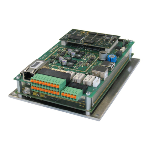
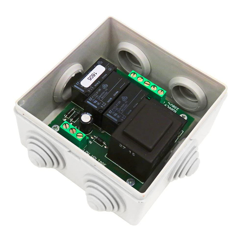
Seav LRX 2329 User manual

LRX 2329 NEW


CENTRALE ELETTRONICA LRX 2329
Centrale elettronica monofase, per l’automazione di serrande avvolgibili, ba-
sculanti e portoni con ricevente radio incorporata per l’attuazione di comandi
impartiti tramite Pulsantiera e Radiocomando.
- Mod. LG 2329 : Senza radio Ricevente
- Mod. LRS 2329 : 433,92 Mhz
- Mod. LRS 2329 SET : 433,92 Mhz narrow band
- Mod. LRH 2329 : 868,30 Mhz narrow band
importante per l’utente
- Il dispositivo può essere utilizzato da
bambini di età superiore a 8 anni o da
persone con ridotte capacità psico-fisi-
che o con poca conoscenza ed esperien-
za solamente se supervisionati o istruiti
sul funzionamento e le modalità di utiliz-
zo in maniera sicura per capire anche i
pericoli coinvolti nel suo utilizzo.
- Queste istruzioni, ed il testo completo
della dichiarazione di conformità UE è
disponibile al seguente indirizzo Inter-
net: http://www.seav.it
- Non consentire ai bambini di giocare
con il dispositivo e tenere lontano dalla
loro portata i radiocomandi.
- Esaminare frequentemente l’impianto
per rilevare eventuali segni di danneg-
giamento. Non utilizzare il dispositivo
se è necessario un intervento di ripa-
razione.
- Ricordarsi sempre di togliere l’alimen-
tazione prima di effettuare operazioni
di pulizia o manutenzione.
- Le operazioni di pulizia e manutenzione
non devono essere eseguite da bambini
senza essere supervisionati.
attenzione:conservare questo manua-
le d’istruzioni e rispettare le importanti
prescrizioni di sicurezza in esso contenu-
te. Il non rispetto delle prescrizioni po-
trebbe provocare danni e gravi incidenti.
I
3

4
importante per l’installatore
1) Prima di automatizzare il serramento è
necessario verificarne il buono stato, in
rispetto alla direttiva macchine e alla
conformità EN 12604.
2) Controllare che la locazione in cui è si-
tuata l’installazione consenta il rispetto
dei limiti di temperatura di esercizio in-
dicata per il dispositivo.
3) La sicurezza dell’installazione finale e il
rispetto di tutte le prescrizioni normati-
ve (EN 12453 - EN 12445) è a cura di
chi assembla le varie parti per costruire
una chiusura completa.
4) Usare dispositivi di sicurezza in grado di
monitorare lo stato della loro connes-
sione alla centrale elettrica.
5) Si consiglia, terminata l’installazione, di
eseguire tutti i controlli necessari (pro-
grammazione opportuna della centrale
e corretta installazione dei dispositivi
di sicurezza) per assicurarsi di aver ese-
guito un’installazione conforme.
6) Fissare la centrale ad una parete, ser-
vendosi, per il montaggio, dell’apposi-
to supporto di cui è dotato l’involucro,
in modo tale da lasciare tale supporto
verso il basso ed inserire delle viti di fis-
saggio negli appositi spazi.
7) La centrale non presenta nessun tipo
di dispositivo di sezionamento della li-
nea elettrica 230 Vac, sarà quindi cura
dell’installatore prevedere nell’impian-
to un dispositivo di sezionamento. E’
necessario installare un interruttore
omnipolare con categoria III di sovra-
tensione. Esso deve essere posizionato
in modo da essere protetto contro le
richiusure accidentali secondo quanto

5
previsto al punto 5.2.9 della EN 12453.
8) I cavi di alimentazione e di collega-
mento motore idonei per inserimen-
to sui pressacavi pg9 forniti devono
avere diametro esterno compreso tra
4,5 e 7 mm. I fili conduttori interni
devono avere sezione nominale pari
a 0,75mm2.. Se non viene utilizzata
una canalina, si raccomanda di usa-
re cavi di materiale H05RR-F Prestare
attenzione a fissare i cavi in modo che
siano ancorati in modo stabile.
Fare attenzione inoltre, in fase di fo-
ratura dell’ involucro esterno per far
passare cavi di alimentazione e di col-
legamento, e di assemblaggio dei pres-
sacavi, ad installare il tutto in modo da
mantenere il più possibile inalterate le
caratteristiche di grado IP della scatola.
9) Il motoriduttore usato per muovere il
serramento deve essere conforme a
quanto prescritto al punto 5.2.7 della
EN 12453.
10) In accordo al 5.4.2 della EN 12453 è
consigliabile usare motoriduttori dotati
di un dispositivo di sblocco elettromec-
canico, per consentire in caso di neces-
sità, di muovere il serramento manual-
mente.
11) Inaccordo al5.4.3. dellaEN 12453utiliz-
zare sistemi di sblocco elettromeccani-
co o dispositivi similari che permettano
al serramento di arrestarsi in sicurezza
nella sua posizione di finecorsa
12) Il cablaggio dei vari componenti elet-
trici esterni alla centralina deve essere
effettuato secondo quanto prescritto
dalla normativa EN 60204-1 e dalle
modifiche a questa apportata dal pun-
to 5.2.7 della EN 12453. Il fissaggio dei

6
cavi di alimentazione e di collegamen-
to, deve essere garantito tramite l’as-
semblaggio di pressacavi.
13) L’eventuale montaggio di una pulsan-
tiera per il comando manuale deve es-
sere fatto posizionando la pulsantiera
in modo che l’utente non venga a tro-
varsi in posizione pericolosa.
14) La funzione di sicurezza garantita dal-
la centralina è attiva solo in chiusu-
ra; pertanto la protezione in apertu-
ra deve essere assicurata in fase di
installazione con misure (ripari o di-
stanze di sicurezza ) indipendenti dal
circuito di controllo.
15) Per un corretto funzionamento della
parte radio ricevente, in caso di utilizzo
di due o più centrali, si consiglia l’in-
stallazione ad una distanza di almeno 3
metri l’una dall’altra.
Il testo completo della dichiarazione di conformità UE è disponibile
al seguente indirizzo Internet: http://www.seav.it
CARATTERISTICHE TECNICHE:
- Alimentazione : 230 Vac 50-60Hz 900W (4A) max.
- Uscita lampeggiante : 230 Vac 50-60 Hz
100W Resistive Load max.
50W Inductive Load max.
- Uscita motore : 230 Vac 50-60Hz 750 W max.
- Uscita alimentazione servizi : 12 Vac 2 W max.
- Sicurezze e comandi in BT : 12 Vcc
- Temperatura d’esercizio : -10 ÷ 55 °C
- Ricevitore radio : vedi modello
- Trasmettitori op. : 12-18 Bit - Rolling Code - Plus
- N° dispositivi memorizzabili : 120 max.
- Dimensioni scheda : 100x105 mm.
- Dimensioni scatola : 110x121x47 mm.
- Contenitore : ABS V-0 ( IP54 ).
COLLEGAMENTI DELLA MORSETTIERA:
CN1:
1 : Ingresso linea 230 Vac (Fase).
2 : Ingresso linea 230 Vac (Neutro).
3 : Uscita Motore 230V Apertura.
4 : Uscita Motore 230V Comune.
5 : Uscita Motore 230V Chiusura.
6 : Uscita Lampeggiante 230 Vac (Neutro).
7 : Uscita Lampeggiante 230 Vac (Fase).
La Centrale Elettronica:
LG 2329 - LRS 2329
LRS 2329 SET - LRH 2329
sono conformi alle specifiche delle Direttive
RED 2014/53/EU, EMC 2014/30/EU, LVD 2014/35/EU.

7
CN2:
8 : Alimentazione Fotocellule ( 12Vac ).
9 : Alimentazione Fotocellule ( GND ).
10 : Ingresso Dispositivo Sicurezza (NC).
11 : Ingresso GND comune
12 : Ingresso Pulsante comando (NA).
CARATTERISTICHE FUNZIONALI:
Funzionamento Passo-Passo:
Utilizzando sia il Radiocomando che i pulsanti in bassa tensione per l’azionamento del serra-
mento, si otterrà il seguente funzionamento:
il primo impulso comanda l’apertura fino allo scadere del tempo motore o al raggiungimento
del fine corsa d’apertura, il secondo impulso comanda la chiusura del serramento; se si invia un
impulso prima dello scadere del tempo motore o del raggiungimento di uno dei due finecorsa,
la centrale effettua l’arresto del moto sia nella fase di apertura sia in quella di chiusura. Un
ulteriore comando determina la ripresa del moto in senso opposto.
Funzionamento con differenti modelli di radiocomandi:
E’ possibile la programmazione di differenti modelli di radiocomandi: memorizzando un
codice ( 1 tasto ) si ottiene un funzionamento ciclico Passo - Passo (Apertura - Stop -
Chiusura); memorizzando due codici ( 2 tasti ) differenti si ottengono dei comandi distinti,
il primo per l’Apertura ed il secondo per la Chiusura.
Funzionamento con radiocomando 1 Tasto:
Utilizzando il radiocomando con un solo tasto si ottiene il seguente funzionamento: il
primo impulso comanda l’Apertura fino allo scadere del tempo motore. Il secondo impulso
comanda la Chiusura del serramento; se un impulso perviene prima dello scadere del
tempo motore, la centrale effettua l’arresto del serramento, un ulteriore impulso effettua
la ripresa del moto nel senso opposto di marcia.
Funzionamento con radiocomando 2 Tasti:
Utilizzando il radiocomando con 2 tasti si ottiene il seguente funzionamento: il primo tasto
(“Up” associato al senso di apertura) comanda l’Apertura fino allo scadere del tempo
motore ed il secondo tasto ( “Down” associato al senso Chiusura ) comanda la Chiusura
del serramento. Nel caso in cui durante l’Apertura venga inviato nuovamente un comando
Up la centrale continua il moto di Apertura, mentre se ad essere inviato è un comando
Down la centrale effettua l’arresto del moto.
La stessa procedura è valida nella fase di Chiusura.
Chiusura automatica:
La centrale permette di richiudere il serramento in modo automatico senza l’invio di co-
mandi supplementari.
Dispositivo di Sicurezza (Fotocellule):
La centrale permette l’alimentazione ed il collegamento di Fotocellule, Coste pneuma-
tiche (NC).
- Ingresso DS (NC)
L’intervento del Dispositivo di Sicurezza nella fase di apertura non viene conside-
rato, nella fase di chiusura provoca l’inversione del moto.
Attenzione: questo ingresso se non utilizzato deve essere ponticellato.
SELEZIONE DELLE FUNZIONALITA’
La centrale è fornita dal costruttore con la possibilità di selezionare alcune funzioni importanti
tramite il Dip-Switch SW1 con conseguente accensione del led corrispondente.

8
------------ DIP SWITCH SW1 ------------
Riferimento Led Led spento Led Acceso
DIP 1 = T. PAUSA Senza chiusura aut. Con chiusura aut.
DIP 2 = PROG . T. MOTORE No Si
DIP 3 = UOMO PRESENTE No (Si ) *
DIP 4 = LAMP./CORT. Lampeggiante Luce di Cortesia
DIP 5 = P.P / INV. Passo – Passo Invertente
* La funzione Uomo Presente esclude automaticamente la richiusura automatica, quindi
con DIP 3 = ON è possibile selezionare Uomo Presente in Apertura e Chiusura (DIP 1 =
OFF) oppure Uomo Presente solo in Chiusura (DIP 1 = ON)
DIP 1 = T. PAUSA: (Prog. tempo chiusura aut. 4 min. max.)
La centrale è fornita dal costruttore con la funzione di chiusura automatica DIP 1 = ON e
temporizzatore ( default 15 sec. ) .
Se si desidera modificare il tempo di chiusura automatica,
a centrale ferma, procedere nel seguente modo: posizionare DIP 1 e DIP 2 = ON, preme-
re per un istante il pulsante di manovra o il tasto del Radiocomando precedentemente
programmato, la centrale emetterà tre segnali acustici di inizio programmazione, atten-
dere il tempo desiderato, poi inviare nuovamente un comando per un istante; la cen-
trale emetterà quattro segnali acustici di fine programmazione che determineranno la
memorizzazione del tempo di chiusura automatica, quindi riportare il DIP 2 = OFF per
concludere l’operazione.
Se invece si desidera non avere la funzione di richiusura automatica, posizionare il DIP
1 = OFF.
DIP 2 = PROG. T. MOT: (Prog. Tempo Motore 4 minuti max.)
La centrale è fornita dal costruttore con un tempo di lavoro motore predefinito pari a
30 sec.
Se si desidera modificare il Tempo di lavoro del Motore, solamente a centrale chiusa,
procedere nel seguente modo: posizionare DIP 2 = ON, premere per un istante il pulsan-
te di manovra o il tasto del Radiocomando precedentemente programmato, la centrale
emetterà tre segnali acustici di inizio programmazione, la centrale effettuerà l’apertura
del serramento, al raggiungimento della posizione desiderata premere nuovamente per
un istante, la centrale effettuerà l’arresto del serramento, la centrale emetterà quattro
segnali acustici che indicheranno la fine della programmazione, quindi riportare il DIP 2 =
OFF per concludere l’operazione.
DIP 3 = Funz. Uomo Presente AP/CH (DIP 1 = OFF):
La centrale è fornita dal costruttore con la funzione di Uomo Presente disabilitata.
Se si desidera abilitare la funzionalità Uomo Presente sia nella fase di Apertura che quel-
la di chiusura, a centrale ferma, posizionare DIP 3 = ON, in questo modo, per ottenere il
movimento del serramento, sarà necessario tenere premuto il pulsante del radiocomando
o quello di manovra per tutta la durata del moto.
Se si desidera abilitare il funzionamento ad Uomo Presente nella sola fase di Chiusura,
ripetere l’operazione sopra descritta, posizionando oltre al DIP 3 anche il DIP 1 = ON.
DIP 4 = LAMPEGGIANTE / LUCE CORTESIA
La centrale dispone di una uscita 230Vac, per il collegamento di un lampeggiante o di
una luce di cortesia.
La centrale è fornita dal costruttore con la funzione Lampeggiatore abilitata DIP 4 = OFF.
Se si desidera abilitare la funzionalità Luce di cortesia, a centrale ferma, posizionare
DIP 4 = ON
Funzionamento Lampeggiatore: L’uscita 230 Vac. si attiverà ogni volta che l’automa-
zione è in movimento, per la durata del tempo motore. Nel caso in cui sia memorizzato il
Tempo di Pausa, il lampeggiatore sarà attivo anche durante la Pausa.
Funzionamento Luce di Cortesia: L’uscita 230 Vac. si attiverà per la durata di 3 minuti,
ogni qualvolta che sarà impartito un comando di salita.
DIP 5 = PASSO - PASSO / INVERTENTE :
La centrale è fornita dal costruttore con il modo di Funzionamento Passo - Passo DIP
5 = OFF.
Se si desidera abilitare la funzionalità Invertente, a centrale ferma, posizionare DIP 5
= ON, in questo modo, si otterrà il seguente funzionamento: il primo impulso comanda
l’apertura fino allo scadere del tempo motore, il secondo impulso comanda la chiusura
del serramento, se si invia un impulso prima dello scadere del tempo motore, la centrale
effettua l’inversione del moto sia nella fase d’apertura sia in quella di chiusura.
Posizionare il DIP 5 = OFF se si desidera ripristinare la configurazione precedente.
SEGNALAZIONI SONORE
1 x Breve BIP = Primo codice radiocomando memorizzato
2 x Brevi BIP = Secondo codice radiocomando memorizzato
3 x Brevi BIP = Inizio fase di Progr. T. Mot./ T. Pausa/ RDC
4 x Brevi BIP = Fine fase di Prog. T. Mot./ T. Pausa/ RDC
-------------------------------------------------------------------------------------
1 x Lungo BIP = Radiocomando non memorizzabile
2 x Lunghi BIP = Reset dei radiocomandi
3 x Lunghi BIP = Reset dei tempi motore e pausa

9
PROGRAMMAZIONE DEI RADIOCOMANDI:
Programmazione del radiocomando 1 o 2 Tasti.
La programmazione dei codici di trasmissione del radiocomando è eseguita nel seguen-
te modo: premere il tasto PROG, la centrale emetterà tre brevi segnali acustici di inizio
programmazione, il LED CODE inizierà a lampeggiare, allo stesso tempo inviare il primo
codice ( “Up” associato al senso di apertura ) del radiocomando allo stesso tempo la
centrale emetterà un breve segnale acustico indicando l’avvenuta programmazione;
successivamente il LED CODE inizierà a lampeggiare velocemente: inviare il secondo
codice (“Down” associato al senso di chiusura) da memorizzare, il LED CODE rimarrà
acceso allo stesso tempo la centrale emetterà due brevi segnali acustici indicando
l’avvenuta programmazione.
Se non viene inviato il secondo codice entro 10 secondi la centrale esce dalla fase di
programmazione emettendo quattro brevi segnali acustici e selezionando il funziona-
mento con 1 tasto del radiocomando.
Programmazione del codice di trasmissione a distanza
(funzionante solamente con Radiocomandi serie Y17/19).
Questa procedura, consente la programmazione del codice di trasmissione, senza
intervenire direttamente sul tasto PROG della centrale, ma eseguendo l’operazione
a distanza.
La programmazione del codice di trasmissione a distanza, si esegue nel seguente
modo: premere il primo e il secondo tasto di un radiocomando precedentemente
memorizzato, per un tempo maggiore a 3 secondi, quindi, la centrale emetterà 3
brevi BIP di conferma; successivamente premere il tasto di normale funzionamento,
dello stesso radiocomando, per un tempo maggiore a 3 secondi, quindi, la centrale
emetterà altri 3 brevi BIP di conferma, infine premere il tasto del radiocomando da
memorizzare per un tempo maggiore di 3 secondi, la centrale invierà 4 brevi BIP,
segnalando l’uscita dal modo di programmazione a distanza.
Cancellazione dei Radiocomandi:
La cancellazione di tutti i Radiocomandi memorizzati si esegue nel seguente modo: pre-
mere il tasto PROG fino a quando la centrale non emetterà una serie di tre brevi e poi due
lunghi segnali acustici indicando l’entrata in programmazione e l’avvenuta cancellazione
di tutti i radiocomandi memorizzati. La centrale rimarrà in modalità programmazione per
circa 10 sec. poi uscirà autonomamente emettendo quattro brevi segnali acustici.
Numero massimo Radiocomandi memorizzabili:
La centrale permette di memorizzare fino a 120 Radiocomandi aventi codice diverso fra
loro. Nel caso in cui il numero massimo di Radiocomandi memorizzabili sia stato raggiun-
to, ripetendo l’operazione di programmazione, la centrale evidenzia il fallimento, effet-
tuando il mancato lampeggio del LED CODE che resta acceso fisso e emettendo un lungo
segnale acustico; successivamente la centrale invierà 4 brevi BIP, segnalando l’uscita dal
modo di programmazione.
RESET (solo dei Tempi Motore e Pausa):
Nel caso sia opportuno ripristinare tutti i tempi Motore e Pausa ai valori di fabbrica,
posizionare DIP 1, DIP 2, DIP 3, DIP 4 e DIP 5 in ON allo stesso premere il tasto PROG fino
a quando la centrale non emetterà una serie di tre brevi e poi tre lunghi segnali acustici in-
dicando l’entrata in programmazione e l’avvenuta cancellazione di tutti i Tempi memoriz-
zati, quindi riportare il DIP 1, DIP2 , DIP 3, DIP 4 e DIP 5 = OFF per concludere l’operazione.
DIAGNOSTICA:
Test input comandi:
In corrispondenza ad ogni ingresso di comando in bassa tensione, la centrale dispone di
un LED di segnalazione, in modo tale da poter controllare rapidamente lo stato.
Logica di funzionamento: LED acceso ingresso chiuso, LED spento ingresso aperto.
Rev. 1.4 04/05/2020

ELECTRONIC CONTROL UNIT LRX 2329
Single-phase electronic control unit for the automation of rolling shutters,
sliding doors and entrance doors with built-in radio receiver to launch the
controls transmitted via the Push-button Panel and Radio Control
- Mod. LG 2329 : Without radio receiver
- Mod. LRS 2329 : 433,92 Mhz
- Mod. LRS 2329 SET : 433,92 Mhz narrow band
- Mod. LRH 2329 : 868,30 Mhz narrow band
important for the user
- The device can be used by children over
8 years of age and persons with redu-
ced physical or psychological abilities
or with little knowledge and experience
only if supervised or educated in its ope-
ration and safe use, in order to also un-
derstand the dangers involved in its use.
- These instructions, and the full text re-
garding the EU Declaration of Conformi-
ty is available from the following Inter-
net address: http://www.seav.it
- Do not allow children to play with the
device and keep the remote controls out
of their reach.
- Frequently examine the system to detect
any signs of damage. Do not use the de-
vice if it is in need of repair work.
- Always remember to disconnect the po-
wer supply before carrying out any clea-
ning or maintenance.
- Cleaning and maintenance must not be
carried out by unsupervised children.
attention:keep this instruction manual
safe and observe the important safety
requirements contained herein. Failure
to comply with the requirements may
cause damage and serious accidents.
importante per l’installatore
1) Before automating the fixture, check
that it is in good condition, in com-
GB
10

11
pliance with the Machinery Directive
and with EN 12604.
2) Check that the location where the
installation is located enables com-
pliance with operating temperature
limits specified for the device.
3) The safety of the final installation
and compliance with all prescribed
Standards (EN 12453 - EN 12445) is
the responsibility of the person who
assembles the various parts to con-
struct a total closing.
4) Use safety devices capable of moni-
toring the status of their connection
to the electrical control unit.
5) Once installation is finished, it is
recommended that all necessary
checks be performed (appropriate
programming of the control panel and
correct installation of safety devices)
to ensure that compliant installation
has been performed.
6) Fix the control unit to a wall, using
the relevant support which is fitted to
the casing, in such a way as to leave
said support facing downwards and
insert the fixing screws in the specific
holes.
7) The control unit does not have any
type of disconnecting device for the
230 Vac line. It is therefore the re-
sponsibility of the installer to set up
a disconnecting device inside the sy-
stem. It is necessary to install an om-
nipolar switch, surge category III. It
must be positioned to provide protec-
tion from accidental closing, pursuant
to point 5.2.9 of EN 12453.
8) Cables for power and connection to
the motor suitable for insertion in the

12
pg9 cable glands provided must have
an outside diameter between 4.5 and
7 mm. The internal conductor wires
must have a nominal cross-section
of 0.75mm2. If a raceway is not used,
use H05RR-F cables. Pay careful at-
tention when fastening the cables
so that they are anchored in a stable
manner.
Furthermore, care is required when
drilling holes in the outside casing
where connecting and power sup-
ply cables will pass, and when as-
sembling the cable glands, so that
everything is installed so as to main-
tain the panel’s IP protection cha-
racteristics.
9) The gear motor used to move the
fixture must comply with the require-
ments of point 5.2.7 of EN 12453.
10) In compliance with 5.4.2 of EN 12453,
it is recommended to use gear motors
equipped with an electrical-mechani-
cal release device, so that the fixture
can be moved manually in case of ne-
cessity.
11) In compliance with 5.4.3. of EN 12453,
use electrical-mechanical release sy-
stems or similar devices which stop the
fixture safely in the end run position.
12) The various electrical components
external to the control unit must be
wired in accordance with standard
EN 60204-1 as amended, and as set
forth in point 5.2.7 of EN 12453. The
fixing of power and connection cables
must be secured through the use of
cable glands.
13) The assembly of a push button panel
for manual control must be comple-

13
ted positioning the push button panel
in such a way that the user is not pla-
ced in a dangerous position.
14) The safety function ensured by the
control unit is active only during clo-
sing, therefore, protection on opening
must be ensured in the installation
phase with measures (guards or sa-
fety distances) independent from the
control circuit.
15) For proper functioning of the radio
receiver, if using one or more control
units, the installation at a minimum
distance of at least 3 metres one from
the other is recommended.
The full text regarding the EU Declaration of Conformity is available
from the following Internet address: http://www.seav.it
TECHNICAL DATA:
- Power supply : 230 Vac 50-60Hz 900W (4A) max.
- Flashing light output : 230 Vac 50-60 Hz
100W Resistive Load max.
50W Inductive Load max.
- Motor output : 230 Vac 50-60Hz 750 W max.
- Services power supply output : 12 Vac 2 W max.
- Safety devices and controls in BT : 12 Vcc
- Operating temperature : -10 ÷ 55 °C
- Radio receiver : see model
- Op. transmitters : 12-18 Bit - Rolling Code - Plus
- No. of devices that can be stored : 120 max.
- Board dimensions : 100x105 mm.
- Dimensions of container : 110x121x47 mm.
- Container : ABS V-0 ( IP54 ).
TERMINAL BOARD CONNECTIONS:
CN1:
1 : 230 Vac line input (Phase)
2 : 230 Vac line input (Neutral)
3 : Opening 230V Motor Output
4 : Common 230V Motor Output
5 : Closing 230V Motor Output
6 : 230 Vac Flashing light Output (Neutral)
7 : 230 Vac Flashing light Output (Phase)
CN2:
8 : Power supply to photocells (12 Vac)
9 : Power supply to photocells (GND)
10 : Safety device input (NC)
11 : Common GND input
12 : Control button input (NA)
The electronic control unit:
LG 2329 - LRS 2329
LRS 2329 SET - LRH 2329
they comply with the specifications of the Directives
RED 2014/53/EU, EMC 2014/30/EU, LVD 2014/35/EU.

14
OPERATING CHARACTERISTICS:
Step-by-step operation:
By using either the Radio Control or the low voltage buttons to activate the fixture, you
obtain the following action:
the first impulse activates the opening mechanism until the motor time expires or the
opening limit switch is reached, the second impulse closes the fixture. If an impulse is
sent before the motor time expires or one of the two end runs are reached, the control
unit will stop both opening and closing movements. An additional control re-starts motion
in the opposite direction.
Operation with different radio control models:
Different radio control models can be programmed: store one code (1 key) for Step-by-
Step cyclic operation (Opening - Stop - Closing); store two different codes (2 keys) for
separate controls, the first for Opening and the second for Closing.
Radio control operation with 1 Key:
Using the radio control with only one key, the following function is obtained: the first
impulse commands Opening until the motor time expires. The second impulse commands
Closing of the fixture. If an impulse occurs before the motor time expires, the control
unit stops the fixture. A further impulse implements the re-starting of the motion in the
opposite direction.
Radio control operation with 2 Keys:
Using the radio control with 2 keys, the following function is obtained: the first key (“Up”
associated to the Opening direction) commands Opening until the motor time expires,
and the second key (“Down” associated to the Closing direction) commands Closing of
the fixture. If the Up command is given again during Opening, the control unit continues
the Opening motion, while if a Down command is given, the control unit stops motion.
The same procedure is valid during the Closing phase.
Automatic closing:
The control unit closes the fixture automatically without sending additional commands.
Safety Device (Photocells):
The control unit allows for the connection and control of Photocells, Pneumatic
edges (NC).
- DS Input (NC)
Commands from the Safety Device are ignored during opening, whereas during
closing they will reverse the direction of movement.
Attention: if not used this input must be jumped.
SELECTING THE FEATURES
The control unit is supplied by the manufacturer with the option of selecting important
features via DIP switch SW1, which causes the corresponding LED to turn on.
------------ DIP SWITCH SW1 ------------
Riferimento Led Led spento Led Acceso
DIP 1 = T. PAUSE Without aut. closing With auto close
DIP 2 = MOTOR T. PROG . No Yes
DIP 3 = OPERATOR PRESENT No (Yes )*
DIP 4 = LAMP./CORT. Flashing Courtesy Light
DIP 5 = P.P / INV. Step-by-Step Inverting
* The Operator Present function automatically excludes automatic reclosing, therefore
with DIP 3 = ON it is possible to select Operator Present during Opening and Closure
(DIP 1 = OFF) or Operator Present only during Closure (DIP 1 = ON)

15
DIP 1 = T. PAUSE: (Aut. closing time prog. max. 4 minutes)
The control unit is supplied by the manufacturer with the automatic closing feature DIP 1
= ON and timer (default 15 sec.).
Proceed as follows to change the automatic closing time with the control unit stopped:
set DIP 1 and DIP 2 = ON, briefly press the operating button or the Radio Control key pro-
grammed earlier. The control unit will emit three acoustic signals to launch the program-
ming. Wait for the desired time, then send a command again for a moment. The control
unit will emit four acoustic signals at the end of programming meaning the automatic
closing time is being saved. Then go back to DIP 2 = OFF to end the operation.
If instead you do not want the automatic closing feature, set DIP 1 = OFF.
DIP 2 = MOT T. PROG.: (Motor Time Prog. max. 4 minutes)
The control unit is supplied by the manufacturer with a working time motor predefined
equal to 30 sec.
Proceed as follows to change the work Time of the Motor, only with the control unit clo-
sed: set DIP 2 = ON, briefly press the operating button or the Radio Control key program-
med earlier. The control unit will emit three acoustic signals to launch the programming,
the control unit will open the door and when it reaches the desired position briefly press
again. The control unit will stop the door and emit four acoustic signals that indicate the
end of programming. Then go back to DIP 2 = OFF to end the operation.
DIP 3 = Operator Present Feature AP/CH (DIP 1 = OFF):
The control unit is supplied by the manufacturer with the Operator Present Function di-
sabled.
To enable the Operator Present feature in both the Opening and Closing phases, with
the control unit stopped, set DIP 3 = ON to move the fixture. Hold down the radio control
button or the operating button for the duration of the movement.
To enable the Operator Present function for the closing phase only, repeat the operation
described above and set both DIP 3 and DIP 1 = ON.
DIP 4 = FLASHING / COURTESY LIGHT
The control unit has a 230 Vac output, for connection to a flashing light or a courtesy light.
The control unit is supplied by the manufacturer with the Flashing function enabled DIP
4 = OFF.
To enable the Courtesy light feature, with the control unit stopped, set DIP 4 = ON.
Flashing Light feature: The 230 Vac output will be activated each time the automation
is moving, for the duration of the motor time. If the Pause Time is saved, the flashing light
will be on during the Pause as well.
Courtesy Light Function: The 230 Vac output will be activated for 3 minutes, each time
that an ascent command is given.
DIP 5 = STEP-BY-STEP / INVERTING:
The control unit is supplied by the manufacturer with the Step-by-step mode DIP 5 = OFF.
To enable the Inverting feature, with the control unit stopped, set DIP 5 = ON. This way,
you will obtain the following operation: the first impulse controls opening until the motor
time expires, the second impulse controls fixture closing. If an impulse is sent before the
motor time expires, the control unit changes the direction of motion in the opening
and closing phases.
Set DIP 5 = OFF to restore the previous configuration.
SOUND SIGNALS
1 x Short BEEP = First remote control code saved.
2 x Short BEEPS = Second remote control code saved
3 x Short BEEPS = Start of Mot.T. Progr. / Pause T. / RDC
4 x Short BEEPS = End of Mot.T. Progr. / Pause T. / RDC
-------------------------------------------------------------------------------------
1 x Long BEEP = Radio control cannot be saved
2 x Long BEEPS = Reset of radio controls
3 x Long BEEPS = Reset of motor and pause time
PROGRAMMING OF RADIO CONTROLS:
Programming the radio control with 1 or 2 Keys.
Radio control transmission codes are programmed as follows: press the PROG button,
the control unit will emit three short beeps to launch the programming. The CODE LED
will start flashing and at the same time it will send the first code (“Up” associated with
the opening direction) of the radio control. At the same time, the control unit will emit a
short acoustic signal indicating that programming has been completed. Then the CODE
LED will start flashing quickly: send the second code (“Down” associated with the closing
direction) to be saved. The CODE LED will remain on and at the same time the control unit
will emit two short acoustic signals indicating that programming has been completed.
If the second code is not sent within 10 seconds, the control unit will exit the program-
ming phase by emitting four short acoustic signals. Select the function with only 1 key
of the radio control.
Remote transmission code programming
(only works with Y17/19 series Radio Controls).
This procedure allows to program the transmission code remotely, without using the PROG
button on the unit itself, but remotely following the operation.
The long distance transmission code is programmed as follows: press the first and second keys

16
of a radio control saved earlier, for more than 3 seconds. The control unit will then emit 3
short confirmation BEEPS. Press the normal operation button of the same remote control
for more than 3 seconds, the control unit will emit another 3 short confirmation BEEPS.
Lastly, press the radio control button to be saved for more than 3 seconds, the control unit
will send 4 short BEEPS, thereby signalling the exit from the remote programming mode.
Deleting the Radio Controls:
Proceed as follows to delete all the Radio Controls saved: press the PROG button until the
control unit emits a series of three short and then two long acoustic signals, indicating
the launch of the programming stage and the deletion of all the radio controls saved. The
control unit will remain in programming mode for about 10 sec., after which it will exit
autonomously by emitting four short beeps.
Maximum number of remote controls that can be saved:
The control unit can save up to 120 Radio Controls with different codes. If the maxi-
mum number of radio controls that can be saved has been reached, by repeating the
programming operation, the control unit highlights the failure: the LED CODE does not
flash, remaining on steady and emitting a long acoustic signal. The control unit will then
send 4 short beeps, signalling the exit from the programming mode.
RESET (applies to Motor and Pause Time only):
If it is best to restore all the Motor and Pause times to the factory values, set DIP 1, DIP 2,
DIP 3, DIP 4 and DIP 5 to ON. At the same time, press the PROG key until the control unit
emits a series of three short and then three long acoustic signals, indicating the launch of
the programming and the deletion of all the times saved. Then set back DIP 1, DIP2, DIP
3, DIP 4 and DIP 5 = OFF to end the operation.
DIAGNOSTICS:
Control input test:
On each low voltage control input, the control unit uses an LED signal to make the status
readily known.
Operating logic: when an LED is on it means the input is closed, when an LED is off it
means the input is open.
Rev. 1.4 04/05/2020

CENTRALE ÉLECTRONIQUE LRX 2329
Single-phase electronic control unit for the automation of rolling shutters,
sliding doors and entrance doors with built-in radio receiver to launch the
controls transmitted via the Push-button Panel and Radio Control
- Modèle LG 2329 : Sans récepteur radio
- Modèle LRS 2329 : 433,92 Mhz
- Modèle LRS 2329 SET : 433,92 Mhz narrow band
- Modèle LRH 2329 : 868,30 Mhz narrow band
informations importantes pour l’utilisateur
- Le dispositif peut être utilisé par des en-
fants âgés de plus de 8 ans et par des
personnes aux capacités psychiques et
physiques réduites ou ayant peu de con-
naissances ou d’expérience, à condition
qu’ils soient surveillés ou qu’ils aient reçu
des instructions relatives au fonctionne-
ment et aux modalités d’utilisation en to-
ute sécurité, afin de comprendre aussi les
dangers liés à l’utilisation du dispositif.
- Ces instructions et le texte complet de
la déclaration de conformité CE sont di-
sponibles à l’adresse Internet suivante :
http://www.seav.it
- Ne pas permettre aux enfants de jouer
avec le dispositif et garder les comman-
des radio hors de leur portée.
- Examiner souvent l’installation pour
détecter les éventuels signes d’endom-
magement. Ne pas utiliser le disposi-
tif s’il nécessite d’une intervention de
réparation.
- Toujours penser à débrancher l’alimen-
tation électrique avant d’effectuer toute
opération de nettoyage ou d’entretien.
- Les opérations de nettoyage et d’entre-
tien ne doivent pas être effectuées par
des enfants sans surveillance.
attention:keep this instruction manual
safe and observe the important safety
F
17

18
requirements contained herein. Failure
to comply with the requirements may
cause damage and serious accidents.
information importante pour l’installateur
1) Avant de procéder à l’automatisation
du portail, il faut vérifier qu’il soit en
bon état, conformément à la Directive
machines et à la norme EN 12604.
2) Contrôler que l’emplacement de l’in-
stallation permette de respecter les
limites de température de fonctionne-
ment indiquées pour le dispositif.
3) La sécurité de l’installation finale et le
respect de toutes les prescriptions défi-
nies dans les normes (EN 12453 - EN
12445) incombent à la personne qui
assemble les différentes parties pour
réaliser une fermeture complète.
4) Utiliser des dispositifs de sécurité en
mesure de contrôler l’état de leur con-
nexion à la centrale électrique.
5) Une fois l’installation terminée, il est
conseillé d’effectuer l’ensemble des
contrôles nécessaires (programmation
appropriée de la centrale et installation
correcte des dispositifs de sécurité) afin
de s’assurer d’avoir exécuté une instal-
lation conforme.
6) Fixer la centrale à un mur, en utilisant
le support spécial de montage dont
est équipé le boîtier, de manière à
le laisser vers le bas et d’insérer
des vis de fixation dans les espaces
prévus à cet effet.
7) La centrale ne présente aucun type de
dispositif de sectionnement de la ligne
électrique 230 Vca, l’installateur sera
donc chargé de prévoir un dispositif
de sectionnement dans l’installation.

19
Il est indispensable d’installer un in-
terrupteur omnipolaire de 3e catégorie
de surtension. Il doit être positionné de
façon à être protégé contre les ferme-
tures accidentelles, conformément aux
indications mentionnées à l’alinéa 5.2.9
de la norme EN 12453.
8) Les câbles d’alimentation et de bran-
chement du moteur, adaptés au raccor-
dement sur les serre-câbles pg9, doi-
vent avoir un diamètre externe compris
entre 4,5 et 7 mm. Les fils conducteurs
internes doivent avoir une section nomi-
nale de 0,75 mm². Si aucun caniveau à
câbles n’est utilisé, il est conseillé d’u-
tiliser des câbles en matériau H05RR-F.
Veiller à fixer les câbles de manière à ce
qu’ils soient ancrés de manière stable.
Durant la phase de perçage du boîtier
externe pour faire passer les câbles
d’alimentation et de branchement
et d’assemblage des serre-câbles,
veiller également à installer le tout
de façon à conserver le plus possible
les caractéristiques de l’indice IP du
boîtier.
9) Le motoréducteur utilisé pour déplacer
le portail doit être conforme aux indica-
tions mentionnées à l’alinéa 5.2.7 de la
norme EN 12453.
10) Conformément à l’alinéa 5.4.2 de la
norme EN 12453, il est conseillé d’u-
tiliser des motoréducteurs dotés d’un
dispositif de déblocage électromécani-
que, pour permettre, si nécessaire, le
déplacement manuel du portail.
11) Conformément à l’alinéa 5.4.3. de la
norme EN 12453, utiliser des systèmes
de déblocage électromécanique ou des
dispositifs semblables qui permettent

20
au portail de s’arrêter en toute sécurité
en position de fin de course.
12) Le câblage des différents composants
électriques externes à la centrale doit
être effectué conformément à ce qui
est prescrit par la règlementation EN
60204-1 et par les modifications qui
lui ont été apportées à l’alinéa 5.2.7
de la EN 12453. La fixation des câbles
d’alimentation et de branchement
doit être garantie au moyen de l’as-
semblage des serre-câbles.
13) L’éventuel montage d’un boîtier
de commande pour la commande
manuelle doit être effectué en le
plaçant de façon à ce que l’utilisa-
teur ne se trouve pas dans une posi-
tion dangereuse.
14) La fonction de sécurité garantie par
la centrale est activée uniquement
en fermeture; ainsi, la protection en
ouverture doit être garantie lors de
l’installation avec des mesures (pro-
tections ou distances de sécurité)
indépendantes du circuit de contrôle.
15) Pour que la partie radio réceptrice
fonctionne correctement, en cas d’u-
tilisation de deux ou de plusieurs cen-
trales, il est conseillé de les installer
à une distance minimale de 3 mètres
l’une de l’autre.
Le texte complet de la déclaration de conformité CE est disponible
à l’adresse Internet suivante :http://www.seav.it
Les centrales électroniques:
LG 2329 - LRS 2329
LRS 2329 SET - LRH 2329
sont conformes aux caractéristiques des Directives
RED 2014/53/EU, EMC 2014/30/EU, LVD 2014/35/EU.
Table of contents
Languages:
Other Seav Control Unit manuals

Seav
Seav LG 2020 New User manual

Seav
Seav LRX 2137 NEW User manual

Seav
Seav LG 2060 New Reader User manual

Seav
Seav LRX 2239 NEW 12V User manual

Seav
Seav LRX 2186 User manual

Seav
Seav LXB 2102 NEW User manual

Seav
Seav LRX 2247 User manual

Seav
Seav LG 2218 User manual

Seav
Seav LRX 2218 User manual

Seav
Seav BeSUN 433 User manual

Seav
Seav LRX 2299 NEW User manual

Seav
Seav LXB 2035 User manual

Seav
Seav BeSUN 433 User manual

Seav
Seav BeWeather User manual

Seav
Seav LRX 2205 User manual

Seav
Seav LR 2200/M User manual

Seav
Seav LRS 2197 User manual

Seav
Seav LG 2205 User manual

Seav
Seav LG 2215TC User manual

Seav
Seav LR 2215 Series User manual