DIAPHRAGM VALVE DA 250
pag.3
1 INTRODUCTION
1.1 The manual
The user guide is the document that accompanies the valve from the time of its construction and throughout the period of
use, it is therefore an integral part of the valve. It requires reading the manual before taking any action involving the valve. The
manual must be readily available for use by staff and maintenance of the valve. The user and the attendant use are required
to know the contents of this manual.
Reproduction of any part of this manual, in any form, without the express written permission of DAV Tech. The text and
illustrations in this manual are not binding, the DAV tech reserves the right, at any time and without notice, the right to make
any changes to improve the product or for reasons of character manufacturing or commercial.
1.2 Warranty
The warranty is valid for a period of 12 months from the date of commissioning and no later than 15 months from the
date delivery. The interventions carried out during the warranty period does not extend in any way the validity period of the
guarantee. The seller is not liable for defects caused by normal wear of parts which by their nature are subject to wear.
1.3 Goods receiving
The original configuration of the valve must never be changed.
Upon receipt of the goods, check that:
• The packaging is intact
• The exact correspondence of the material ordered.
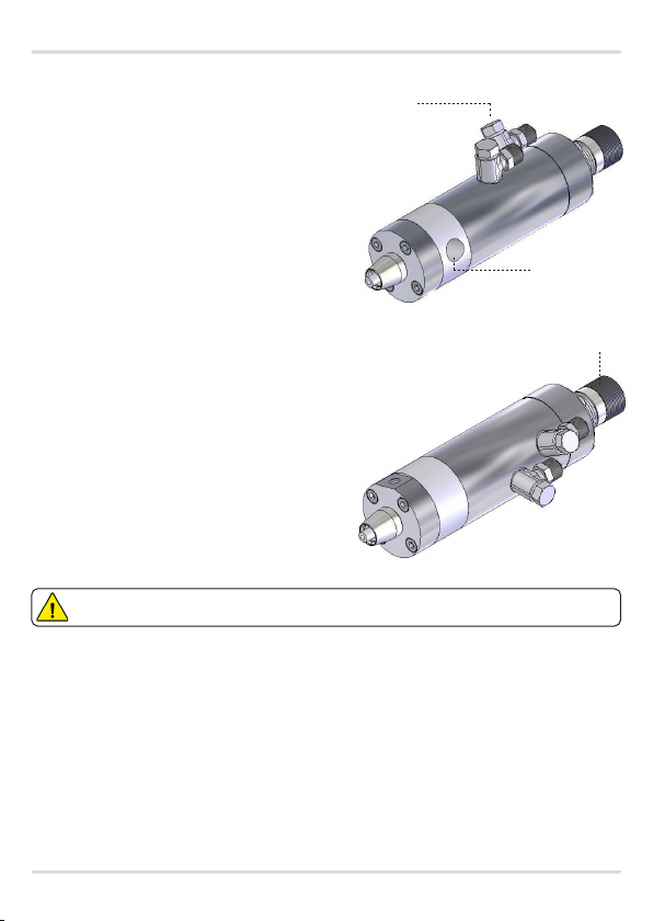
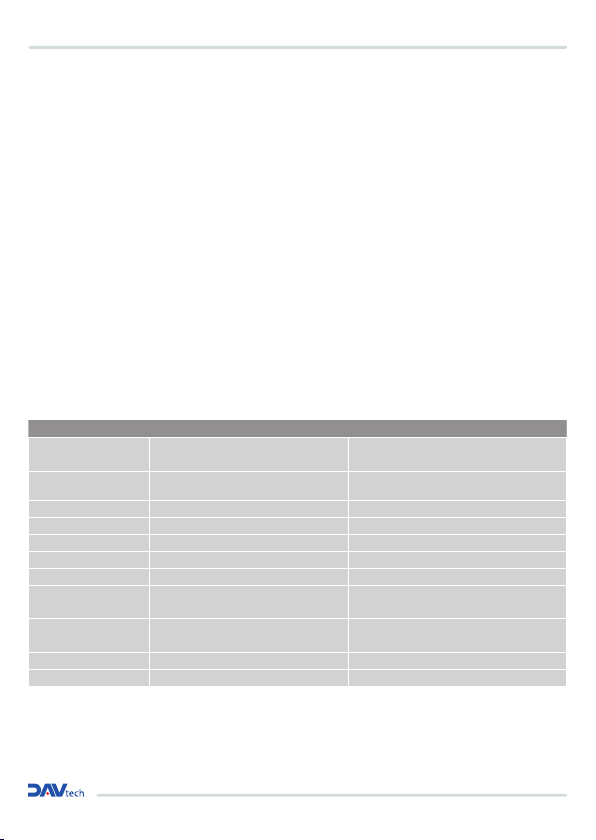
2 TECHNICAL DESCRIPTION
2.1 Valve Operation
DA250 dosing valve is designed and manufactured in compliance with current safety standards.
The DA250 should only be used for the application of anaerobic, cyanoacrylic or other aggressive fluids at a maximum
pressure of 10 bar. Only qualified personnel are authorized to install and use the DA250 dispensing valve. Read and understand
this manual before installing and using the valve. For the dosing valve DA250 only and exclusively the use fields listed in this
manual are provided. All data and parameters in this manual must be respected. You can only use DAV Tech’s additional or
auxiliary equipment. Any other use is not contemplated.
2.2 Technical Specification
Model DA 250
Drive Simple or Double Acting
Max fluid pressure 10 bar
Operating pressure 5-7 bar
Thread inlet 1/8 BSP
Thread outlet Luer Lock or others on request
Speed Up to 200 cycles / min
Adjustment Micrometric screw adjustment
Used materials Anodized aluminum, stainless steel, PTFE, membrane co-molded with non-reactive materials
Fluids used Cyanoacrylate glue, anaerobic fluids, low viscosity fluids in general (even aggressive)