manuals.online logo
Brands
  1. Home
  2. •
  3. Brands
  4. •
  5. Honeywell
  6. •
  7. Control Unit
  8. •
  9. Honeywell VR4920Z 1000 User manual

Honeywell VR4920Z 1000 User manual

INSTRUCTION SHEET
VR4920Z 1000 AND 45.900.449-
DUAL VALVE ASSEMBLY APPLICABLE FOR BUILT--ON PURPOSES
EN1R--9181 0104R1--NE
DESCRIPTON
The VR4920Z 1000 dual valve has been specially developed
to have kits fit--on.
When a kit with a V7335A electric modulating regulator
(Modureg) is fitted on the dual valve assembly the type gas
control is equal to a VR4920M.
When a kit with a V4336A electric high low regulator is fitted
on the dual valve assembly the gas control is equal to a
VR4920P.
APPLICATION
The VR4920M provides the following functions:
Servo pressure regulation
Outlet pressure is held at a constant value regardless of
fluctuations of inlet pressure.
Modulating control
Between minimum and maximum outlet pressure gas
supply to the appliance is dependent on the electrical
signal to modulating coil.
Mechanical limitation of outlet pressure
The minimum and maximum burner pressures are
mechanically adjusted to guarantee good burner
performance in case the modulating control should
become out of range.
The VR4920M is designed to work together with the W9335
modulating Modureg control, W4115 logic control, T7335A
thermistor temperature sensor and an advanced range of
micro computer based modulating controls.
The VR4920P provides the following functions:
Servo pressure regulation
Outlet pressure is held at a constant value regardless of
fluctuations of inlet pressure.
High--Low control
Within the ranges specified a high and a low outlet
pressure can be mechanically adjusted and electrically
selected.
High outlet pressure to appliance will be established by
switching control voltage to High--Low coil on.
By switching voltage off, outlet pressure will drop to low
pressure setting.
1 Place gasket
note: orientation !!!
2 Fix operator with the four
screws provided
4 Fit Modureg or High--Low
regulator with the indent
beside the locating plug and
fix with the two screws
provided.
3 Place seal
5 Make soudness testing
6 Adjust Modureg or
High--Low setting
Fig. 1.
Subject to change without notice. Printed in the Netherlands.
2
EN1R--9181 0104R1--NE
127
230
A B
CD
E
E
G
K
H
L
172
M
A-- I n l e t
B-- O u t l e t
C-- Inlet pressure tap
D-- Outlet pressure tap
E-- 6.3 mm terminals
G-- Mounting holes (M5) for connecting flanges
H-- Earth screw
K-- Pilot outlet connection
L-- Pilot flow adjustment screw
M-- Optional for inlet pressure tap 1/8”BSPT
Fig. 2. Dimensions VR4929M/VR4920P
3EN1R--9181 0104R1--NE
HOW TO CREATE THE DIFFERENT
FINAL O.S. NUMBERS
As mentioned in the description the VR4920Z1000 is special
developed to have kits fit on it.
There are 5 different kits to order, with these 5 kits and valve
VR4920Z1000 it is possible to create 5 final OS numbers.
Each kit contains an operator and a Modureg or High Low
and screws and gaskets.
To create VR4920M2011:
use valve VR4920Z1000 and kit 45900449--006.
To create VR4920M2029:
use valve VR4920Z1000 and kit 45900449--005.
To create VR4920M2037:
use valve VR4920Z1000 and kit 45900449--003.
To create VR4920M2045:
use valve VR4920Z1000 and kit 45900449--004.
To create VR4920P2000:
use valve VR4920Z1000 and kit 45900449--002.
For the contents of a kit look at the label on the box.
HOW TO ASSEMBLE A COMPLETE
O.S. NUMBER
For assembling a VR4920M or VR4920P use fig. 1. as
guideline.
WARNING
Before assembling see if the correct kit is taken.
Take care that the gasket is placed in the correct
position.
After assembling and installation the valve perform the
gas leak test.
Perform gas leak test
WARNING
FIRE OR EXPLOSION HAZARD CAN CAUSE
PROPERTY DAMAGE, SEVERE INJURY OR
DEADTH
Check for gas leaks with an approved leak detection
fluid any time work is done on a gas control.
Gas leak test
Paint all pipe connections upstream of the gas control with
with an approved leak detection fluid.
Bubbles indicate a gas leak.
If a gas leak is detected, tighten the pipe connection.
Stand clear while lighting the main burner to prevent injury
caused from hidden gas leaks, which could cause flasback
in the appliance vestibule. Light the main burner.
With the main burner in operation, paint all pipe joints
(including adapters) and gas control inlet and outlet with an
approved leak detection fluid.
If another gas leak is detected, tighten adapter screws,
joints and pipe connections.
Replace the part if gas leak can not be stopped.
CAUTION
Keep leak detection fluid away from electrical
connections.
SPECIFICATIONS VR4920M
Model
VR4920M: line voltage gas control, fast opening with electric
modulating regulator V7335A
Ambient temperature
0 ... 70 _C
Minimum operating pressure
Between inlet and outlet: 3 mbar
Maximum operating pressure
The Pmax. indication on the housing of the gas control is the
maximum pressure at which the gas control functions safely.
However the maximum operating pressure is limited by the
pressure range of the Modureg concerned.
30 mbar for pressure range 1.5 ... 20 mbar
45 mbar for pressure range 3 ... 37 mbar
Adjustment points and dimensions
See fig. 3. page 4
Regulator output pressure range
See table 1. page 4
Electrical data gas control
Nominal voltage Current (mA) Power (W)
15 Vdc
240/240 Vac, 50 Hz
313
20.4/24
4.7
3.4/4.5
Electrical data V7335
Coil Direct current
(
m
A
)
Resistance at
2
0
_
__
_
C
(
τ
ττ
τ
Φ
ΦΦ
Φ
Voltage
(Vdc)
Color
(
mA) 20 _
__
_C
(
τ
ττ
τΦ
ΦΦ
Φ
15 white 50 ... 250 47.7 ... 52.3
28 green 30 ... 165 120 ... 130
WARNING
Do not exceed the maximum current value.
Electrical connection
The electric servo on/off operators are provided with: 6.3 mm
quick connect terminals suitable for 6.3 mm receptacles. (e.g.
”Series 250” AMP fasteners)
The Modureg is provided with quick connect terminals which
are suitable for 6.3 mm (1/4”) receptacles (e.g.series “250”
fasteners).
Enclosure (including cover)
IP 40
Modulation characteristics
Values are based on increasing current with start at zero.
When current is decreasing from its maximum value the outlet
pressure will be higher.
NOTE: Good and reliable performance of the Modureg is not
only dependent on the Modureg itself, but also upon
the reliability of the modulating control and sensor
used.
4
EN1R--9181 0104R1--NE
Table 1. Regulator outlet pressure range V7335A
Pressure range
(
m
b
a
r
)
Color of cap Setting
(
mbar) Minimum outlet pressure range
(mbar)
Maximum outlet pressure range
(mbar)
Sidewards Upwards
1.5 ... 20 grey 1.5 ... 15 2 ... 15 (min setting + 3) ... 20
3 ... 37 yellow 3 ... 25 4 ... 25 (min setting + 5) ... 37
INSTALLATION VR4920M
IMPORTANT
Take care that installer is a trained experienced
service person.
Turn off gas supply before starting installation.
Disconnect power supply to prevent electrical shock
and/or equipment damage.
Do not remove seals over inlet and outlet until the
device is ready to be installed.
Main gas connection
Take care that dirt cannot enter the gas control during
handling.
Ensure the gas flows in the same direction as the arrow on
the side of the combination gas control.
Pilot gas connection
Use a wrench to tighten fitting.
Do not use jointing compound.
Connect other end of tubing to pilot burner according to the
manufacturer’s instructions.
ADJUSTMENT, CHECKOUT AND
MAINTENANCE VR4920M
IMPORTANT
Adjustments should be made by qualified persons
only.
If the appliance manufacturer supplies checkout
and/or service and maintenance instructions,
carefully follow them. If such instructions are not
provided, then follow the procedure as outlined
below.
Allow time for pressure to stabilize before making
adjustments.
It is recommended that the Modureg is operated a
few times to ensure correct setting.
Remove cap before adjustment.
Take care that after any adjustment the cap is
mounted.
WARNING
The minimum pressure setting must first be adjusted
to ensure that burner will safely light up, then
maximum pressure setting can be adjusted.
Any adjustment of minimum pressure setting
influences maximum pressure setting.
76
38
Cap
Shaft
Adjustment screw (7 mm) for
maximum pressure setting
Adjustment screw (9 mm) for
minimum pressure setting
E”O”--ring
6.3 mm AMP
terminals
Fig. 3.
Pressure taps
The gas control is provided with a pressure tap of 9 mm outer
diameter at inlet and outlet side.
When checking the pressure undo the screw a half turn and
slip the tubing over the nipple.
Ensure that screw is retightened after making the test.
Pilot flame adjustment
The gas control is packed for shipment with pilot flow at
maximum. Refer to the pilot burner or appliance
manufacturer’s instructions for recommended size of pilot
flame.
If adjustment is required turn pilot adjustment screw clockwise
to decrease or counter--clockwise to increase pilot flame.
5EN1R--9181 0104R1--NE
Adjusting minimum pressure setting (see fig. 3.)
Connect a suitable pressure gauge to pipe line or to outlet
pressure tap of gas control concerned, to measure burner
pressure (measuring point must be as near to burner as
possible).
Disconnect electrical connection of Modureg.
Energize operator, set control in operation and wait until an
outlet pressure is recorded on pressure gauge.
If minimum rate pressure needs adjustment then use
a 9 mm wrench to turn adjustment screw for minimum
pressure setting clockwise to increase or
counter--clockwise to decrease pressure, until the desired
minimum outlet pressure is obtained.
Check if main burner lights easily and reliable at minimum
pressure.
Check maximum pressure setting and readjust if
necessary.
Mount cap.
Adjusting maximum pressure setting (see fig. 3.)
Connect a suitable pressure gauge to pipe line or to outlet
pressure tap of gas control concerned, to measure burner
pressure (measuring point must be as near to burner as
possible).
Disconnect electrical connection of Modureg.
Energize operator, set control in operation and wait until an
outlet pressure is recorded on pressure gauge.
Push shaft gently downwards to the maximum adjustment
screw and hold it on.
If maximum rate pressure needs adjustment then use
a 7 mm wrench to turn adjustment screw for maximum
pressure setting clockwise to increase or
counter--clockwise to decrease pressure, until the desired
maximum outlet pressure is obtained.
Release shaft.
Mount cap.
If minimum and maximum pressures are set, wire Modureg in
circuit.
Adjusting intermediate pressure setting
Some controls, such as W9335, are able to provide
modulating control as well as a fixed setting.
In case this intermediate pressure setting should be set, it is
necessary to follow the suppliers instructions regarding the
adjustment of the concerned control. It deals with the
switching from modulating mode to fixed setting mode which
is in most cases is a potentiometer.
The fixed setting mode is very often used for central heating,
where on/off adjustable pressure to burner is required.
This intermediate outlet pressure can in general be electrically
set as follows:
Connect a suitable pressure gauge to pipe line or to outlet
pressure tap of gas control concerned, to measure burner
pressure (measuring point must be as near to burner as
possible).
Energize operator, set control in operation and wait until an
outlet pressure is recorded on pressure gauge.
Make sure Modureg is wired in the circuit.
Bring system in fixed setting mode.
Adjust current as low as needed to obtain the lowest
pressure by using pressure setting means of control.
Mechanical setting of Modureg will prevent too low setting.
Increase the current until desired pressure is obtained by
using pressure setting means of modulating control.
Mount cap.
Checkout
After any adjustment, set appliance in operation and observe
through a complete cycle to ensure that burner system
components function correctly.
Maintenance
It is recommendable to check yearly the minimum and the
maximum setting and readjust them if necessary.
Dismounting and remounting flanges
Though by careful handling the “O”--rings could be re--used
when they are undamaged, it is advisable to use new
“O”--rings to be sure to have a reliable tight connection.
SPECIFICATIONS VR4920P
Model
VR4920P: line voltage gas control, fast opening with
High--Low regulator.
Ambient temperature
0 ... 70 _C
Minimum operating pressure
Between inlet and outlet: 3 mbar
Adjustment points and dimensions
See fig. 4. page 6
Maximum operating pressure
The Pmax. indication 30 mbar on the housing of the
combination gas control is the maximum pressure at which
the gas control functions safely. However the maximum
operating pressure is limited by the pressure range of the
High--Low pressure regulator concerned.
30 mbar for pressure range 3 ... 20 mbar
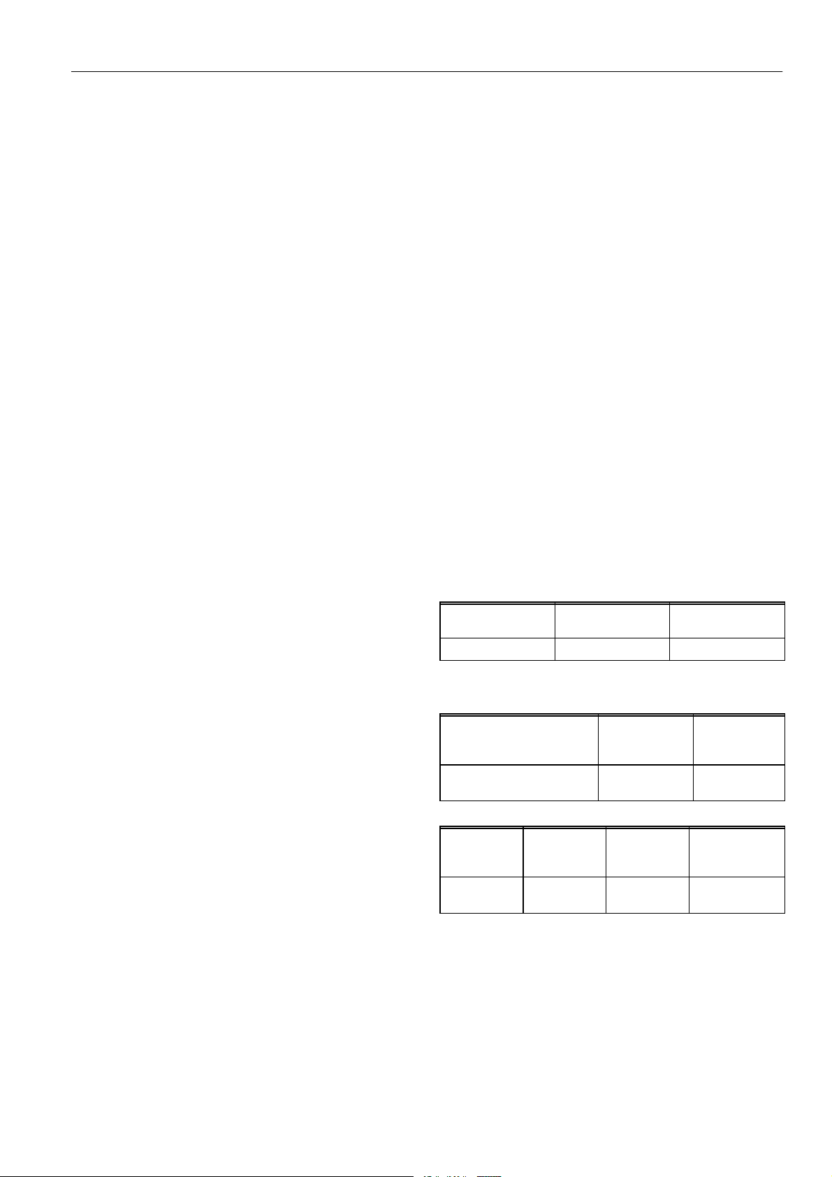
Regulator outlet pressure range V4336A
Pressure range
(mbar)
Low setting
(mbar)
High setting
(mbar)
3 ... 20 3 ... max. setting 7 ... 20
The outlet pressure setting should never be above the
range specified.
Electrical data gas control
Nominal voltage Current (mA) Power
consumption
(W)
15 Vdc
240/240 Vac, 50 Hz
313
20.4/24
4.7
3.4/4.5
Electrical data High- Low regulator V4336
Supply
voltage
(Vac)
Color of
coil
Current
(mA)
Power
consumption
(W)
220/240 V,
50 Hz
black 17.4/19 3/3.2
The High/Low regulator should never be covered in such
a way that temperature will raise beyond acceptable
limits.
Electrical connection
The electric servo on/off operators are provided with: 6.3 mm
quick connect terminals suitable for 6.3 mm receptacles. (e.g.
”Series 250” AMP fasteners)
6
EN1R--9181 0104R1--NE
The High--Low is provided with an earth terminal.
The High--Low is provided with quick connect terminals which
are suitable for 6.3 mm (1/4”) receptacles (e.g.series “250”
fasteners).
Also mPm type 122 connectors are to be used.
Ordernumber: 45.900.416--002..........................
NOTE: Good and reliable performance of the High--Low
regulator is not only dependent on the High--Low
itself, but also upon the reliability of the controller.
Enclosure (including cover)
IP 40
Electrical data
Supply
voltage
(Vac)
Color of
coil
Current
(mA)
Power
consumption
(W)
220/240 V,
50 Hz
black 17.4/19 3/3.2
The High/Low regulator should never be covered in such
a way that temperature will raise beyond acceptable
limits.
38
85
6.3 mm AMP
terminals
Cap
Adjustment screw for
maximum pressure setting
Adjustment screw for
minimum pressure setting
Earth terminal
Fig. 4.
ADJUSTMENT AND CHECKOUT
VR4920P
IMPORTANT
Adjustments should be made by qualified persons
only.
If the appliance manufacturer supplies checkout
and/or service and maintenance instructions,
carefully follow them. If such instructions are not
provided, then follow the procedure as outlined
below.
Allow time for pressure to stabilize before making
adjustments.
It is recommended that the High--Low regulator is
operated a few times to ensure correct setting.
It should be prevented, that High--Low regulator is
exposed to unneccessary forces because of wiring.
Cap has to be removed by putting a small screw
driver in one of the slots and lifting the cap carefully
while at the same time supporting the cap opposite
to the screw driver, (see fig. 5. page 7).
WARNING
Maximum pressure setting must first be adjusted then
minimum pressure setting can be adjusted.
Any adjustment of maximum pressure setting
influences minimum pressure setting.
Never adjust the maximum setting above the range
specified
Pressure taps
The gas control is provided with a pressure tap of 9 mm outer
diameter at inlet and outlet side.
When checking the pressure undo the screw a half turn and
slip the tubing over the nipple.
Ensure that screw is retightened after making the test.
Pilot flame adjustment (if applicable)
The gas control is packed for shipment with pilot flow at
maximum. Refer to the pilot burner or appliance
manufacturer’s instructions for recommended size of pilot
flame.
If adjustment is required turn pilot adjustment screw clockwise
to decrease or counter--clockwise to increase pilot flame.
Adjusting maximum pressure setting (see fig. 4. page 6)
Connect a suitable pressure gauge to pipe line or to outlet
pressure tap of gas control concerned, to measure burner
pressure (measuring point must be as near to burner as
possible).
Energize High--Low regulator, set gas control in operation
and wait until an outlet pressure is recorded on pressure
gauge.
Usea8mmwrenchtoturnadjustmentscrewformaximum
pressure setting clockwise to increase or
counter--clockwise to decrease pressure, until desired
maximum burner pressure is obtained.
Check maximum pressure setting after several times.
7EN1R--9181 0104R1--NE
Adjusting minimum pressure setting (see fig. 4. page 6)
Connect a suitable pressure gauge to pipe line or to outlet
pressure tap of gas control concerned, to measure burner
pressure (measuring point must be as near to burner as
possible).
Disconnect electrical connection of High--Low regulator.
Set gas control in operation and wait until an outlet
pressure is recorded on the pressure gauge.
When minimum pressure setting needs adjustment, then
use a 3.5 mm screw driver to turn adjustment screw for
minimum pressure setting clockwise to increase or
counter--clockwise to decrease pressure, until desired
minimum burner pressure is obtained.
Wire High--Low regulator coil in circuit.
Check maximum pressure setting and re--adjust if
necessary. Check minimum pressure setting again.
When High and Low pressure settings are correct, replace
cap
Checkout
Set appliance in operation after any adjustment and observe
several complete cycles to ensure that all burner components
function correctly.
Maintenance and service
Under normal circumstances no maintenance or service is
required.
Dismounting and remounting flanges
Though by careful handling the “O”--rings could be re--used
when they are undamaged, it is advisable to use new
“O”--rings to be sure to have a reliable tight connection.
Fig. 5.
8
EN1R--9181 0104R1--NE
Home and Building Control
Combustion Controls Center Europe
Honeywell BV
Phileas Foggstraat 7
7821 AJ Emmen
The Netherlands
Tel: +31 (--)591 695911
Fax: +31 (--)591 695200
http://europe.hbc.honeywell.com

Other Honeywell Control Unit manuals

Honeywell VR8200A User manual

Honeywell

Honeywell VR8200A User manual

Honeywell VRW2 User manual

Honeywell

Honeywell VRW2 User manual

Honeywell S8600A User manual

Honeywell

Honeywell S8600A User manual

Honeywell elBus 290097 User manual

Honeywell

Honeywell elBus 290097 User manual

Honeywell Gamewell FCI Velociti Series User manual

Honeywell

Honeywell Gamewell FCI Velociti Series User manual

Honeywell V4297A Series Operation manual

Honeywell

Honeywell V4297A Series Operation manual

Honeywell BSM Assembly instructions

Honeywell

Honeywell BSM Assembly instructions

Honeywell ADEMCO 4100SM Assembly instructions

Honeywell

Honeywell ADEMCO 4100SM Assembly instructions

Honeywell 9410 Series Instruction manual

Honeywell

Honeywell 9410 Series Instruction manual

Honeywell SDW 10 Service manual

Honeywell

Honeywell SDW 10 Service manual

Honeywell NOTIFIER 020-772 User manual

Honeywell

Honeywell NOTIFIER 020-772 User manual

Honeywell AM-1 Series User manual

Honeywell

Honeywell AM-1 Series User manual

Honeywell 5496 Operating instructions

Honeywell

Honeywell 5496 Operating instructions

Honeywell SG150 User manual

Honeywell

Honeywell SG150 User manual

Honeywell R7140G User manual

Honeywell

Honeywell R7140G User manual

Honeywell Krom Schroeder BCU 480 User manual

Honeywell

Honeywell Krom Schroeder BCU 480 User manual

Honeywell REDLINK ERM5220R Operation manual

Honeywell

Honeywell REDLINK ERM5220R Operation manual

Honeywell NOTIFIER SCS Series Specification sheet

Honeywell

Honeywell NOTIFIER SCS Series Specification sheet

Honeywell SUPER TRADELINE VR8300A User manual

Honeywell

Honeywell SUPER TRADELINE VR8300A User manual

Honeywell CA295 User manual

Honeywell

Honeywell CA295 User manual

Honeywell RV260 Series User manual

Honeywell

Honeywell RV260 Series User manual

Honeywell VP527A User manual

Honeywell

Honeywell VP527A User manual

Honeywell S4965 Series User manual

Honeywell

Honeywell S4965 Series User manual

Honeywell TR120 User manual

Honeywell

Honeywell TR120 User manual

Popular Control Unit manuals by other brands

System air SAVE CONNECT user manual

System air

System air SAVE CONNECT user manual

Control Technologies CTI 2557-A Installation and operation guide

Control Technologies

Control Technologies CTI 2557-A Installation and operation guide

Exor CDW10U2UL user manual

Exor

Exor CDW10U2UL user manual

B meters IWM-PL4 Quick user guide

B meters

B meters IWM-PL4 Quick user guide

Ublox EVA-M8E Hardware Integration Manual

Ublox

Ublox EVA-M8E Hardware Integration Manual

SimCom SIM800 Series Hardware design

SimCom

SimCom SIM800 Series Hardware design

Murrelektronik CUBE20S manual

Murrelektronik

Murrelektronik CUBE20S manual

Global Sat LD-11 Operation manual

Global Sat

Global Sat LD-11 Operation manual

System air TCA 150D2 operating instructions

System air

System air TCA 150D2 operating instructions

Cypress EZ-BLE PRoC manual

Cypress

Cypress EZ-BLE PRoC manual

COLORKINETICS CM-400 48V EO installation instructions

COLORKINETICS

COLORKINETICS CM-400 48V EO installation instructions

Ultra Max Perfoma Series Operation manual

Ultra Max

Ultra Max Perfoma Series Operation manual

Alarmcom Knowledge Base Verizon VoLTE installation guide

Alarmcom

Alarmcom Knowledge Base Verizon VoLTE installation guide

Ublox C101-D9C user guide

Ublox

Ublox C101-D9C user guide

Multitech SocketModem MTSMC-G3 Device guide

Multitech

Multitech SocketModem MTSMC-G3 Device guide

Keyautomation 14A Instructions and warnings for installation and use

Keyautomation

Keyautomation 14A Instructions and warnings for installation and use

HIK VISION DS-K2M062 user manual

HIK VISION

HIK VISION DS-K2M062 user manual

InWin 2RAKVI013101 user manual

InWin

InWin 2RAKVI013101 user manual

manuals.online logo
manuals.online logoBrands
  • About & Mission
  • Contact us
  • Privacy Policy
  • Terms and Conditions

Copyright 2025 Manuals.Online. All Rights Reserved.