manuals.online logo
Brands
  1. Home
  2. •
  3. Brands
  4. •
  5. eldoLED
  6. •
  7. DC Drive
  8. •
  9. eldoLED POWERdrive 562/S User manual

eldoLED POWERdrive 562/S User manual

Constant current LEDs are to be wired in
SERIES and require a MINIMUM and
maximum number of fixtures connected to
a driver as indicated on the following page.
POWERING or TESTING less than the MINIMUM number
of fixtures per driver OR connecting fixtures with
the driver live OR wiring them in parallel will
IMMEDIATELY and PERMANENTLY DESTROY the LEDs.
Carefully read instructions prior to installation and testing.
[email protected] inter-lux.com
STOP
Wire shall be 18 awg stranded minimum. Large gauge wire shall be used to limit voltage
drop in order to maintain the proper operating voltage. Take every precaution to avoid interferance from other
electrical circuits and equipment.
LEDs shall be wired in series as shown in wiring diagram. CAUTION: parallel wiring will damage LEDs.
Wiring Key Points
Dimming circuits are more sensitive to voltage drop and electrical interference from other
electrical sources.
Isolating LED wiring by dedicated circuit for each control zone is recommended.
1.
6.
5.
4.
3.
2.
LED’s can be permanently damaged if these points are not followed
Dimming
Project: Type:
Manufacturer: Fixture:
Date:
Page:
Driver Dimming
Minimum number
of xtures
Maximum number
of xtures
AC Input
Constant Current drivers
7.
prior to energizing the circuit.
All Class II power cable remote wiring and driver enclosures by others.8.
Group 1:
Group 2:
+
-
LED
+
LED -
+
LED -
+(red)
-(black)
+
-
LED
+
LED -
+
LED -
+(green)
-(black)
+
-
LED
+
LED -
+
LED -
+(blue)
-(black)
Hot (black)
Neutral (white)
AC input
ground
(green)
Group 1
Group 2
Group 3
Constant Current Driver
Fixtures wired in series.
Refer to information below for
Minimum and Maximum
powered fromthe same
Group(DC output)
Black 1
Red 1
Current
setting (mA)
Group 3:
Black 2
Green 2
Black 3
Blue3
For White only
fixtures: Divide
the maximum
number of fixtures
per driver equally
between the 3
outputs/groups
Please note: Dimming/control wiring not shown in the diagram above.
PW0562S1
120/277V
0-10V
1
0
0
LINEALIGHT
2 OF 6
Wire Gauge Maximum Lead Length
18 72 ft (22 m)
16 118 ft (36 m)
14 150 ft (46 m)
12 200 ft (61 m)
*Actual distance must be calculated by installer.
Must comply with NEC code.
Dry Location Enclosure
Maximum Wiring Distance Guide*
13.25"(L) x 5” (W) x 2.25” (H)
surface mount in any orientation
© 2014 eldoLED. All rights reserved. V1.1
More documentation and eldoLED’s terms and conditions are available at www.eldoled.com.
Pay attention when connecting the LED groups:
polarity reversal results in no light output and often damages the LEDs
DMX in +
DMX in
-
DMX in
shield
120-277 VAC
2
1
9 mm
0.35 inch
0.5-1.5 mm2
AWG 20-16
L
N
3 LED groups
3 control channels
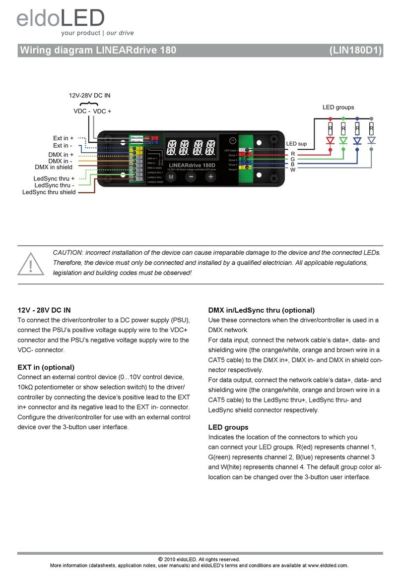
Wiring diagram POWERdrive 562/S, 562/A (PW0562S1, PW0562A1)
WARNING: Risk of electrical shock. May result in serious injury or death. Disconnect power before servicing or installing.
CAUTION: The device may only be connected and installed by a qualified electrician. All applicable regulations, legislation and build-
ing codes must be observed. Incorrect installation of the device can cause irreparable damage to the device and the connected LEDs.
LED groups
Indicates the location of the connectors for your LED groups. R(ed)
represents channel 1, G(reen) represents channel 2 and B(lue) rep-
resents channel 3. The default group color allocation can be changed
using the TOOLbox pro and freely available FluxTool application.
Maximum wiring distance at full load (from LED driver to LED load):
LEDcode/NTC
The LEDcode/NTC interface allows connection of a 47kΩNTC therm-
istor for closed loop thermal control. The NTC throttle temperature is
programmable through the freely available FluxTool software (see
“Configuring your driver over DMX in”).
DMX in
Use these connectors when the driver is used in a DMX network.
Connect the network cable’s DMX+, DMX- and DMX shielding wire
(the orange/white, orange and brown wire in a CAT5 cable) to the
DMX in+, DMX in- and DMX in shield connector respectively.
Configuring your driver over DMX in
Download the FluxTool software from your eldoLED driver’s product
web page and connect a TOOLbox pro to DMX in to configure your
driver. You can configure:
• Various DMX parameters
• Dimming curve
• Minimum dimming level
• NTC throttle temperature
• LED drive current per output: from 200mA-1,050mA in 1mA steps
120-277 VAC
The driver has been designed for use with universal mains voltage in-
put of 120-277 VAC, 50/60Hz, or with DC input of 120-250V (emer-
gency lighting).
AWG value 20 19 18 17 16
Distance (m) 14 18 22 28 36
Distance (ft) 45.9 59 72.2 91.9 118.1
Please observe voltage drop over long cable lengths.
Longer cable lengths increase EMI susceptibility.
WARNING: Disconnect power before wiring the LED fixtures. Connecting the
fixtures to a live driver will immediately and permanently damage the LEDs
eldoLED B.V. Science Park Eindhoven 5125 5692 ED Son The Netherlands T +31 40 7820400 [email protected]
eldoLED America One Lithonia Way Conyers, GA30012 USA T +1 877 353 6533 [email protected]
Wiring diagram POWERdrive 562/S, 562/A (PW0562S1, PW0562A1)
Connecting 2 LED groups
Connecting 1 LED group

This manual suits for next models

3

Other eldoLED DC Drive manuals

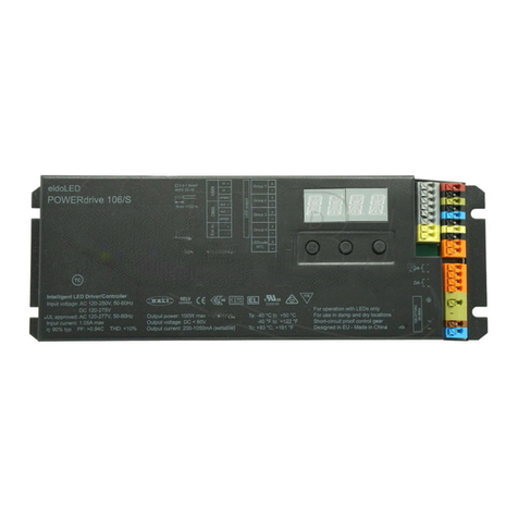
eldoLED POWERdrive 45D Quick start guide

eldoLED

eldoLED POWERdrive 45D Quick start guide

eldoLED POWERdrive 106/S Quick start guide

eldoLED

eldoLED POWERdrive 106/S Quick start guide

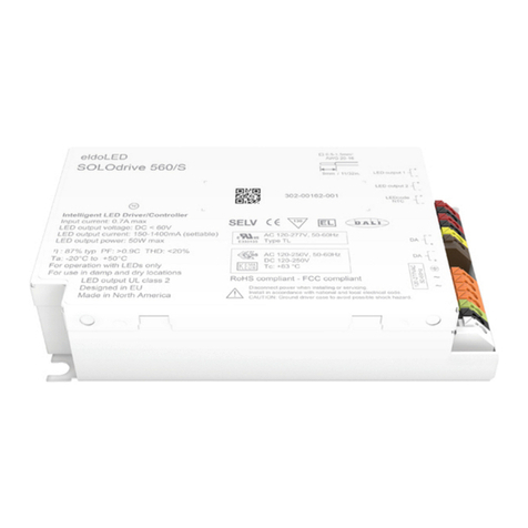
eldoLED SOLOdrive 560/S Quick start guide

eldoLED

eldoLED SOLOdrive 560/S Quick start guide

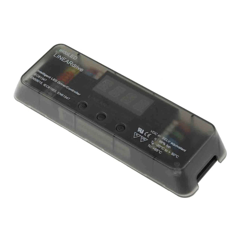
eldoLED LINEARdrive 720D User manual

eldoLED

eldoLED LINEARdrive 720D User manual

eldoLED POWERdrive 561/M Quick start guide

eldoLED

eldoLED POWERdrive 561/M Quick start guide

eldoLED LINEARdrive 180 Quick start guide

eldoLED

eldoLED LINEARdrive 180 Quick start guide

eldoLED LINEARdrive 720D Quick start guide

eldoLED

eldoLED LINEARdrive 720D Quick start guide

eldoLED LINEARdrive 720D User manual

eldoLED

eldoLED LINEARdrive 720D User manual

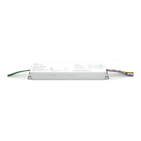
eldoLED ECOdrive Series User manual

eldoLED

eldoLED ECOdrive Series User manual

Popular DC Drive manuals by other brands

Overland Storage NEO 8000 Remove & Replace / Add-On Instructions

Overland Storage

Overland Storage NEO 8000 Remove & Replace / Add-On Instructions

elero RolTop S OPERATING AND INSTALLATION Manual

elero

elero RolTop S OPERATING AND INSTALLATION Manual

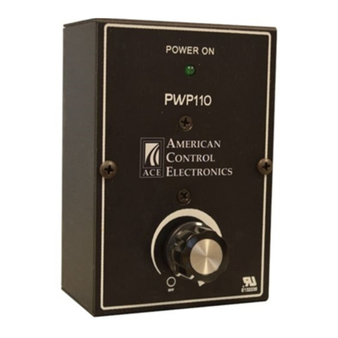
American Control Electronics PWP110 Series quick start guide

American Control Electronics

American Control Electronics PWP110 Series quick start guide

Rexnord Falk Quadrive A Series owner's manual

Rexnord

Rexnord Falk Quadrive A Series owner's manual

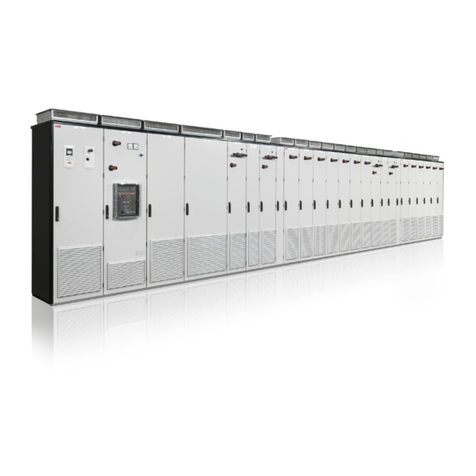
ABB ACS 6000 user manual

ABB

ABB ACS 6000 user manual

Masterflex L/S 772000-20 operating manual

Masterflex

Masterflex L/S 772000-20 operating manual

Binks QMS-430 Service bulletin

Binks

Binks QMS-430 Service bulletin

Vincent Associates UNIBLITZ ED12DSS user manual

Vincent Associates

Vincent Associates UNIBLITZ ED12DSS user manual

elero CSM-F-868 quick start guide

elero

elero CSM-F-868 quick start guide

Lenze AC Tech MCH Series Quick reference guide

Lenze AC Tech

Lenze AC Tech MCH Series Quick reference guide

YASKAWA JOHB-SMP3 Technical manual

YASKAWA

YASKAWA JOHB-SMP3 Technical manual

Lenze L-force EWS0069 Mounting instructions

Lenze

Lenze L-force EWS0069 Mounting instructions

ABB ACS880-207 Hardware manual

ABB

ABB ACS880-207 Hardware manual

GFA ELEKTROMAT SI installation instructions

GFA

GFA ELEKTROMAT SI installation instructions

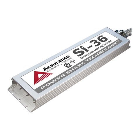
Assurance Engineering Emergency Lighting Si-36 instruction manual

Assurance Engineering

Assurance Engineering Emergency Lighting Si-36 instruction manual

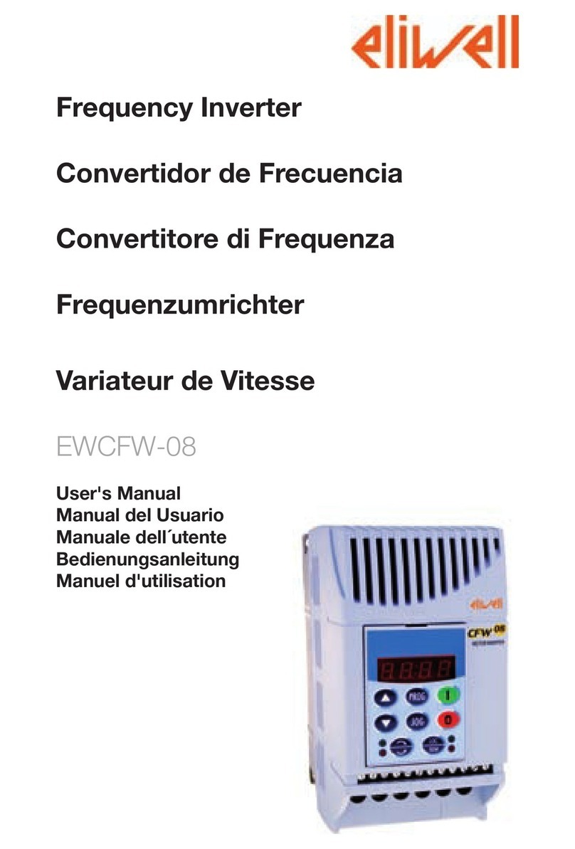
Eliwell EWCFW-08 user manual

Eliwell

Eliwell EWCFW-08 user manual

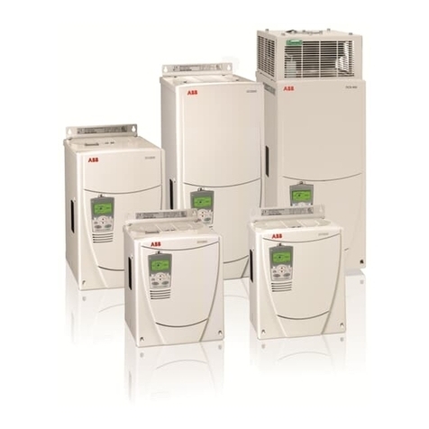
ABB DCS800 quick guide

ABB

ABB DCS800 quick guide

WOBIT SDC107 user manual

WOBIT

WOBIT SDC107 user manual

manuals.online logo
manuals.online logoBrands
  • About & Mission
  • Contact us
  • Privacy Policy
  • Terms and Conditions

Copyright 2025 Manuals.Online. All Rights Reserved.