5 Installation Procedure
10 YASKAWA SIEP C730600 0IA Modbus TCP/IP Technical Manual
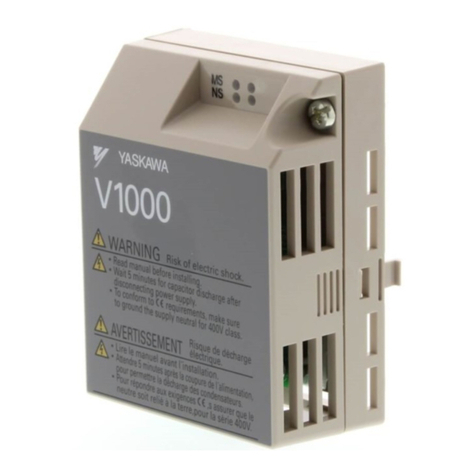
◆Option LED States
A - 1000-Series, Z1000U
B - GA500, GA700, GA800, CR700
C - Z1000, HV600 *1
Figure 4.2 Option LED Labels
*1 LED label has transparent background and white letters. Please make sure that you use the correct label for Z1000 or HV600.
Wait 2 seconds minimum for the power-up diagnostic process to complete before you verify the LED states. Table
4.2 shows the operating status of the option LEDs after the power-up diagnostic LED sequence is complete.
Table 4.2 Option LED States
LED Name
Indication
Operating State Description
Color State
MS
(Module Status)
- OFF Power supply off There is no power to the drive.
Green ON Option operating The option is operating normally.
Green Flashing Option initializing The option is configuring an IP address.
Red ON Fatal error occurred The option detected a fatal (unrecoverable) error.
Red Flashing Non-fatal error occurred The option detected a non-fatal (recoverable) error.
NS
(Network Status)
- OFF Power supply OFF or Offline -
Green ON Online communications established The option is online and has established connections.
Green Flashing Control connection active The option is online and has an established and active control
connection.
Red ON Communications error (fatal) The option detected a duplicate IP address.
10/100 *1
- OFF 10 Mbps is established
-
Green ON 100 Mbps is established
LINK/ACT *1
- OFF Link is not established
Green ON Link is established
Green Flashing Link is established and there is network
activity
*1 To verify LED states, you must remove the drive front cover. Do not touch the drive main circuit terminal or circuit boards when you
remove the drive front cover.
5 Installation Procedure
◆Section Safety
DANGER Electrical Shock Hazard. Do not examine, connect, or disconnect wiring on an energized drive. Before
servicing, disconnect all power to the equipment and wait for the time specified on the warning label at a minimum. The internal
capacitor stays charged after the drive is de-energized. The charge indicator LED extinguishes when the DC bus voltage
decreases below 50 Vdc. When all indicators are OFF, measure for dangerous voltages to make sure that the drive is safe. If
you do work on the drive when it is energized, it will cause serious injury or death from electrical shock.
WARNING Electrical Shock Hazard. Do not operate the drive when covers are missing. Replace covers and shields
before you operate the drive. Use the drive only as specified by the instructions. Some figures in this section include drives
without covers or safety shields to more clearly show the inside of the drive. If covers or safety shields are missing from the
drive, it can cause serious injury or death.
WARNING Electrical Shock Hazard. Only let approved personnel install, wire, maintain, examine, replace parts, and
repair the drive. If personnel are not approved, it can cause serious injury or death.
WARNING Electrical Shock Hazard. Do not remove covers or touch circuit boards while the drive is energized. If you
touch the internal components of an energized drive, it can cause serious injury or death.
WARNING Electrical Shock Hazard. Do not use damaged wires, put too much force on the wiring, or cause damage to
the wire insulation. Damaged wires can cause serious injury or death.

