eldoLED POWERdrive 6060/R User manual
© 2015 eldoLED. All rights reserved. V1.2 All content contained herein is subject to change without prior notice.
More product documentation and eldoLED´s terms and conditions are available at www.eldoLED.com
Design-in guide
POWERdrive 6060/R

2
Table of Contents
1. Technical characteristics 4
1.1 Input characteristics 4
1.2 Output characteristics 5
1.3 Control characteristics 5
1.4 Protection 5
1.5 Thermal characteristics 5
1.6 Thermal protection 6
1.7 Dimensions, weight and packaging 6
1.8 Standards compliance 6
1.9 Certifications 6
2. Wiring 7
2.1 Wiring specifications 7
2.1.1 General wiring specifications 7
2.1.2 Power cord requirements 7
2.1.3 Sample voltage drop calculation 8
2.2 Connections 8
2.2.1 DMX network options 9
2.2.2 LED outputs 11
2.2.3 LEDcode/NTC 12
2.2.4 0-10V 12
2.2.5 DALI 12
2.2.6 120-230V AC 12
3. Installing the POWERdrive 6060/R 13
3.1 Cable connections 13
3.2 Common practice for grounding LED wires 14
3.3 Cable trunk 15
4. Configuring POWERdrive 6060/R 16
4.1 Menu button combinations 16
4.2 Order of LED driver configuration 16
4.3 Setting the operation mode 17
4.4 Setting the LED output current and LED group configuration 17

3
Safety guidelines 20
Disclaimer 21
Warranty 22
4
1. Technical characteristics
1.1 Input characteristics
Input voltage AC
120-230V
Input current
6.3A max @ 120V / 60Hz
5A max @ 230V / 50Hz
Input frequency
50-60Hz
Power factor
>0.9 @ 25% load and higher
Total Harmonic Distortion
<20% between 2/3 load and full load
Efficiency @ full load
91.8%
Efficiency @ 2/3 load
91.2%
Inrush current
35A @ 115V AC
70A @ 230V AC
Surge protection
EN 61000-4-5 compliant
Standby power
12.5W @ 100V AC
12.8W @ 120V AC
14.4W @ 230V AC
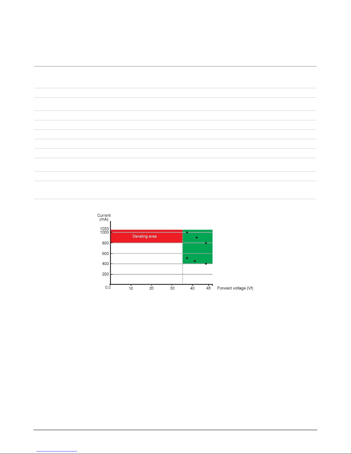
Figure 1.1 Derating diagram
To avoid temperature rise affecting lifetime, it is recommended not to use configurations in the derating area of the diagram above. The green area
indicates the highest efficiency area of POWERdrive 6060/R.
Calculation examples in the high efficiency area, using the formula (number of LED outputs) * ( Iout ) * ( VLED )
Using all 32 LED outputs:
32 LED outputs * 0.5A * 37.5V = 600W
32 LED outputs * 0.45A * 41.6V = 599W
32 LED outputs * 0.4A * 46.8V = 600W
Using 16 LED outputs:
16 LED outputs * 1A * 37.5V = 600W
16 LED outputs * 0.9A * 41.6V = 599W
16 LED outputs * 0.8A * 46.8V = 600W

5
1.2 Output characteristics
LED outputs
32
LED output power
600W max
LED output voltage range
2-48V
LED output current range
200-1,050mA
LED output current resolution
Programmable in 50mA steps
LED output current accuracy
+/- 10%
1.3 Control characteristics
Control channels
1-32 over DMX/RDM, 1-4 over DALI, 1 over 0-10V
Dimming protocol
USITT DMX512A // RDM, DALI or 0-10V
Dimming range
100%-0%
Dimming method
Hybrid HydraDrive
Dimming curve
Linear, logarithmic, square
Driver configuration
via front display and menu buttons
Isolation 0-10V to line voltage input
1500V
Isolation 0-10V to LED output
3750V
0-10V current draw
2mA
1.4 Protection
LED output short
Yes
LED output cross short
Yes
Overload
Yes
Reverse polarity
Yes, for LED output
Restart after protection
1.5 Thermal characteristics
Ta operating range
-20 °C … +50 °C / -4 °F … +122 °F
Tc max
85 °C / 185 °F
Tc lifetime
78 °C / 172 °F
6
1.6 Thermal protection
External NTC thermistor
Throttling @ 70 °C / 158 °F (settable)
External NTC thermistor value
47kOhm
Recommended NTC thermistor
238164063473 (leaded)
NTCASCWE3473J (screw)
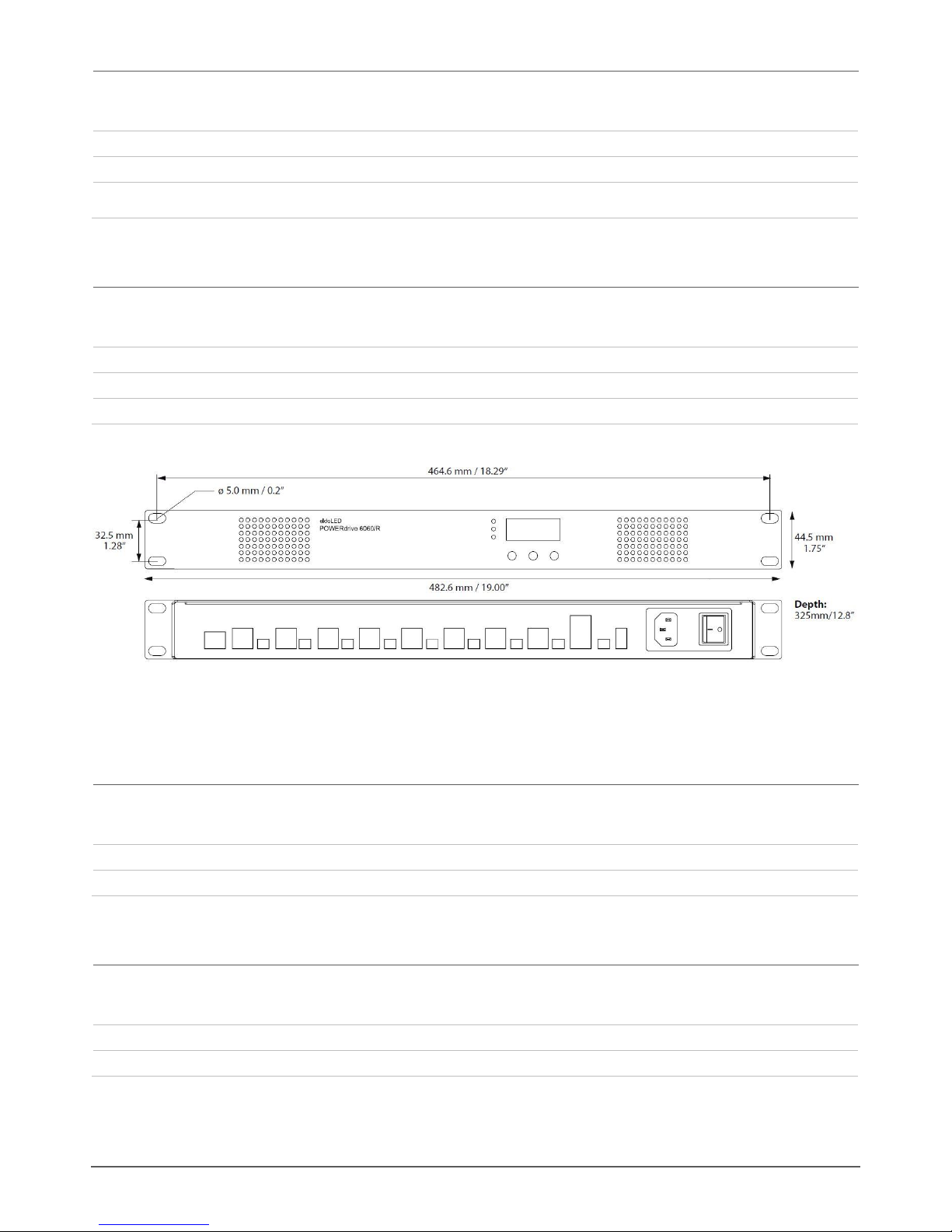
1.7 Dimensions, weight and packaging
L x W x H
482.6 x 325 x 44.5mm / 19 x 12.8 x 1.75in
Weight
6.3kg / 13 lb, 14.23 oz
Packaging
1 pc
Figure 1.2 POWERdrive 6060/R dimensions
1.8 Standards compliance
EN
EN 55022, EN 62386-101/102/207, EN 60929 Annex E
RoHS
RoHS2
1.9 Certifications
CE
Directives 2004/108/EC, 2006/95/EC, 2011/65/EU
UL
Pending

7
2. Wiring
2.1 Wiring specifications
2.1.1 General wiring specifications
Wire type
AWG20 –AWG16, 0.5-1.5mm2
Wire core type
Solid or stranded copper
Wire strip length
9mm, 0.35in
The maximum length of LED wiring is 100m / 328ft from LED output to LED load when using 16 AWG type wires.
Refer to the table below for the maximum LED wiring length for other wire types:
AWG value
20
19
18
17
16
Distance (m)
14
18
22
28
36
Distance (ft)
46
59
72
92
118
Please observe a voltage drop over long wire lengths: the longer the wire length between LED output and LED load, the lower the forward voltage is
that is available to you per LED output.
2.1.2 Power cord requirements
Europe excluding UK
certified according to EN50525 norm
CEE7 mains plug
IEC60320 C13 connector
H05VV F3 x 0.75mm2cable
United Kingdom
certified according to EN50525 norm
BS1363A mains plug
IEC60320 C13 connector
H05VV F3 x 1.0mm2cable
USA
UL listed
NEMA 5-15P mains plug
IEC60320 C13 connector
S 3x 18AWG/16AWG VCTF3x 0.75mm2cable
Type SP-2, Type SPE-2, Type SPT-2, or heavier cord, minimum 1.5 m
(5 ft) in length

8
2.1.3 Sample voltage drop calculation
Situation ‘X’:
Wire resistance (Rwire): 0.02Ohm/m (check the specifications of the wire you are using)
Distance from LED output to LED load (L): 100m
LED load used (If): 1.05A
Calculation of available forward voltage for situation X:
Vf max =
48V - (2 * Rwire * L * If)
48V - (2 * 0.02 * 100 * 1.05) = 43.8V
From the above follows that in situation X you have a voltage drop of 48V - 43.8V = 4.2V per LED output
EMI susceptibility will increase with longer wire lengths.
2.2 Connections
Figure 2.1 POWERdrive 6060/R connections
WARNING: risk of electrical shock. May result in serious injury or death. Disconnect power before servicing or installing.
CAUTION: the device may only be connected and installed by a qualified electrician. All applicable regulations, legislation and building
codes must be observed. Incorrect installation of the device can cause irreparable damage to the device and the connected LEDs.
CAUTION: pay attention when connecting the LEDs: polarity reversal results in no light output and often damages the LEDs.

9
2.2.1 DMX network options
Bussed DMX
To set up a bussed DMX network:
Use the ‘DMX in’ and ‘DMX thru’ connectors as shown in the diagram below
Set the correct DMX start address for each POWERdrive
Make sure you terminate the last POWERdrive 6060/R with a resistor that matches the impedance of the cable used as close to its ‘DMX
in’ connector as possible.
DMX+, DMX- and DMX Shield (the orange-white, orange and brown wire in a CAT5 cable) are pin 1, 2 and 7 of the RJ45 connector.
Figure 2.2 Bussed DMX

10
Daisy-chained DMX
To set up a daisy-chained DMX network:
Use the ‘DMX in’ and ‘DMX out’ connectors as shown in the diagram below
Set the correct DMX start address for the first POWERdrive in a group
Make sure you terminate the POWERdrives at their ‘DMX in’connector when the wire length between drivers is over 20m. Use a resistor
that matches the impedance of the cable that has been used.
DMX+, DMX- and DMX Shield (the orange-white, orange and brown wire in a CAT5 cable) are pin 1, 2 and 7 of the RJ45 connector.
Figure 2.3Daisy-chained (buffered) DMX

11
2.2.2 LED outputs
POWERdrive 6060/R features 32 LED outputs. Note that if you want to connect an LED load to every LED output, the maximum current per output
is 800mA. Refer to Chapter 1, Technical Characteristics, for more information on derating and LED wiring.
LED outputs controlled over DMX/RDM
When you are using the DMX or RDM protocol, you can assign a DMX address to every single LED output. For configuration options such as LED
output current, however, the LED outputs are grouped according to the corresponding current sources.
Figure 2.4 POWERdrive 6060/R LED outputs and corresponding current sources
LED outputs controlled over DALI
When you are using the DALI protocol, you can define up to 4 DALI ballasts for every POWERdrive 6060/R with your DALI commissioning tool.
Figure 2.5 Up to 4 DALI ballasts
LED outputs controlled over 0-10V
When you are controlling the POWERdrive 6060/R over 0-10V, all LED outputs are controlled over the same channel, i.e. all LED outputs will show
the same behavior.
Figure 2.6 One 0-10V control channel
12
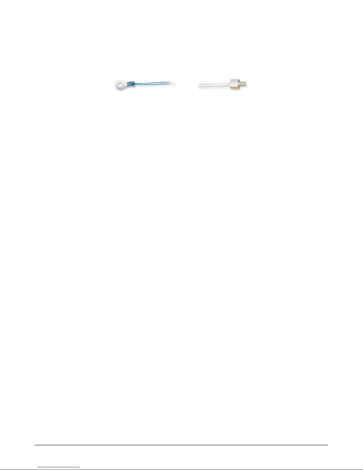
2.2.3 LEDcode/NTC
For extensive thermal management purposes, you can use an NTC thermistor. This sensor can be fastened on or near the LED engine, and its
wires connected to the LEDcode/NTC connectors.
Figure 2.7 Examples of NTC thermistors
The NTC thermistor feeds the temperature values that it detects to the driver. Whenever these values exceed the predefined NTC temperature limit,
the driver will gradually decrease the light output until normal operating temperatures are reached.
You can connect a 47kOhm NTC thermistor to the LEDcode/NTC interface for this closed loop thermal control. Recommended NTC thermistors
include:
238164063472 (leaded)
NTCASCWE3473J (screw)
2.2.4 0-10V
Connect your 0-10V control device to the ‘0-10V+’and ‘0-10V-’connector on the POWERdrive 6060/R.
2.2.5 DALI
Use the DALI connectors to connect the POWERdrive 6060/R to a DALI network. Always combine a DA+ and DA- connector for either data input or
data output. You can address the LED outputs over a total of 4 DALI ballasts.
2.2.6 120-230V AC
The LED driver has been designed for use with universal mains voltage input of 120-230V AC, 50-60Hz.
13
3. Installing the POWERdrive 6060/R
This chapter gives guidelines for the installation of POWERdrive 6060/R with regard to cable connections, grounding the LED output wires and use
of cable trunks.
3.1 Cable connections
It is recommended that you use shielded cabling for the LED output wires that connect the 19” rack unit to the LED loads in order to reduce EMI
(Electromagnetic Interference). This will enable the installing party to meet EMC requirements.
For connection of LED, NTC and LEDcode wires, use the mating connectors listed below:
2-pole terminal block, Phoenix contact FMC 1.5/2-ST-3.5-1952267 P1334
4-pole terminal block, Phoenix contact FMC 1.5/4-ST-3.5-1952283 P1348
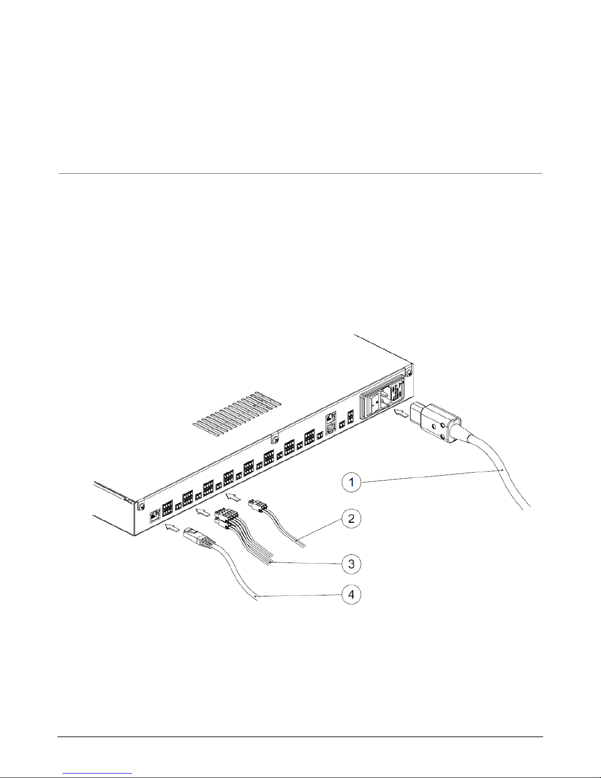
Figure 3.1 Cable connections: mains cable (1), NTC and LEDcode wires (2), LED wires (3) and DMX cable (4)

14
3.2 Common practice for grounding LED wires
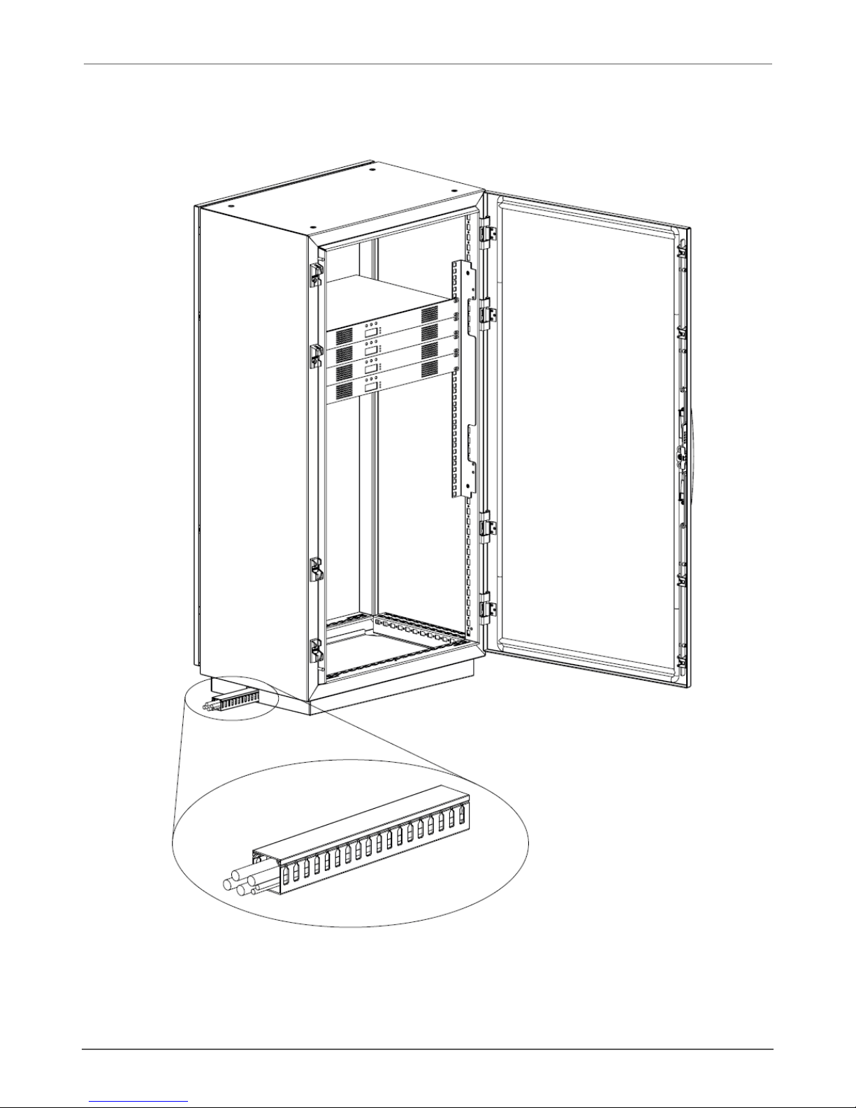
POWERdrive 6060/R has been designed for installation in a 19” rack. It is recommended to ground the shielded LED output cables both at the
19”rack unit and close to the LED load.
Inside the 19” rack unit, ground the LED wires as depicted in Figure 3.3 by leading them though an earthing clamp (2) that is attached to a C-rail (1).
Ground the LED wires a second time as close to the LED load as possible.
Figure 3.2 Grounding LED wires inside 19” rack unit
15
3.3 Cable trunk
Cable trunks as depicted in Figure 3.3 will facilitate leading the wires over longer distances inside the building.
Figure 3.3 Using cable trunks

16
4. Configuring POWERdrive 6060/R
Configure the POWERdrive 6060/R over its intuitive, 3-button user interface with display. The easy-to-navigate menu allows you to set parameters
such as number of LED groups, DMX or DALI settings for networked mode and show/colour/dim values for standalone operation. You can also lock
the driver’s configuration and perform a test run of the connected LED groups.
This chapter explains how to work with the user interface, and lists the various menu items and selectable values.
4.1 Menu button combinations
POWERdrive 6060/R features three menu buttons on its front side (M, - and +) with which you can navigate the configuration menu. The display
above the buttons shows the menu options and values that can be selected for every option.
Pressing the M button
shows the current mode or the next menu option; use the M button to browse menus and settings without making any changes.
saves a changed value.
turns off the display after the last menu option has been displayed.
Pressing the + (plus) or - (minus) button
changes a value. The changed value is only saved when M is pressed.
Have you accidentally changed a value but haven’t confirmed it yet by pressing M? By refraining from pressing the buttons for at least 8 seconds,
you will leave the menu (display is turned off) without changing the value.
If you are in a menu and want to change to another menu, refrain from pressing the buttons for at least 8 seconds (display is turned off), and
subsequently press the button combination for the menu you want to change to.
4.2 Order of LED driver configuration
The very first time the LED driver is powered on, the display will show the LED driver type (POWER RACK), for a couple of seconds. Next, the
display shows “SET MODE”. Set the mode of operation before you move on to the other menu items.
If the power is interrupted to a POWERdrive 6060/R that has already been configured, the display will only show the driver type when the power
comes back on, but will not go to the Set Mode menu, as the driver’s configuration has been saved to memory.
Basic configuration of the POWERdrive 6060/R includes the following steps:
1. Set the mode of operation (see 4.3 Setting the operation mode).
2. Set the LED output currents and LED group configuration (see 4.4 Setting the LED output current and LED group configuration).
3. Configure or view the operation mode you have chosen (see 4.5).
4. Optional:
You can do a test run of all connected LEDs by simultaneously pressing the M, - and + buttons
You can hard or soft lock the configuration by simultaneously pressing the M and + button and holding this combination down for 5
seconds
You can reset the driver’s configuration to the factory defaults by simultaneously pressing the M, - and + buttons and holding this
combination down for 5 seconds

17
4.3 Setting the operation mode
To enter the SET MODE menu:
1. The very first time the driver is powered on, the display will show the driver type/name for a couple of seconds and then automatically
enter the SET MODE menu.
To manually enter the SET MODE menu, press the M button for 5 seconds
The display shows “SET”- “MODE”, followed by the name of the currently active operation mode
2. Using the minus or plus button, go to the operation mode of your choice (COLR, SHOW, DMX, DALI or 10V).
3. Press M to save your choice. The display will turn off after you have pressed the M button.
Figure 4.1 Set mode menu
If you have confirmed COLR as the mode of operation, it is recommended to set the LED groups and the LED output current first,
before entering the COLR menu to set the color of your choice: if the LED current is not set correctly (e.g. too low), there might not
be any light output for you to verify the color.
4.4 Setting the LED output current and LED group configuration
In the setup menu, you can configure the LED output currents per current source, set the LED group configuration, and define the NTC
temperature.
Ensure that the LEDs you’re connecting to the driver can handle the LED output current! For instance, connecting 500mA LEDs to a
driver that has been configured for a 700mA output current will blow up the LEDs!
Figure 4.2 Configuring LED output current, LED group configuration, NTC temperature
18
To set LED output currents and LED group configurations:
1. Press M and the plus button simultaneously.
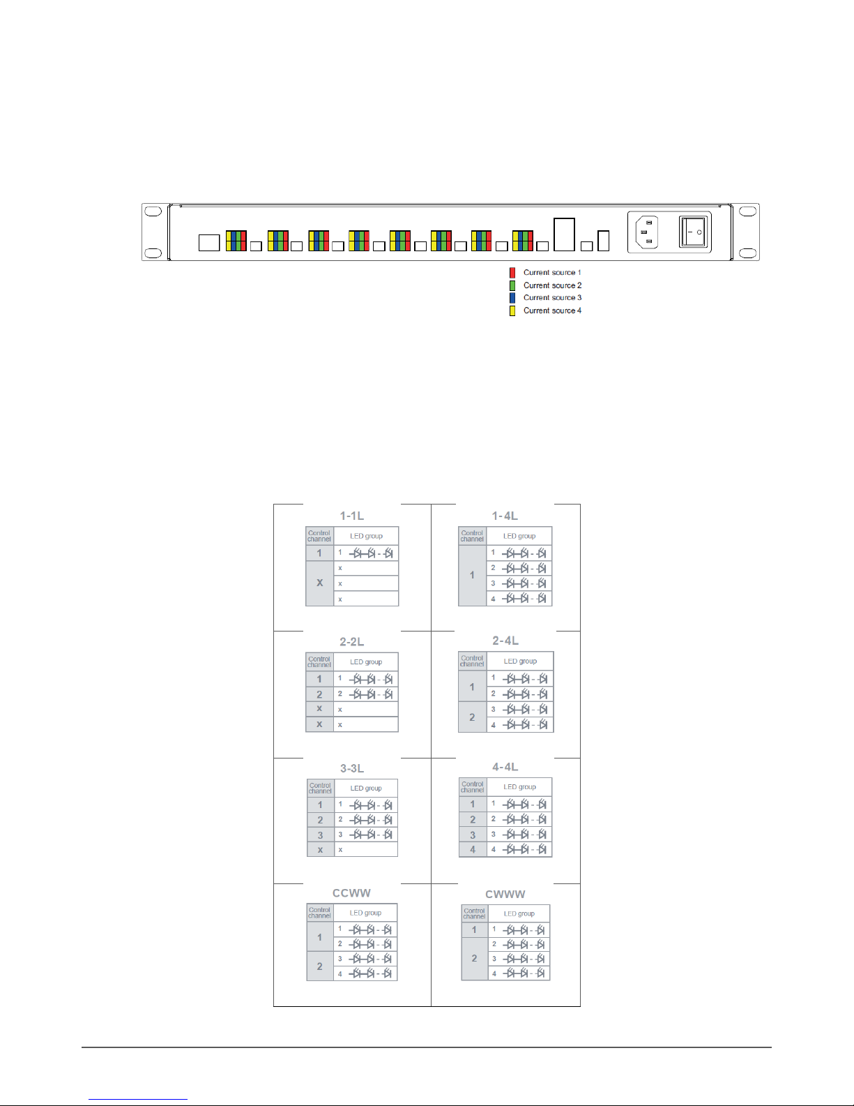
2. In the first menu (CUR1), select the LED output current for the current source 1. Figure 4.3 shows which current sources the LED outputs
are connected to. By pressing the plus or minus button you can go up or down in 50mA steps.
Figure 4.3 Current sources and corresponding LED outputs
3. Press M to save your choice, and repeat the same exercise for the LED outputs connected to current source 2 (CUR2), 3 (CUR3) and 4
(CUR4). Always save your selection by pressing M.
4. In the LED menu item, select the configuration of the LED groups that best fits your application. The below figures show the possibilities
offered in this menu item.
The LED group in pictures below refers to the Figure 4.3, which shows which current sources the LED outputs are connected to.

19
20
Safety guidelines
Before installing or performing routine maintenance upon this equipment, follow the general precautions listed in this Appendix. Installation should
be performed by a qualified licensed electrician. Maintenance should be performed by qualified person(s) familiar with the products’ construction
and operation and any hazards involved.
Do not install damaged product! This product has been properly packed so that no parts should have been damaged during transit. Inspect to
confirm.
WARNING: RISK OF ELECTRIC SHOCK:
- Disconnect or turn off power before installation
- Verify that supply voltage is correct by comparing it with the product information
- Make all electrical and grounded connections in accordance with all applicable local code requirements
- All wiring connections should be capped with UL approved recognized wire connectors
- All unused connector openings must be capped.
WARNING: RISK OF BURN OR FIRE:
- Do not exceed maximum wattage, ratings, or published operating conditions of product
- Do not overload
- Follow all manufacturer’s warnings, recommendations and restrictions to ensure proper operation of product
CAUTION: RISK OF DAMAGE DUE TO ESD (ELECTROSTATIC DISCHARGE):
- ESD can damage product(s). Personal grounding equipment must be worn during all installation of the unit.
- Do not touch individual electrical components as this can cause ESD and affect product performance.
CAUTION: RISK OF PRODUCT DAMAGE:
- Do not stretch or use cable sets that are too short or are of insufficient length.
- Do not tamper with contacts.
- Do not modify the product.
- Do not change or alter internal wiring or installation circuitry.
- Do not use product for anything other than its intended use.
Table of contents
Other eldoLED Lighting Equipment manuals


Popular Lighting Equipment manuals by other brands

GAME OF BRICKS
GAME OF BRICKS Thor's Hammer 76209 instruction manual

Rosco
Rosco DMX IRIS Operation manual

Ovation
Ovation C19 user manual

Melink
Melink ML1B5W20-GU15RGBCCT instruction manual

HUBBELL LIGHTING
HUBBELL LIGHTING DUAL LITE EVHC Series installation instructions

Gama Sonic
Gama Sonic 143iP2902KIT instruction manual


