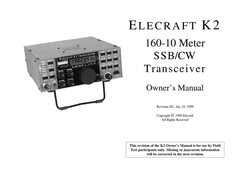
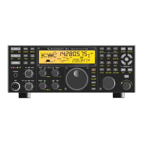
ELECRAFT K3 User manual

Elecraft •www.elecraft.com P.O. Box 69 •Aptos, CA 95001-0069 (831) 662-8345 •Fax: (831) 662-0830
ELECRAFT®K3
HIGH-PERFORMANCE 160 –6METER
TRANSCEIVER
K3 KIT ASSEMBLY MANUAL
PRELIMINARY
September 10, 2007
Copyright © 2007, Elecraft, Inc.
All Rights Reserved

ii
Contents
Introduction...............................................................................................................................................1
Customer Service and Support............................................................................................................................1
Technical Assistance.......................................................................................................................................1
Preventing Electrostatic Discharge Damage ............................................................................................3
How ESD Damage Occurs..................................................................................................................................3
Preventing ESD Damage..................................................................................................................................... 3
Preparing for Assembly............................................................................................................................4
Overview of the Kit.............................................................................................................................................4
Tools and Test Equipment Required...................................................................................................................6
Unpacking and Inventory....................................................................................................................................7
Screws.............................................................................................................................................................7
Standoffs .........................................................................................................................................................8
Lock Washers.................................................................................................................................................. 8
Assembly ..................................................................................................................................................9
RF Board and Chassis.........................................................................................................................................9
Circuit Description..........................................................................................................................................9
RF Board and Chassis Assembly Procedure................................................................................................. 11
KANT3 or KAT3 and Rear Panel.....................................................................................................................19
Circuit Description........................................................................................................................................19
KANT3 or KAT3 and Rear Panel Installation Procedure.............................................................................19
KIO3 Interface .................................................................................................................................................. 22
KIO3 Circuit Description..............................................................................................................................22
KIO3 Interface Installation Procedure .......................................................................................................... 23
Front Panel and DSP.........................................................................................................................................25
Circuit Description........................................................................................................................................25
Front Panel Assembly Procedure..................................................................................................................26
Resistance Checks......................................................................................................................................... 34
Initial Power On Check.................................................................................................................................35
KREF3 ..............................................................................................................................................................36
Circuit Description........................................................................................................................................36
KREF3 Installation Procedure ......................................................................................................................36
KSYN3..............................................................................................................................................................37
Circuit Description........................................................................................................................................37
KSYN3 Installation Procedure......................................................................................................................38
KPA3 Installation..............................................................................................................................................39
Bottom Cover....................................................................................................................................................39
Bottom Cover Installation.............................................................................................................................40
Battery BT1.......................................................................................................................................................41
Battery BT1 Function....................................................................................................................................41
Battery BT1 Installation Procedure............................................................................................................... 42
Top Cover and Speaker..................................................................................................................................... 42
Test and Calibration................................................................................................................................44
Initial Power Checks ......................................................................................................................................... 44
Synthesizer Calibration..................................................................................................................................... 45
Filter Setup........................................................................................................................................................45
Option Modules.................................................................................................................................................45
Transmitter Test................................................................................................................................................45
Wattmeter Calibration (Optional) ..................................................................................................................... 45
Reference Oscillator Frequency (Optional) ...................................................................................................... 45
KPA3 100-Watt Module Installation......................................................................................................46

iii
Appendix A, Illustrated Parts List ...................................................................................................... A1
Appendix B, K3 Functional Block Diagram.................................................................... .....................B1
List of Figures
Figure 1. Assembled Basic K3/10 (Less Top Cover).............................................................................................. 5
Figure 2. Screw Sizes Used in Assembly................................................................................................................7
Figure 3. Typical Standoff. ..................................................................................................................................... 8
Figure 4. Lock Washers. ......................................................................................................................................... 8
Figure 5. 2D Fastener Location on RF Board.......................................................................................................11
Figure 6. Installing 2D Fasteners on RF Board.....................................................................................................12
Figure 7. Noise Blanker Standoff Location. .........................................................................................................12
Figure 8. KNB3 Noise Blanker and KR MXR Mixer Standoff Hardware Installation. .......................................12
Figure 9. KR MXR Mixer Standoff Location.......................................................................................................12
Figure 10. Installing Q3 Hardware on RF Board..................................................................................................13
Figure 11. Installing Crystal I.F. Filters on RF Board. ......................................................................................... 13
Figure 12. RF Board Partially Assembled. ...........................................................................................................14
Figure 13. Installing the Low Power Amplifier (LPA)......................................................................................... 15
Figure 14. Installing Front Panel Shield................................................................................................................16
Figure 15. Installing KR MXR Mixer and KNB3 Noise Blanker Boards.............................................................16
Figure 16. Installing Side Panel Feet. ...................................................................................................................17
Figure 17. Installing Side Handle Mounting Hardware........................................................................................17
Figure 18. Mounting Left Side Panel.................................................................................................................... 18
Figure 19. Installing Left Side Panel 2D Fastener. ............................................................................................... 18
Figure 20. Attaching U12 and U13 to the Right Side Panel. ................................................................................19
Figure 21. Mounting the ANT1 Connector...........................................................................................................19
Figure 22. Mounting 2D fastener for KANT3 Standoff........................................................................................20
Figure 23. KANT3 Mounting Standoff................................................................................................................. 20
Figure 24. Installing the KANT3 or KAT3 Board................................................................................................ 20
Figure 25. Installing the Rear Panel......................................................................................................................21
Figure 26. ANT Connections to KANT3 or KAT3 Boards..................................................................................21
Figure 27. Installing Rear Panel Hole Plugs......................................................................................................... 22
Figure 28. Attaching Serial Number.....................................................................................................................22
Figure 29. Installing Rear Panel Ground Screw....................................................................................................22
Figure 30. Preparing Rear Panel for KIO3 Installation.........................................................................................23
Figure 31. Preparing the KIO3 Board for Installation...........................................................................................24
Figure 32. Installing KIO3 Main Board................................................................................................................24
Figure 33. Installing the KIO3 Digital I/O Board................................................................................................. 25
Figure 34. Mounting KIO3 Connector Panel........................................................................................................25
Figure 35. Preparing the Front Panel Board for Mounting, Part 1........................................................................27
Figure 36. Preparing the Front Panel Board for Mounting, Part 2........................................................................27
Figure 37. Mounting the Front Panel on the Front Panel Board...........................................................................28
Figure 38. Preparing VFO Encoders for Mounting...............................................................................................28
Figure 39. Mounting VFO Encoders.....................................................................................................................29
Figure 40. Mounting VFO A Trim Panel..............................................................................................................29
Figure 41. Installing LCD Cover...........................................................................................................................30
Figure 42. Mounting Concentric Knobs................................................................................................................ 30
Figure 43. Mounting Friction Knobs.....................................................................................................................31
Figure 44. Mounting the VFO A Tuning Knob. ...................................................................................................31
Figure 45. Mounting the VFO B Knob................................................................................................................. 32

iv
Figure 46. Mounting the DSP Board.....................................................................................................................33
Figure 47. Mounting the Front Panel Assembly on the Chassis. .......................................................................... 34
Figure 48. R36 Test Point. .................................................................................................................................... 35
Figure 49. U12 and U13 Test Points..................................................................................................................... 35
Figure 50. Installing KREF3 Board. .....................................................................................................................36
Figure 51. Installing KREF3 Oscillator Module................................................................................................... 37
Figure 52. Installing the KSYN3 Board................................................................................................................ 38
Figure 53. TMP Cable Connectors........................................................................................................................ 38
Figure 54. Installing KREF3 TMP Cables............................................................................................................ 39
Figure 55. Installing Standoffs on RF Board. .......................................................................................................40
Figure 56. Installing Rear Feet..............................................................................................................................40
Figure 57. Installing Tilt Stand. ............................................................................................................................ 41
Figure 58. Installing BT1......................................................................................................................................42
Figure 59. Attaching Chassis Stiffener to Top Cover...........................................................................................42
Figure 60. Mounting Loudspeaker........................................................................................................................43
Figure 61. Installing Speaker Magnet Shield........................................................................................................ 43
Figure 62. Connecting Speaker to KIO3 Board....................................................................................................44

1
Introduction
This is the assembly manual for the Elecraft K3 High Performance 160 – 6 meter transceiver modular kit.
Full details of the Elecraft K3 and its options, including specifications, installation, operation, troubleshooting
and maintenance instructions are included in the Owner’s Manual which accompanies this kit.
Even though the K3 is an advanced, multimode transceiver, you’ll be surprised at how easy this no-solder,
modular kit is to assemble. Only a few basic hand tools are needed (see page 6). Only a few pre-fabricated
cables are used in the K3. Nearly all interconnections are made through connectors mounted on the circuit
boards themselves.
Customer Service and Support
Technical Assistance
You can send e-mail to [email protected] and we will respond quickly - typically the same day Monday
through Friday. Telephone assistance is available from 9 A.M. to 5 P.M. Pacific time (weekdays only) at 831-
662-8345. Please use e-mail rather than calling when possible since this gives us a written record of the details
of your problem and allows us to handle a larger number of requests each day.
Repair / Alignment Service (We want to make sure everyone succeeds!)
If necessary, you may return your Elecraft product to us for repair or alignment. (Note: We offer unlimited email
and phone support to get your kit running, so please try that route first as we can usually help you find the
problem quickly.)
IMPORTANT: You must contact Elecraft before mailing your product to obtain authorization for the
return, what address to ship it to and current information on repair fees and turn around times. (Frequently we
can determine the cause of your problem and save you the trouble of shipping it back to us.) Our repair location
is different from our factory location in Aptos. We will give you the address to ship your kit to at the time of
repair authorization. Packages shipped to Aptos without authorization will incur an additional shipping charge
for reshipment from Aptos to our repair depot.

2
Elecraft 1-Year Limited Warranty
This warranty is effective as of the date of first consumer purchase. It covers both our kits and
fully assembled products. For kits, before requesting warranty service, you should fully complete
the assembly, carefully following all instructions in the manual.
What is covered: During the first year after date of purchase (or if shipped from factory, date
product is shipped to customer), Elecraft will replace defective or missing parts free of charge
(post-paid). We will also correct any malfunction to kits or assembled units caused by defective
parts and materials. Purchaser pays inbound shipping to us for warranty repair, we pay shipping to
return the repaired equipment to you by UPS ground service or equivalent to the continental USA
and Canada. Alaska, Hawaii and outside U.S. and Canada actual return shipping cost paid by
owner.
What is not covered: This warranty does not cover correction of kit assembly errors. It also does
not cover misalignment; repair of damage caused by misuse, negligence, or builder modifications;
or any performance malfunctions involving non-Elecraft accessory equipment. The use of acid-
core solder, water-soluble flux solder, or any corrosive or conductive flux or solvent will void this
warranty in its entirety. Also not covered is reimbursement for loss of use, inconvenience,
customer assembly or alignment time, or cost of unauthorized service.
Limitation of incidental or consequential damages: This warranty does not extend to non-
Elecraft equipment or components used in conjunction with our products. Any such repair or
replacement is the responsibility of the customer. Elecraft will not be liable for any special,
indirect, incidental or consequential damages, including but not limited to any loss of business or
profits.

3
Preventing Electrostatic Discharge Damage
There is no climate or work location where the components of your K3 are safe from Electrostatic Discharge
(ESD) unless you take specific steps to prevent such damage. Many of the components in your K3 can be
damaged by static discharges of only a few volts: far too little for you to notice. It is those low-voltage but
destructive discharges that easily happen anywhere and under virtually any environmental conditions.
ESD damage may not be apparent at first. The damaged components may not fail completely. Instead, the
damage may result in below-normal performance for an extended period of time before you experience a total
failure.
How ESD Damage Occurs
Whenever an object containing a static charge touches a circuit in your K3, current will rush into the circuit until
the components reach the same voltage as the source of the static charge. If the voltage or current that passes
through a component in your K3 during that brief period exceeds its normal operating specifications, it may be
damaged or destroyed.
Preventing ESD Damage
ESD damage cannot occur if there is no voltage difference between the components in your K3 and any object
that touches them. That is how anti-static packaging works. Anti-static bags allow the static charge to flow over
their surface, so that any part of the bag that touches the components inside are all at the same potential at all
times. Anti-static foam keeps the leads of sensitive components at the same potential.
At your work bench, avoiding a dangerous voltage is achieved most easily by tying everything together and
connecting them to a common mains safety ground. This includes your K3, individual boards or other sensitive
components as well as everything they may touch at the work table.
Inexpensive static dissipating work mats are readily-available that will steadily and safely drain off any charges
built up on parts or circuit boards placed on them. They are supplied with a lead that connects the mat to the
common workbench ground. Also, metal cabinets on test equipment used on the bench should be tied together
and connected to the common ground.
Most importantly, you must have a way of continuously draining off any static charges that occur on your body.
Such charges are easy to create, even while sitting quietly at the work bench. Moving your feet on the floor,
shifting position in your chair or even moving your arms so that clothing rubs against itself can all produce
destructive static charges. You can discharge yourself by touching an unpainted metal ground, but that will last
only until you move in a way that produces a new static charge. The safest technique is to wear a grounded wrist
strap with a series 1-megohm resistor that continuously drains off any charges. Such wrist straps are readily-
available and inexpensive.
WARNING
DO NOT attach a ground directly to yourself without a current-limiting resistor as this poses
a serious shock hazard. A wrist strap must include a 1-megohm resistor to limit the current
flow. If you choose to touch an unpainted, metal ground to discharge yourself, do it only
when you are not touching any live circuits with your other hand or any part of your body.
We strongly recommend you take the following anti-static precautions (listed in order of importance) to avoid
trouble:
•Leave ESD-sensitive parts in their anti-static packaging until you install them. The packaging may be a
special plastic bag or the component’s leads may be inserted in conductive foam. Parts which are

4
especially ESD-sensitive are identified in the parts list and in the assembly procedures.
•Wear a conductive wrist strap with a series 1-megohm resistor. If you do not have a wrist strap, touch a
ground briefly before touching any sensitive parts to discharge your body. Do this frequently while you
are working. You can collect a destructive static charge on your body just sitting at the work bench. DO
NOT attach a ground directly to yourself as this poses a serious shock hazard.
•Use a grounded anti-static mat on your work bench.
•If you choose to use a soldering iron to work on your K3 for any reason, be sure the iron is ESD-safe
with a grounded tip tied to the same common ground used by your mat or wrist strap.
Preparing for Assembly
Overview of the Kit
The kit comprises two major assemblies: the main chassis and the front panel. Figure 1 shows an assembled
K3/10 with its top cover removed.
The main chassis is literally built up around the RF circuit board, which fills the entire bottom of the unit of the
chassis assembly. Panels are mounted around the RF board using Elecraft’s 2D fasteners. These fasteners allow
individual removal of any one panel, if needed, to gain access to the inside of the radio for servicing. Very few
cables or wires are used in the kit. Most of the other boards and optional accessories plug directly into the RF
board or one of the boards mounted on the RF board.
The front panel assembly, including the display and main operator controls, includes the front panel board and
the digital signal processing (DSP) board.
Of course, there are many options that you can add to the basic K3/10, such as the 100 watt amplifier module,
internal antenna tuner, second receiver, additional crystal I.F. filters, etc. If you purchased these options with
your K3 kit, you will find instructions to install them at proper places in the assembly procedure to make getting
your complete K3 together and operational in the most efficient manner.

5
FRONT PANEL
ASSEMBLY
(INCLUDING
K3 DSP AND
K3 FRONT PANEL
BOARDS)
K3 DSP BOARD
K3 FRONT PANEL
BOARD (HIDDEN)
KREF3
BOARD
KSYN3
BOARD
K3 MIXER
BOARD
KNB3
BOARD CRYSTAL
FILTER(S)
KANT3
OR OPTIONAL
KAT3 BOARD
(KAT3 SHOWN)
K3 LPA
BOARD
KIO3
BOARD
KIO3
REMOTE
I/0 MODULE
KIO3 AUDIO
I/0 MODULE
AND OPTIONAL
KXV3 MODULE
(HIDDEN)
FRONT
PANEL
SHIELD
K3 RF
BOARD
(FILLS
BOTTOM OF
CHASSIS
ASSEMBLY)
K3 CHASSIS
ASSEMBLY
Figure 1. Assembled K3/10 (Less Top Cover).

6
Tools and Test Equipment Required
1. #1 and #2 size Phillips screwdrivers. To avoid damaging screws and nuts, a power screwdriver is not
recommended. Use the screwdriver that best fits the screw in each step.
2. Soft cloth or clean, soft static dissipating pad to lay cabinet panels on to avoid scratching. If using cloth,
do not lay circuit boards on it. See Preventing Electrostatic Discharge Damage on page 3.
3. Nut driver or socket wrenches with screwdriver-type handle, 1/4”, 3/16” and 1/2” sizes, are
recommended. The 1/2” size is needed to tighten the nuts on the front panel controls. A deep socket or
nut driver is required. An ordinary wrench can be used, but requires care to avoid damaging the front
panel paint.
4. Allen wrenches, 5/64” (2mm) and .050”
5. Needle nose pliers.
6. Small ruler capable of measuring lengths up to 1” (2.5 cm) with an accuracy of at least 1/16” inch
(1.6 mm).
7. Digital Multimeter (DMM) for voltage and resistance checks.
8. RF 50-ohm dummy load with low VSWR across the range of 160 meters through 6 meters.
9. Power supply 13 VDC nominal (11-16 V). A power cable is provided with your K3, You’ll need to
connect it to your supply: red wire to positive and black to negative.
The following tools are strongly recommended:
1. ESD wrist strap.
2. Static dissipating work pad.
Optional Equipment:
1. RF Power Meter with accurate readout from 1 mW to 5 watts, minimum.
2. Signal generator with calibrated 50 uV output at 20 or 40 meters.

7
Unpacking and Inventory
CAUTION
Do not handle the circuit boards without anti-static protection! Doing so may damage
sensitive components. See Preventing Electrostatic Discharge Damage on page 3 for important
information before proceeding.
Before starting construction, do a complete inventory to familiarize yourself with all of the parts and to ensure
the kit is complete.
All dimensions given in the assembly procedure are provided in both US customary (often called English) and
metric measurements. The native dimensions of the parts are in US Customary units. Approximate metric
equivalents are given to assist those more familiar with that system to identify the correct parts.
Screws
A number of different types and sizes of screws and washers are used in the assembly. It is very important that
you use the screw specified in each location or your finished K3 many not fit together properly. In some places,
using the wrong size screw may damage components. The following table shows the various screw types and
sizes specified in the text. Images are shown for comparing relative sizes. They are not to scale.
2-56 1/8" (3.2 mm) BLACK PAN HEAD
2-56 1/4" (6.4 mm) BLACK PAN HEAD
4-40 3/16" (4.8 mm) BLACK PAN HEAD
4-40 3/16" (4.8 mm)BLACK FLAT HEAD
4-40 1/4" (6.4 mm) BLACK PAN HEAD
4-40 1/4" (6.4 mm) ZINC PAN HEAD
4-40 3/8" (9.5 mm) BLACK FLAT HEAD
4-40 7/16" (11 mm) ZINC PAN HEAD
4-40 1/2" (13 mm) BLACK FLAT HEAD
6-32 1/2" (13 mm) BLACK PAN HEAD
SCREW AS IDENTIFIED IN TEXT RELATIVE
S
IZE
(NOT TO SCALE
)
Figure 2. Screw Sizes Used in Assembly.

8
Standoffs
A number of threaded standoffs are used. As with the screws and washers, be sure you use the correct size as
specified in the text. Standoff lengths are measured from end to end as shown in Figure 3. Standoffs threaded for
2-56 and 4-40 screws are used.
LENGTH AS SPECIFIED IN TEX
T
THREAD SIZE AS
SPECIFIED IN TEXT,
EITHER 4-40 OR 2-56
Figure 3. Typical Standoff.
Lock Washers
Two types of lock washers are used in the K3 (see Figure 4). It is important that you use only the type specified
and put the washers exactly where indicated. Failing to use the correct type may result in short circuits to nearby
circuit traces. Adding washers or placing the washers in the wrong position may cause parts to fail to fit together
properly.
SPLIT INSIDE TOOT
H
Figure 4. Lock Washers.

9
Assembly
IMPORTANT ASSEMBLY INFORMATION
1. Descriptions are included in each section for those who want to better understand the circuits. No
assembly or test information is included in those descriptions. If you wish, you may skip over them and
go directly to the assembly procedure in each section. Note: General circuit descriptions are provided in
this manual. For additional details, including full schematics, please consult the K3 Service Manual.
2. A variety of screws and fasteners are used to assemble your K3:
•Ensure all screws are tight, but do not over-tighten them. A loose screw can cause both
mechanical and electrical problems such as intermittent operation, unexpected noise or false
signals (birdies) in the receiver. Most of the screws are #4 size, which can be stripped if too
much force is applied. Use of a power screwdriver is not recommended! Moderate torque
applied using the correct-sized hand tools is all that’s needed.
•Use the correct length screws. In some cases using the wrong size screw can damage electrical
and mechanical components. The proper size screw is called out in the procedure. Help
identifying the screws can be found under on page 7.
3. Do not install options until you have completed assembly and verified normal operation of your basic
K3/10. At various points in the procedure you will see instructions to install some hardware or other
components for options you may have purchased that will make finishing their installation easier once
your K3 is assembled. Do only those steps. Do not do any further installation of options before finishing
and testing your K3/10.
4. Perform the assembly in the order given in this procedure. Checks and tests at points throughout the
procedure assume you have completed all of the previous steps and only those steps. If you work out of
sequence, you may get unexpected and erroneous results.
RF Board and Chassis
Circuit Description
RF Board
The RF PCB (Printed Circuit Board) is the heart of the K3 transceiver, both physically and electrically. During
assembly, it serves as an attachment point for other PCBs as well as chassis panels, acting as the glue that holds
things together. During operation, the RF board provides signal routing to and from all modules.
About 3/4ths of the RF board’s components are surface mount devices (SMDs), located on the bottom side of
the board. These are all pre-installed and tested at the factory. The use of SMDs minimizes stray coupling in RF
circuits, reduces system cost, and allows the K3 to fit in a modest-size enclosure, compatible with home or field
operation.
The RF board is divided into several functional areas. These can best be seen in the photo of Figure 12, and are
described below. You may also wish to refer to the block diagram of the K3 shown in Appendix B.
Low-Pass Filters (LPFs): The relay-switched low-pass filters, used during both transmit and receive, are
located in the back-right corner of the RF board. These filters can easily handle 100 watts, and are common to
both the K3/10 and K3/100. Some LPFs cover one band, while others cover two bands that are close in
frequency. The input to the LPF section comes from the KPA3 100-W amplifier module, if installed; if there’s
no KPA3, the input comes from the 10-W amplifier (see below). The output of the low-pass filters is routed
through the forward/reflected power bridge, then on to either the antenna input module (KANT3), or the KAT3
automatic antenna tuner, which plugs in at far right.

10
Low-Power Amp (LPA) and T/R Switching: The large hole near the back-middle area of the RF PCB is
where the 10-W low-power amplifier module plugs in. The LPA has three connectors that mate with the RF
board, and its two power transistors attach to the rear bottom cover, which serves as a heat sink. This
construction method allows the 10-W module to be tested separately during production. Also in this area is the
T/R (transmit/receive) switch, but you’ll need to turn the RF board upside down to see most of the components.
The K3’s T/R switch uses high-power, high-isolation PIN diodes rather than relays, resulting in no switching
noise during keying.
Band-Pass Filters (BPFs): At back-left is the bank of ham-band BPFs. These filters are just wide enough to
cover each ham band, so they provide good rejection of IMD products during both transmit and receive. Hi-Q
components, including large toroids, ensure low loss and high signal-handling capability. General coverage
receive capability can be added to the K3 with the KBPF3 option, which includes another 8 band-pass filters
that cover all of the areas from 0.5 to 28 MHz that are not covered by the filters on the RF board. The KPF3
module mounts directly above the main BPF array, and due to very short connections, has no effect on the
performance of the main BPFs during ham-band operation.
First I.F. Stages: The front-left portion of the RF board is dedicated to the receive/transmit first I.F.
(intermediate frequency) circuitry, most of which is on the bottom of the board. The first I.F. is 8.215 MHz,
which is low enough to permit the construction of high-quality, narrow-band crystal filters, but high enough to
offer good image rejection. The I.F. stages are reversible; i.e., they’re used in one direction in receive mode, and
the other during transmit. In receive mode, the filtered signal from the BPFs is first routed through a relay-
switched attenuator, then to a low-noise diode-switched preamp, high-level switching mixer, and post-mixer
amp. The signal next encounters the noise blanker (KNB3), then the crystal filters (see below),
Crystal Filters and 2nd I.F.: In either receive or transmit mode, the I.F. signal is routed to one of up to five
plug-in, 8.215-MHz crystal filters (FL1-FL5). These can be fixed-bandwidth, or in the case of FL3-FL5,
optionally variable-bandwidth. Following the crystal filters is the receive I.F. and second mixer, which mixes
the 8.215 MHz down to an I.F. of 15 kHz for use by the digital signal processor module (DSP). Excellent 2nd-
I.F. image rejection is obtained by cascading an additional crystal filter just ahead of the second mixer. There’s
also a 15 kHz transmit I.F., which is mixed up to 8.215 MHz on the KREF 3 module, which plugs in near the
front-middle of the RF board.
Support Circuitry: Several other modules plug into the RF board. The KPAIO3, located at the back edge of the
RF board, is a vertically mounted board used as an interface between the RF board and the KPA3 100-W amp
module. It provides current sensing, bypass relay, and other functions for the KPA3, and eliminates the need for
any interconnecting cables. The KIO3 and KXV3, in the back left corner, provide RF, audio, and digital I/O.
The main synthesizer, used for the main receiver as well as the transmitter, plugs in at front left and is attached
to the front shield. To the right of this is the reference oscillator module (KREF3), as well as the second
synthesizer, used for the subreceiver. These, too, attach to the front shield. The Front Panel/DSP module plugs
in at the very front of the RF board. Finally, at the far right you’ll find two low-noise linear voltage regulators,
one for 5 volts and the other 8 volts. Both are heat-sinked to the right side panel.
LPA
The low-power amp module is capable of up to 12 W power output, and in the case of the K3/10, is the final
amplifier stage. In the K3/100, it provides drive to the KPA3 module. The LPA has three gain stages, the last
two of which use high-power MOSFET transistors to allow coverage up through 6 meters. At the input to the
first gain stage is a 5-dB attenuator which is switched in under firmware control at certain power levels to
optimize transmit gain distribution.
Noise Blanker
There are two noise blanker subsystems in the K3: the KNB3 module, and a DSP-based blanker (see DSP on
page 26). The KNB3 is a narrow I.F. pulse blanker that plugs into the RF board. Its broad input bandwidth
ensures minimum stretching of fast noise pulses, so it’s ideal for suppressing noise from power lines,
thunderstorms, and auto ignitions. The DSP blanker can be used on many other types of noise, including radar

11
and other noise with complex waveforms that would cause heavy intermodulation when an I.F. blanker was
engaged. Using the two blankers in combination is often extremely effective.
The KNB3 includes a triple-tuned bandpass/time-delay filter, wide-range AGC, and a noise gate. You can think
of the noise gate as a switch that is normally closed, allowing received signals to pass unimpeded. When a noise
pulse appears, it is amplified to a high level and used to trigger a one-shot circuit. This opens the noise gate very
briefly (from 5 to about 100 microseconds) to “blank” the noise pulse. Both the threshold at which blanking
action occurs and the length of time the gate is opened are under control of the operator.
1st Mixer
The 1st mixer combines signals from the input band-pass filters with the output of the synthesizer to obtain the
1st I.F., at 8.215 MHz. The mixer is based on a video switching IC with very low ON resistance, resulting in low
loss and high signal-handling capability. Since this type of mixer requires low drive, there’s very little leak-
through of the local oscillator (synthesizer) signal. The mixer also incorporates a balanced VHF low-pass filter
to suppress both internally and externally generated VHF/UHF spurs. This keeps the K3’s HF spur complement
extremely low, despite the use of a down-conversion system architecture.
.
RF Board and Chassis Assembly Procedure
ESD SENSITIVE!
Observe ESD precautions when handling the circuit boards and whenever you are working
on your K3 with covers off. Failure to observe ESD precautions may result in your K3 not
operating at all, or operating but not meeting normal factory performance specifications
due to damaged components. See page 3 for more information.
Remove the RF board from its anti-static packaging. The top side of the board is the side with the toroid
inductors and relays along with other components, including several connectors along one edge. The edge with
the connectors is the back edge of the board, while the front edge has notches cut in it that will fit around front
panel controls. Locate the six rectangular bare copper pads for the 2D fasteners (see Figure 5). There is one in
each corner of the board and one in the center of each side (see Figure 12 on page 14).
ESD SENSITIVE!
WEAR A GROUNDED
WRIST STRAP OR TOUCH
AN UNPAINTED METAL GROUND
BEFORE HANDLING THE RF BOARD.
TYPICAL 2D FASTENER
LOCATION
Figure 5. 2D Fastener Location on RF Board.
Install 2D fasteners at the six spaces provided (one at each corner and at the center of each side of the RF
board). Mount the fasteners on the bottom side of the board as shown in Figure 6. Be sure the 2D fasteners are
oriented so the side of each fastener lines up with the edge of the RF board as shown.

12
ESD SENSITIVE!
WEAR A GROUNDED
WRIST STRAP OR TOUCH
AN UNPAINTED METAL GROUND
BEFORE HANDLING THE RF BOARD. WIDE SHOULDER ON 2D
TOWARD EDGE
4-40 SPLIT LOCK WASHERS
4-40 3/16" (4.8 mm) BLACK
PAN HEAD SCREWS
2D ON THE
BOTTOM OF
BOARD
SIDE FLUSH
WITH EDGE
Figure 6. Installing 2D Fasteners on RF Board.
Install a standoff on the RF board near connector J77 as shown in Figure 7 below and Figure 12 on page 14.
Use the hardware shown in Figure 8. Note that two lock washers are used as shown in the figure. This standoff
will support the KNB3 noise blanker board to be installed later.
ESD SENSITIVE!
WEAR A GROUNDED
WRIST STRAP OR TOUCH
AN UNPAINTED METAL GROUND
BEFORE HANDLING THE RF BOARD.
CONNECTOR
J77
NOISE BLANKER
STANDOFF
Figure 7. Noise Blanker Standoff Location.
TOP OF RF BOARD 4-40 1/2" (13 mm) STANDOFF
4-40 SPLIT LOCK WASHER
4-40 1/4"
(
6.4mm
)
ZINC PAN HEAD SCRE
W
Figure 8. KNB3 Noise Blanker and KR MXR Mixer Standoff Hardware Installation.
Install a standoff on the RF board near connector Z1 as shown in Figure 9 below and Figure 12 on page 14.
This standoff will support the mixer to be installed later. This standoff location is near the left front edge of the
board. Install the standoff hardware using two lock washers as shown in Figure 8.
ESD SENSITIVE!
WEAR A GROUNDED
WRIST STRAP OR TOUCH
AN UNPAINTED METAL GROUND
BEFORE HANDLING THE RF BOARD.
CONNECTO
R
Z1
MIXER STANDOFF
Figure 9. KR MXR Mixer Standoff Location.

13
Install hardware to attach the heat sink of Q3 to the RF board near the rear left corner as shown in Figure 10
and Figure 12 on page 14.
#4 INTERNAL TOOTH
LOCK WASHER #4 NUT
CIRCUIT
BOARD
Q3
4-40 7/16" (11 mm)
ZINC PAN HEAD SCREW RF B
O
ARD LEFT REAR
CO
RNER
ESD SENSITIVE!
WEAR A GROUNDED
WRIST STRAP OR TOUCH
AN UNPAINTED METAL GROUND
BEFORE HANDLING THE RF BOARD.
Figure 10. Installing Q3 Hardware on RF Board.
Install the crystal I.F. filters as shown in Figure 11, below, and Figure 12 on page 14. If you have more than
one filter, install them with the widest bandwidth nearest the FL1 position. For example, 2.8 kHz and 400 Hz
filters are shown. The 2.8 kHz filter is in position FL1 and the 400 Hz filter is in position FL2. If plan to add
filters later, spaces may be left for them. For example, if you plan to add the FM or a 6 kHz AM filter later, you
can leave spaces FL1 and FL2 open for them and install the 2.8 kHz filter in position FL3. The filters are not
hard to move about later, so if you aren’t sure, install the widest at FL1, the next widest at FL2 and so on.
CAUTION
1) Use screws no longer than 1/4” (6.4 mm) as specified. Use your ruler to measure the
screws before installing them. Longer screws may extend into the filter unit and destroy it.
2) Do not over-tighten the screws. Too much torque may pull the threaded bushing out of
the bottom of the filter module.
4-40 1/4" (6.4 mm)
ZINC PAN HEAD
SCRE
W
ESD SENSITIVE!
WEAR A GROUNDED
WRIST STRAP OR TOUCH
AN UNPAINTED METAL GROUND
BEFORE HANDLING THE RF BOARD.
#4 INSIDE
TOOTH
WASHER
FILTERS MUST BE INSTALLED
IN THE CORRECT POSITIONS.
SEE TEXT FOR DETAILS.
RF BOARD - TOP SIDE
Figure 11. Installing Crystal I.F. Filters on RF Board.

14
ESD SENSITIVE!
WEAR A GROUNDED
WRIST STRAP OR TOUCH
AN UNPAINTED METAL GROUND
BEFORE HANDLING THE RF BOARD.
2D
FASTENER
2D
FASTENER 2D
FASTENER
2D
FASTENER
2D
FASTENE
R
2D
FASTENER
NOISE BLANKER
STANDOFF
MIXER
STANDOFF CRYSTAL
I.F. FILTER(S)
Q3
Figure 12. RF Board Partially Assembled.

15
Install the Low Power Amplifier (LPA) board in the cutout on the RF board as shown in Figure 13. The
LPA board is held in place by its connectors until the bottom cover is installed..
ESD SENSITIVE!
WEAR A GROUNDED
WRIST STRAP OR TOUCH
AN UNPAINTED METAL GROUND
BEFORE HANDLING THE LPA OR
RF BOARDS.
POSITION THE
LPA BOARD SO
THE THREE
CONNECTORS
MATE PROPERLY.
TOP VIEW
SUPPORT EACH
CONNECTOR FROM
BENEATH WHILE PRESSING
THEM TOGETHER. WORK
AROUND THE CONNECTORS
PRESSING THEM TOGETHER
IN INCREMENTS UNTIL
ALL THREE ARE
FULLY MATED.
DO NOT DISTURB THE
POSITION OF THE THREE
POWER TRANSISTORS.
THEY WILL BE SECURED
TO THE STANDOFFS LATER.
BOTTOM VIEW
LPA CONNECTOR
1
2
Figure 13. Installing the Low Power Amplifier (LPA).

16
Mount the front panel shield on the RF board as shown in Figure 14, then mount a 2D fastener on each ear
at the top of the shield as shown. Be sure the 2D fasteners are oriented with the widest part between the two
holes and the edge toward the outside as shown.
ESD SENSITIVE!
WEAR A GROUNDED
WRIST STRAP OR TOUCH
AN UNPAINTED METAL GROUND
BEFORE HANDLING THE RF BOARD.
4-40 1/4" (6.4mm) PAN HEAD ZINC SCREW 4-40 SPLIT LOCK
WASHER
4-40 1/4" (6.4mm) ROUND
STANDOFF
RF PC BOARD
NOTE! NO WASHER BETWEEN
P
C
B
O
ARD AND
S
TAND
O
FF
4-40 3/16" (4.8mm) BLACK PAN HEAD SCREWS
4-40 SPLIT LOCK WASHERS
2D FA
S
TENER
S
WITH WIDE
S
T
S
H
O
ULDER
TOWARD THE OUTSIDE AS SHOWN
Figure 14. Installing Front Panel Shield.
Mount the KRMXR mixer and KNB3 noise blanker boards on the RF board as shown in Figure 15. The
mixer plugs into Z1 and the noise blanker plugs in J77 on the RF board. When mounting the boards, do not try
to mate the connectors fully. Mate the connectors only as far as necessary for each board to be parallel to the RF
board when resting against its mounting standoff.
CIRCUIT
BOARD
4-40 1/4" (6.4 mm) ZINC
PAN HEAD SCREW
#4 INSIDE TOOTH
LOCK WASHER
STANDOFF
ON RF BOARD
NOISE
BLANKE
R
MIXER
ESD SENSITIVE!
WEAR A GROUNDED
WRIST STRAP OR TOUCH
AN UNPAINTED METAL GROUND
BEFORE TOUCHING THE BOARDS.
Figure 15. Installing KR MXR Mixer and KNB3 Noise Blanker Boards.
Locate the two side panels. They are approximately 4” (10 cm) by 9-7/8” (25 cm) in size. Both panels have
six counter-sunk screw holes near the edges. Note that the countersunk holes are farther from one end than the
other. This is important. You will need to orient the panels correctly in the following steps. The side panels are
different as well. In addition to the six counter-sunk screw holes, the left side panel has two holes near the
centerline for attaching the handle. The left side panel with the handle attached is shown in Figure 18. The right
Other manuals for K3
27
Table of contents
Other ELECRAFT Transceiver manuals

ELECRAFT
ELECRAFT KX3 User manual

ELECRAFT
ELECRAFT KX2 User manual

ELECRAFT
ELECRAFT KX3 Operating instructions

ELECRAFT
ELECRAFT K3EXREF Owner's manual

ELECRAFT
ELECRAFT K3 User manual

ELECRAFT
ELECRAFT K3 User manual

ELECRAFT
ELECRAFT KBPF3 User manual

ELECRAFT
ELECRAFT KH1 User manual

ELECRAFT
ELECRAFT K3 User manual

ELECRAFT
ELECRAFT K3S Instruction Manual

ELECRAFT
ELECRAFT K3 User manual

ELECRAFT
ELECRAFT K2 SSB User manual

ELECRAFT
ELECRAFT K2 Reference guide

ELECRAFT
ELECRAFT KX3-2M Supplement

ELECRAFT
ELECRAFT K3 Quick start guide

ELECRAFT
ELECRAFT P3 User manual

ELECRAFT
ELECRAFT K3 User manual

ELECRAFT
ELECRAFT K3 User manual

ELECRAFT
ELECRAFT K2 User manual

ELECRAFT
ELECRAFT K4 User manual